Table of Contents
Advertisement
Quick Links
Advertisement
Table of Contents

Subscribe to Our Youtube Channel
Related Manuals for ROBOTIQ Gripper


Summary of Contents for ROBOTIQ Gripper
- Page 1 © ROBOTIQ INC. 2014 Get the latest version of the manual at support.robotiq.com...
-
Page 2: Table Of Contents
EC Declaration of conformity ..................124 Robotiq inc. © 2008 - 2014... -
Page 3: Revisions
Information provided by Robotiq in this document is believed to be accurate and reliable. However, no responsibility is assumed by Robotiq for its use. There may be some differences between the manual and the product if the product has been modified after the edition date. -
Page 4: General Presentation
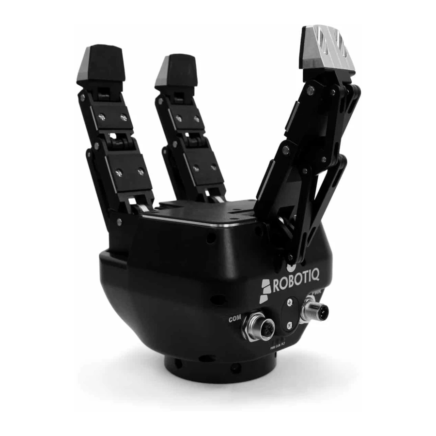
Gripper. The Adaptive Gripper has three articulated fingers, i.e. Finger A in front of Finger B and Finger C, that each have three joints (three phalanxes per finger), as shown in Figure 1.1. The Gripper can engage up to ten points of contact with an object (three on each of the phalanges plus the palm). - Page 5 Instruction Manual Two different types of movements can be performed with the Gripper. The first determines the type of grip being used and simultaneously changes the orientation of Fingers B and C as shown in Figure 1.2. This movement is referred to as the 'Operation Mode'.
- Page 6 Figure 1.3 : The four Operation Modes of the 3-Finger Adaptive Robot Gripper. The second movement of the Gripper is the closing and opening of the fingers as shown in Figure 1.4. This action is performed with a single input from the user. Each finger is not controlled independently; the Gripper itself closes each finger until it reaches a stable configuration, on an object or against the Gripper palm.
- Page 7 Robotiq 3-Finger Adaptive Robot Gripper Instruction Manual Two types of grips occur when closing the 3-Finger Adaptive Robot Gripper on an object: Fingertip Grip or Encompassing Grip. Fingertip Grip is when an object is only held by the distal phalanxes. This type of grip is similar to what is done with conventional industrial parallel grippers.
- Page 8 Robotiq 3-Finger Adaptive Robot Gripper Instruction Manual Info Operation Modes are inputs to the Gripper. Whether the fingers close to produce an Encompassing or Fingertip grip is decided at the Gripper level automatically . It will depend The Operation Mode;...
- Page 9 Robotiq 3-Finger Adaptive Robot Gripper Instruction Manual Figure 1.6 : Operation Modes vs. Types of Grip. Robotiq inc. © 2008 - 2014...
-
Page 10: Safety
Programming Decommissioning This documentation explains the various components of the 3-Finger Gripper and its general operation. Please read this documentation thoroughly and be sure to understand its contents before handling the 3-Finger Gripper. The drawings and photos in this documentation are representative examples and differences may exist between them and the delivered product. -
Page 11: Warning
Do not install or operate a Gripper that is damaged or lacking parts. Never supply the Gripper with an alternative current source. Make sure all cord sets are always secured at both ends, at the Gripper and at the robot. Always respect the recommended keying for electrical connections. -
Page 12: Intended Use
Robotiq 3-Finger Adaptive Robot Gripper Instruction Manual 2.2 Intended use The Gripper unit is designed for gripping and the temporary secure holding of parts. Caution The Gripper is NOT intended for applying force against objects or surfaces. The product is intended for installation on a robot or other automated machinery and equipment. -
Page 13: Installation
3-Finger Gripper prior to installation. Warning Do not operate the Gripper, or even turn on the power supply, before it is firmly anchored. The Gripper fingers may move and cause injury or damage. 3.1 Scope of delivery... -
Page 14: Environmental And Operating Conditions
Robotiq 3-Finger Adaptive Robot Gripper Instruction Manual 3.2 Environmental and operating conditions The Gripper is designed for industrial applications. Always respect the conditions specified for storage and operating environments: SPECIFICATION VALUE Minimum storage/transit temperature -22°F [-30°C] Maximum storage/transit temperature 140°F [60°C] Minimum operating temperature 14°F [-10°C]... -
Page 15: Mechanical Connections
3.3 Mechanical connections You must use a coupling to attach the Gripper to the robot. Be sure to use the coupling related to your robot model. If there is no coupling for your robot, you can modify a blank coupling model or Robotiq can create a custom version based on blanks in section 6.6... -
Page 16: Power Supply Specifications
3.4 Power supply specifications The Gripper needs to be supplied by a DC voltage source. This power supply is not included with the Gripper. The following table shows the specifications regarding the power supply required to operate the Gripper properly. -
Page 17: Wiring
Two connections are needed for the 3-Finger Gripper , one for power and one for communication. On the Gripper, both are located on the Connection Panel shown in Figure 3.5.1. Figure 3.5.1 : Power, USB and communication receptacles shown with USB cover removed. - Page 18 Use proper cabling management. Be sure to have enough forgiveness in the cabling to allow movement of the Gripper along all axes without putting tension on the cable or pulling out the connectors. Always protect the controller-side connector of the cable with a strain relief cable clamp.
-
Page 19: Power Connection
Figure 3.5.1.1 : Power connection diagram of the 3-Finger Adaptive Robot Gripper. Caution The 4A fuse is external to the Gripper. It is not provided by Robotiq and the user is responsible for proper installation. The pin-out of the power connectors is detailed in Figure 3.5.1.2. - Page 20 Robotiq 3-Finger Adaptive Robot Gripper Instruction Manual Figure 3.5.1.2 : Gripper Power Input and Power Connector. Info RS485 communication is standard on all 3-Finger Grippers, see the Serial Communication Protocol section. If not using RS485 communication, simply leave the two wires unconnected.
-
Page 21: Communication Connection
The following table summarizes the communication protocols available for the Gripper. Note that only one protocol option is available in a given Gripper unit. The Gripper that you have was configured before shipment with only one of the following protocols. -
Page 22: Devicenet Communication Protocol
DeviceNet standard requires a 120 Ohms resistor to be mounted at the beginning and at the end of the line. If the Gripper is the end of line, then a 120 Ohms resistor must be mounted between pin 4 and 5. - Page 23 Robotiq 3-Finger Adaptive Robot Gripper Instruction Manual Figure 3.5.2.2 : Power connection diagram for the 3-Finger Gripper using DeviceNet Fieldbus. Factory settings for DeviceNet protocol : Identification Settings Info Decimal Value ( base 10 ) Hexadecimal Value ( base 16 )
- Page 24 Robotiq 3-Finger Adaptive Robot Gripper Instruction Manual BUS SETTINGS MAC ID : Baud Rate : 250 KBaud DATA SETTINGS Prod. Data Length : Cons. Data Length : Robotiq inc. © 2008 - 2014...
-
Page 25: Canopen Communication Protocol
CANopen standard requires a 120 Ohms resistor to be mounted at the beginning and at the end of the line. If Gripper is the end of line, then a 120 Ohms resistor must but mounted between pin 4 and 5. - Page 26 Robotiq 3-Finger Adaptive Robot Gripper Instruction Manual Figure 3.5.2.4 : Power connection diagram of the 3-Finger Gripper using CANopen Fieldbus. Factory settings for CANopen protocol: IDENTIFICATION SETTINGS Info Decimal value (base 10) Hexadecimal value (base 16) Vendor ID : 0x00000044...
- Page 27 Robotiq 3-Finger Adaptive Robot Gripper Instruction Manual BUS SETTINGS MAC ID : Baud Rate : 1 MBaud DATA SETTINGS Index Size Send Object 0x2000 Receive Object 0x2200 Output Databytes Input Databytes Hint The CANopen communication interface supports SDO (Service Data Object) and PDO (Process Data Object) protocols.
-
Page 28: Real-Time Ethernet Communication Protocol
3-Finger Adaptive Robot Gripper and the cable (male) provided with your Gripper. Figure 3.5.2.5 : Real-time Ethernet communication pin-out. The 3-Finger Adaptive Robot Gripper features an auto-crossover, so there is no need to cross the RX/TX signals. Factory settings for each Ethernet protocols:... - Page 29 Robotiq 3-Finger Adaptive Robot Gripper Instruction Manual IDENTIFICATION SETTINGS EtherCAT EtherNet/IP PROFINET Modbus TCP/IP Vendor ID : 0x0000FFFF Vendor ID : 0x0000011B Vendor ID : 0x0000011E N / A Product Code 0x0000000B Product Code 0x0000010D Device ID : 0x0000010A Serial...
- Page 30 Robotiq 3-Finger Adaptive Robot Gripper Instruction Manual BUS SETTINGS EtherCAT EtherNet/IP PROFINET Modbus TCP/IP N / A (see IP Address : 192.168.1.11 Bus Startup Automatic IP Address : 192.168.1.11 info note) Netmask : 255.255.255. Watchdog 1000ms Netmask : 255.255.255. Time...
- Page 31 Robotiq 3-Finger Adaptive Robot Gripper Instruction Manual DATA SETTINGS EtherCAT EtherNet/IP PROFINET Modbus TCP/IP Input Data Prod. Data Output Data Bytes (16) N / A Bytes : Length : Output Data Cons. Data Module N / A Bytes : Length :...
-
Page 32: Serial Communication Protocol
RS485 serial communication is standard on all 3-Finger Adaptive Robot Grippers, this communication is available through the power connector. Figure 3.5.2.6 shows the pin-out of the communication connectors when used in serial mode for the receptacle (male) present on the 3-Finger Adaptive Robot Gripper and the cable (female) provided with your Gripper. - Page 33 Robotiq 3-Finger Adaptive Robot Gripper Instruction Manual Figure 3.5.2.7 : Serial communication converted from RS485 to RS232. Factory settings for Modbus RTU protocols : IDENTIFICATION SETTINGS Slave ID : Robotiq inc. © 2008 - 2014...
- Page 34 Preset Single Register (FC06) Preset Multiple Registers (FC16) Exception Responses Not supported Slave ID 0x0009 (9) Robot Output / Gripper Input First Register 0x03E8 (1000) Robot Input / Gripper Output First Register 0x07D0 (2000) section 4.7.1 for details DATA SETTINGS...
-
Page 35: Control
Since the Robotiq 3-Finger Gripper has its own internal controller, high-level commands such as "Go to requested position" are used to control it. The embedded Robotiq controller takes care of the regulation of the speed and the force prescribed, while the mechanical design of the fingers automatically adapts to the shape of object(s). - Page 36 Figure 4.1.1 : 3-Finger Gripper connections. The Gripper controller has an internal memory that is shared with the robot controller. One part of the memory is for the robot output, gripper functionalities. The other part of the memory is for the robot input, gripper status. Two...
- Page 37 Mode is currently active or if the Gripper is closed or open. Object Status - There is also an Object Status that let you know if there is an object in the Gripper and, in the affirmative, how many fingers are in contact with it.
-
Page 38: Status Leds
Robotiq 3-Finger Adaptive Robot Gripper Instruction Manual 4.2 Status LEDs Three status LED lights provide general information about the 3-Finger Adaptive Robot Gripper status. Figure 4.2.1 shows the LEDs and their locations. Figure 4.2.1 : Status LEDs. Robotiq inc. © 2008 - 2014... -
Page 39: Supply Led
COLOR STATE INFORMATION No fault detected A minor fault occurred (or the Gripper is booting) Blinking A major fault occurred Info A major fault refers to a situation where the Gripper must be reactivated. Robotiq inc. © 2008 - 2014... -
Page 40: Gripper Register Mapping
4.3 Gripper register mapping The 3-Finger Gripper firmware provides functionalities such as the direct position control of the fingers via "Go To" commands. There are also additional advanced options, such as the individual control of the fingers or the Scissor Mode. - Page 41 Robotiq 3-Finger Adaptive Robot Gripper Instruction Manual Register mapping for the Simplified Control Mode : Caution Byte numeration starts on zero and not at 1 for the functionalities and status registers. REGISTER ROBOT OUTPUT / ROBOT INPUT / STATUS FUNCTIONALITIES...
- Page 42 Robotiq 3-Finger Adaptive Robot Gripper Instruction Manual Register mapping for the Advanced Control Mode : REGISTER ROBOT OUTPUT / ROBOT INPUT / STATUS FUNCTIONALITIES Byte 0 ACTION REQUEST GRIPPER STATUS Byte 1 GRIPPER OPTIONS OBJECT DETECTION Byte 2 GRIPPER OPTIONS #2 (EMPTY)
-
Page 43: Robot Output Registers & Functionalities
0x1 – Go to Pinch Mode. 0x2 – Go to Wide Mode. 0x3 – Go to Scissor Mode. rGTO: The "Go To" action moves the Gripper fingers to the requested position using the configuration defined by the other registers and the rMOD bits. - Page 44 Address: Byte 1 rICF: In Individual Control of Fingers Mode each finger receives its own command (position request, speed and force) unless the Gripper is in the Scissor Grasping Mode and the Independent Control of Scissor ( rICS ) is not activated.
- Page 45 Symbols rPRA This register is used to set the target position of the fingers for the Adaptive Gripper (or Finger A only if bit rICF set). The positions 0x00 and 0xFF correspond respectively to the fully opened and fully closed mechanical stops.
- Page 46 Address: Byte 4 Bits rSPA Symbols This register is used to set the Gripper closing or opening speed (or Finger A only if bit rICF is set) in real time, however, setting a speed will not initiate a motion. rSPA...
- Page 47 Bits Symbols rFRA The force setting defines the final grasping force of the Adaptive Gripper (or Finger A only if bit rICF is set). The force will fix maximum current sent to the motors while in motion. For each finger, if the current limit is exceeded, the finger stops and triggers an object detection notification.
- Page 48 Robotiq 3-Finger Adaptive Robot Gripper Instruction Manual Bits rPRC Symbols This register is used to set the Finger C target position. It is only applied if the Individual Control of Finger option is selected (bit rICF is set). Please refer to rPRA (position request) register for more information.
- Page 49 Robotiq 3-Finger Adaptive Robot Gripper Instruction Manual This register is used to set the scissor axis force. It is only applied if the Individual Control of Scissor option is selected (bit rICS is set). Please refer to rFRA (force) register for more information.
-
Page 50: Robot Input Registers & Status
0x1 - Go to Position Request. gIMC : Gripper status, returns the current status of the Gripper. 0x00 - Gripper is in reset (or automatic release) state. See Fault status if Gripper is activated. 0x01 - Activation is in progress. - Page 51 Resetting the contact detection repeatedly at high frequency using the rGTO bit may cause a major failure of the Gripper. This is not considered normal usage of the Gripper and it is not recommended by Robotiq. Robotiq inc. © 2008 - 2014...
- Page 52 For example, picking up a thin object in a Fingertip Grip may be successful without object detection occurring. For this reason, use this feature with caution. In these applications the "Gripper is stopped" status of register gSTA is sufficient to proceed to the next step of the routine.
- Page 53 0x0F - Automatic release completed. Reset and activation is required. Caution All major faults will require you to reset the Gripper (rACT bit == 0 then rACT bit == 1) which will initiate motion from the Gripper for the re-calibration procedure before recovering normal control of the Gripper.
- Page 54 : Echo of the requested position of the Gripper (rPRA), 0x00 is the minimum position (fully open) and 0xFF is the maximum position (fully closed). If commanding the Gripper in individual control mode, gPRA is the echo of Finger A, otherwise it is the general position requested to all fingers.
- Page 55 Address: Byte 7 Bits Symbol gPOB gPOB : Returns the actual position of the Gripper Finger B, 0x00 is the minimum position (fully open) and 0xFF is the maximum position (fully closed). Register: FINGER B CURRENT Address: Byte 8 Bits...
- Page 56 Register: SCISSOR POSITION Address: Byte 13 Bits Symbol gPOS gPOS : Returns the actual position of the Gripper scissor action, 0x00 is the minimum position (fully open) and 0xFF is the maximum position (fully closed). Register: SCISSOR CURRENT Address: Byte 14 Bits...
-
Page 57: Control Logic - Example
Instruction Manual 4.6 Control logic - example Figure 4.6.1 represents the general structure and logic for control of the 3-Finger Adaptive Robot Gripper. See the following subsections for details on specific industrial communication protocol examples. Figure 4.6.1 : Example of 3-Finger Adaptive Robot Gripper control logic. -
Page 58: Modbus Rtu Communication Protocol
Note The Adaptive Gripper register values are updated at a 100Hz frequency. It is therefore recommended to send commands with a minimum interval delay of 10ms. Note that the updated frequency may drop under some conditions where the response time would be longer. -
Page 59: Connection Setup
(bytes – 8 bits) from the Robotiq 3-Finger Gripper . The first Gripper output Modbus register (0x07D0) is composed from the first Robotiq 3-Finger Adaptive Robot Gripper registers (byte 0 and byte 1). Robotiq inc. © 2008 - 2014... -
Page 60: Read Holding Registers (Fc03)
Instruction Manual 4.7.2 Read holding registers (FC03) Function code 03 (FC03) is used for reading the status of the Gripper (robot input). Examples of such data are Gripper Status, Object Status, Finger Position, etc. Ex: This message asks for register 0x07D0 (2000) and register 0x07D1 (2001) which contains Gripper Status, Object Detection, Fault Status and Position Request Echo. -
Page 61: Preset Single Register (Fc06)
Instruction Manual 4.7.3 Preset single register (FC06) Function code 06 (FC06) is used to activate functionalities of the Gripper (robot output). Examples of such data are Action Request, Velocity, Force, etc. Ex: This message requests the initialization of the Gripper by setting register 0x03E8 (1000), which contains an Action Request and Gripper Options, to 0x0100. -
Page 62: Preset Multiple Registers (Fc16)
Instruction Manual 4.7.4 Preset multiple registers (FC16) Function code 06 (FC16) is used to activate functionalities of the Gripper (robot output). Examples of such data are Action Request, Speed, Force, etc. Ex: This message requests to set Position Request, Speed and Force of the Gripper by setting register 0x03E9 (1001) and 0x03EA. -
Page 63: Master Read&Write Multiple Registers (Fc23)
4.7.5 Master read&write multiple registers (FC23) Function code 23 (FC23) is used for reading the status of the Gripper (robot input) and activating functionalities of the Gripper (robot output) simultaneously. Examples of such data are Gripper Status, Object Status, Finger Position, etc. - Page 64 4727 Cyclic Redundancy Check (CRC) Note The 3 Finger Adaptive Gripper register values are updated at a 200Hz frequency. It is therefore recommended to send FC23 commands with a minimum interval delay of 5ms. Robotiq inc. © 2008 - 2014...
-
Page 65: Modbus Rtu Example
Modbus RTU protocol. The example is typical of a pick and place application. After activating the Gripper, the robot is moved to a pick-up location to grip an object. It moves again to a second location to release the gripped object. - Page 66 03E8 Address of the first register 0003 Number of written registers 0130 Cyclic Redundancy Check (CRC) Step 2: Read Gripper status until the activation is completed Request is: 09 03 07 D0 00 01 85 CF where BITS DESCRIPTION SlaveID...
- Page 67 Activation", gIMC = 3 for "Activation and mode change are completed" 4C15 Cyclic Redundancy Check (CRC) Step 3: Move the robot to the pick-up location Step 4: Close the Gripper at full speed and full force Robotiq inc. © 2008 - 2014...
- Page 68 = 6 bytes) 0900 Value written to register 0x03E9 (ACTION REQUEST = 0x09 and GRIPPER OPTIONS = 0x00): rACT = 1 for "Activate Gripper" rMOD=0 for "Go to Basic Mode" , rGTO = 1 for "Go to Requested Position"...
- Page 69 Robotiq 3-Finger Adaptive Robot Gripper Instruction Manual Step 5: Read Gripper status until the grip is completed Request is: 09 03 07 D0 00 08 45 C9 where BITS DESCRIPTION SlaveID Function Code 03 (Read Holding Registers) 07D0 Address of the first requested register...
- Page 70 Number of data bytes to follow (8 registers x 2 bytes/register = 16 bytes) B9EA Content of register 0x07D0 (GRIPPER STATUS = 0xB9, OBJECT STATUS = 0xEA): gSTA = 2 for "Gripper is stopped. All fingers stopped before requested position" gDTA = gDTB = gDTC = 2 for "Finger X has stopped due to a contact while...
- Page 71 Cyclic Redundancy Check (CRC) Step 6: Move the robot to the release location Step 7: Open the Gripper at full speed and full force Request is: 09 10 03 E8 00 03 06 09 00 00 00 FF FF 72 19...
- Page 72 03E8 Address of the first register 0003 Number of written registers 0130 Cyclic Redundancy Check (CRC) Step 8: Read gripper status until the opening is completed Request is: 09 03 07 D0 00 08 45 C9 where BITS DESCRIPTION SlaveID...
- Page 73 Instruction Manual Number of data bytes to follow (8 registers x 2 bytes/register = 16 bytes) 39C0 Content of register 0x07D0 (GRIPPER STATUS = 0x39, OBJECT STATUS = 0xC0): gSTA = 0 for "Gripper is in motion towards requested position" 0000...
- Page 74 Robotiq 3-Finger Adaptive Robot Gripper Instruction Manual F9FF Content of register 0x07D0 (GRIPPER STATUS = 0xF9, OBJECT STATUS = 0xFF): gSTA = 3 for "Gripper is stopped. All fingers reached requested position" 0000 Content of register 0x07D1 (FAULT STATUS = 0x00,...
-
Page 75: Modbus Tcp Communication Protocol
Note The Adaptive Gripper register values are updated at a 100Hz frequency. It is therefore recommended to send commands with a minimum interval delay of 10ms. Note that the updated frequency may drop under some conditions where the response time would be longer. -
Page 76: Read Input Registers (Fc04)
Instruction Manual 4.8.2 Read Input Registers (FC04) Function code 04 (FC04) is used for reading the status of the Gripper (robot input). Examples of such data are Gripper Status, Object Status, Finger Position, etc. Ex: This message asks for registers 0x0000 (0000) to 0x0006 (0006) which contain all the robot input statuses except for the scissor axis. -
Page 77: Preset Multiple Registers (Fc16)
Instruction Manual 4.8.3 Preset Multiple Registers (FC16) Function code 06 (FC16) is used to activate functionalities of the Gripper (robot output). Examples of such data are Action Request, Position Request, Speed, Force, etc. Ex: This message requests to set several options for the Gripper by setting registers from 0x0000 (0000) to 0x0003. -
Page 78: Modbus Tcp Example
Modbus TCP protocol. The example is typical of a pick and place application. After activating the Gripper, the robot is moved to a pick-up location to grip an object. It moves again to a second location to release the gripped object. - Page 79 Function Code 16 (Preset Multiple Registers) 03E8 Address of the first register 0003 Number of written registers Step 2: Read Gripper status until the activation is completed Request is: 45 33 00 00 00 06 02 03 07 D0 00 01 where BITS...
- Page 80 0x31, OBJECT STATUS = 0x00): gACT = 1 for "Gripper Activation", gIMC = 3 for "Activation and mode change are completed" Step 3: Move the robot to the pick-up location Step 4: Close the Gripper at full speed and full force Robotiq inc. © 2008 - 2014...
- Page 81 = 6 bytes) 0900 Value written to register 0x03E9 (ACTION REQUEST = 0x09 and GRIPPER OPTIONS = 0x00): rACT = 1 for "Activate Gripper" rMOD=0 for "Go to Basic Mode" , rGTO = 1 for "Go to Requested Position"...
- Page 82 Robotiq 3-Finger Adaptive Robot Gripper Instruction Manual Step 5: Read Gripper status until the grip is completed Request is: 77 6B 00 00 00 06 02 04 07 D0 00 08 where BITS DESCRIPTION 776B Unique transaction identifier (chosen randomly)
- Page 83 Function Code 04 (Read Input Registers) Number of data bytes to follow (8 registers x 2 bytes/register = 16 bytes) 39C0 Content of register 0x07D0 (GRIPPER STATUS = 0x39, OBJECT STATUS = 0xC0): gSTA = 0 for "Gripper is in motion towards requested position" 00FF...
- Page 84 REQUEST ECHO = 0x00, SCISSOR POSITION = 0x89) 0000 Content of register 0x07D7 (SCISSOR CURRENT = 0x00) Step 6: Move the robot to the release location Step 7: Open the Gripper at full speed and full force Robotiq inc. © 2008 - 2014...
- Page 85 = 6 bytes) 0900 Value written to register 0x03E9 (ACTION REQUEST = 0x09 and GRIPPER OPTIONS = 0x00): rACT = 1 for "Activate Gripper" rMOD=0 for "Go to Basic Mode" , rGTO = 1 for "Go to Requested Position"...
- Page 86 Function Code 16 (Preset Multiple Registers) 03E8 Address of the first register 0003 Number of written registers Step 8: Read Gripper status until the opening is completed Request is: D6 05 00 00 00 06 02 04 07 D0 00 08 where BITS...
- Page 87 Function Code 04 (Read Input Registers) Number of data bytes to follow (8 registers x 2 bytes/register = 16 bytes) 39C0 Content of register 0x07D0 (GRIPPER STATUS = 0x39, OBJECT STATUS = 0xC0): gSTA = 0 for "Gripper is in motion towards requested position" 0000...
-
Page 88: Application With Universal Robots
0x00) Step 9: Loop back to step 3 if other objects have to be gripped. 4.8.5 Application with Universal Robots This section contains some additional information relative to the communication between the Gripper and the Univer sal Robots model UR-5... - Page 89 Instruction Manual Modbus TCP works with 16-bit registers, whereas the Adaptive Gripper is configured using 8-bit bytes. Therefore, you must compute the value for each 16-bit register using two bytes. Also, the endianness is different for the Gripper than for the robots.
-
Page 90: User Interface
Robotiq 3-Finger Adaptive Robot Gripper Instruction Manual 5. User Interface Visit http://support.robotiq.com to get the latest installer of the Robotiq User Interface along with appropriate documentation. See the Robotiq User Interface Instruction Manual for details on usage of the RUI. -
Page 91: Specifications
Robotiq 3-Finger Adaptive Robot Gripper Instruction Manual 6. Specifications 6.1 Technical dimensions Figure 6.1.1 : Robotiq 3-Finger Adaptive Robot Gripper technical dimensions. Robotiq inc. © 2008 - 2014... -
Page 92: Mechanical Specifications
Robotiq 3-Finger Adaptive Robot Gripper Instruction Manual 6.2 Mechanical specifications Specification Imperial units Metric units Gripper Opening (see Pad design 0-6.1 in [0-155 mm] and customization section Gripper Approximate Weight 5 lbs [2.3 kg] Recommended Payload 22 lbs [10 kg]... - Page 93 Where, F is the force that is applied to the load by the Gripper. Note that at the fingertips, the maximum force that can be applied is when Fingers B and C force against Finger A. In this case, the force can be up to twice the Maximum Actuation Force, so 40N.
-
Page 94: Design And Customization
6.3.1 Finger pad replacement and customization The Robotiq 3-Finger Adaptive Robot Gripper Finger Pads are a usable part meant for frequent change (after a maximum of 1 Mio. cycles) that can be customized. The Finger Pad S-013 and Finger Pad S-014 are fixed to the Gripper Finger as shown in figure 6.3.1.1. - Page 95 Custom pads must be fixed with both available thread patterns, never modify the Fingers without Robotiq's consent first. Figure 6.3.1.2 : Bolt pattern of the Proximal and Median Pads of the 3-Finger Adaptive Robot Gripper Robotiq inc. © 2008 - 2014...
-
Page 96: Palm Pad Replacement And Customization
The Robotiq 3-Finger Adaptive Robot Gripper Palm Pad is a usable part meant for frequent change (maximum 1 Mio. cycles) that can be customized. The Palm Pad S-071 is fixed to the Gripper as shown in figure 6.3.2.1. For a list of available parts see section 8. - Page 97 Robotiq 3-Finger Adaptive Robot Gripper Instruction Manual Figure 6.3.2.2 : Bolt pattern of the Palm Pad for the 3-Finger Adaptive Robot Gripper. Robotiq inc. © 2008 - 2014...
-
Page 98: Fingertip Replacement And Customization
The Robotiq 3-Finger Adaptive Robot Gripper Fingertip is a usable part meant for frequent change (maximum 1 Mio. cycles) that can be customized. The Fingertip S-016 is fixed to the Gripper Finger as shown in figure 6.3.3.1. For a list of available parts see section 8. - Page 99 Robotiq 3-Finger Adaptive Robot Gripper Instruction Manual Figure 6.3.3.2 : Bolt pattern of the Fingertip for the 3-Finger Adaptive Robot Gripper Fingers. Robotiq inc. © 2008 - 2014...
-
Page 100: Moment Of Inertia And Center Of Mass
Gripper. Here is the approximate moment of inertia matrix for the 3-Finger Adaptive Gripper : Here is the approximate position of the center of mass for the 3-Finger Adaptive Gripper : Robotiq inc. © 2008 - 2014... -
Page 101: Electrical Ratings
Robotiq 3-Finger Adaptive Robot Gripper Instruction Manual 6.5 Electrical ratings SPECIFICATION VALUE Operating Supply Voltage 24 V Absolute Maximum Supply Voltage 28 V Quiescent Power (minimum power consumption) 4.1 W Peak Power (at maximum gripping force) 36 W Maximum RMS Supply Current (supply voltage at 24V) 1.5 A... -
Page 102: Couplings
6.6 Couplings 6.6.1 Blank coupling The 3-Finger Adaptive Robot Gripper blank coupling can be used to create a custom coupling between the Gripper Universal Wrist and your robot. Provided screw clearance and dowel pin hole are meant for installation on the Universal Wrist. -
Page 103: Yaskawa Sda-5D_10D Coupling
Instruction Manual 6.6.2 Yaskawa SDA-5D_10D coupling The 3-Finger Adaptive Robot Gripper Yaskawa coupling is meant for coupling between the Gripper Universal Wrist and Yaskawa SDA-5D or Yaskawa SDA-10D robots. Provided screw clearance and dowel pin hole are meant for installation on the Universal Wrist. Top face shown in figure 6.6.2.1 is meant to be on the wrist side while bottom face is meant to be on the robot side. -
Page 104: Dimensions For Custom Coupling
Figure 6.6.3.1 : 3-Finger Adaptive Robot Gripper dimensions for custom coupling. Info The Gripper must be secured with all six (6) of the # 6-32 UNC screws. Use the 3/16 Dowel pin for indexing, pin must be press fit in the custom coupling, it is slip fit on the Gripper Universal Wrist side. -
Page 105: Maintenance
The Adaptive Gripper requires only external maintenance with limited downtime. Maintenance of the 3-Finger Adaptive Robot Gripper is required after specified usage, measured in time (normal 40h week) or in cycles (requesting an open and close movement from the Gripper). Following the maintenance interval will ensure : Correct functioning of your Gripper. - Page 106 Robotiq 3-Finger Adaptive Robot Gripper Instruction Manual Maintenance operations are for average normal usage of the Gripper, the maintenance intervals must be adjusted according to environmental conditions such as: Operating temperature Humidity Presence of chemical(s) Presence of physical parts (debris, scraps, dust, grease etc.)
-
Page 107: Gripper Cleaning
Rotate the screwdriver counter clockwise to open the finger. Clean the Gripper with a dry towel, remove all debris, dirt and dust from the surface of the Gripper. Visually inspect the Gripper and pay attention to any visible wear or damage. -
Page 108: Applying Grease
When the finger is closed the finger base cogs are visible, clean excess grease with a dry tissue or towel, then apply grease between the gear cogs (use the Mobilith SHC grease syringe provided by Robotiq). Completely open the finger and then completely close the finger, this will allow the grease to spread. -
Page 109: Periodic Inspection
7.4 Finger Pad Replacement Check for any collision damage, if damage is visible, contact Robotiq Support. Check for any sign of wear on the Gripper chassis, if wear is present and may affect Gripper performance, contact Robotiq Support. Put the Gripper back in place, make sure to maintain the initial orientation of your Gripper. -
Page 110: Finger Pad Replacement
Spare Parts, Kits and Accessories section to order Robotiq 3-Finger Adaptive Robot Gripper replacement parts. Note Always turn off robot and Gripper power supply before performing maintenance operations on the Gripper. Procedure Remove the Gripper from the robot following schematics in section 3.3 Mechanical connections... -
Page 111: Gripper Palm Replacement
Spare Parts, Kits and Accessories section to order Robotiq 3-Finger Adaptive Robot Gripper replacement parts. Note Always turn off robot and Gripper power supply before performing maintenance operations on the Gripper. Procedure Remove the Gripper from the robot following schematics in section 3.3 Mechanical connections... -
Page 112: Fingertip Replacement
Spare Parts, Kits and Accessories section to order Robotiq 3-Finger Adaptive Robot Gripper replacement parts. Note Always turn off robot and Gripper power supply before performing maintenance operations on the Gripper. Procedure Remove the Gripper from the robot following schematics in section 3.3 Mechanical connections... -
Page 113: Gear Replacement
Spare Parts, Kits and Accessories section to order Robotiq 3-Finger Adaptive Robot Gripper replacement parts. Note Always turn off robot and Gripper power supply before performing maintenance operations on the Gripper. Warning Always wear protective glasses when doing maintenance work on the 3-Finger Adaptive Robot Gripper, especially when manipulating snap rings. -
Page 114: Overhaul
2 M cycles, 1 year or at warranty None None expiration Gripper overhaul is necessary when the Gripper reaches 2 M cycles or at warranty expiration. Overhaul is done by Robotiq, please contact Robotiq Support Service. Robotiq inc. © 2008 - 2014... -
Page 115: Spare Parts, Kits And Accessories
Robotiq 3-Finger Adaptive Robot Gripper Instruction Manual 8. Spare Parts, Kits and Accessories Spare parts, kits and accessories list : The following list is up to date at print time and is subject to change, check online for updates. Item... - Page 116 Robotiq 3-Finger Adaptive Robot Gripper Instruction Manual S-152 AGS-APL-152 Adapter plate for 56 mm PCD , eight (8) M5 screws, one (1) 4 mm M6 dowel pin. Meant for use on S-101 Coupling. S-153 AGS-APL-153 Adapter plate for 40 mm PCD , five (5) M6 screws, one (1) 6 mm M6 dowel pin.
- Page 117 Robotiq 3-Finger Adaptive Robot Gripper Instruction Manual S-165 Adapter plate for three (3) M3 AGS-APL-165 screws on 33 mm PCD , two (2) 3 mm M6 dowel pin. S-166 Adapter plate for six (6) M5 screws AGS-APL-166 on 39 mm PCD , two (2) 4 mm slip fit dowel holes.
- Page 118 Robotiq 3-Finger Adaptive Robot Gripper Instruction Manual Finger Pads includes : AGS-PAD-S013/14 one (1) Proximal Pad S-013, 606 1 aluminium body with black silicone cover. one (1) Median Pad S-014, 6061 aluminium body with black silicone cover. four (4) 4-40 X 1/4 Flat Head...
- Page 119 Instruction Manual Grease syringe includes : ACC-LUB-SHC1500 1g high viscosity grease syringe for worm gears of the 3-Finger Adaptive Gripper Pitch Circle Diameter One 3-Finger Gripper requires two (2) rotating fingertips to work properly. Robotiq inc. © 2008 - 2014...
-
Page 120: Troubleshooting
After reprogramming communication options, wait until the red LED stops blinking to update the configuration. Other problems If the system shuts down (blue LED goes off) when the Gripper activates, check the power supply, the power supply must meet the following requirements When attempting to move the Gripper, make sure ''go to requested position'' (rGTO) is active (set to 1), in the User Interface, the Go to Requested Position case must stay checked for the Gripper to move. - Page 121 Use the same protocol options (fixed IP, auto-neg, full duplex, etc.) as shown in the Communication protocol panel. Set your Ethernet network card to use fixed addresses other than the Gripper address. Set your master Ethernet network card to use fixed addresses other than the Gripper address (for example use 192.168.1.10 if Gripper address is 192.168.1.11).
- Page 122 Instruction Manual Finger movement is erratic or not fluid. A: Finger movement can be altered by debris, clean the Gripper and make sure no debris or fluid is present between the finger phalanx and bar (repeat for each finger). return to top Q: Gripping force changed since first usage.
-
Page 123: Warranty
Robotiq shall not be liable for damages resulting from the use of the product, nor shall be responsible for any failure in the performance of other items to which the product is connected or the operation of any system of which the product may be a part. -
Page 124: Contact
Robotiq 3-Finger Adaptive Robot Gripper Instruction Manual 11. Contact www.robotiq.com Go to Contact Us Phone 1-888-ROBOTIQ (762-6847) 1-418-800-0045 (outside US and Canada) 1-418-800-0046 Technical support and Engineering extension 207 Sales US extension 122 Head office Robotiq: 966, chemin Olivier Suite 325... -
Page 125: Ec Declaration Of Conformity
Robotiq 3-Finger Adaptive Robot Gripper Instruction Manual EC Declaration of conformity Robotiq inc. © 2008 - 2014...
Need help?
Do you have a question about the Gripper and is the answer not in the manual?
Questions and answers