
Subscribe to Our Youtube Channel
Related Manuals for Vivotek MA9322-EHTV


Summary of Contents for Vivotek MA9322-EHTV
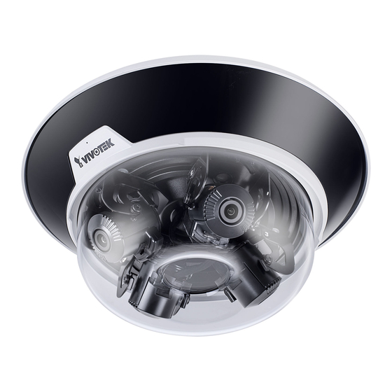
- Page 1 MA9322-EHTV Panoramic Multi-sensor Network Camera User ’s Manual 20MP • 360° Surround View • IP66 • IK10 • Remote Focus • SNV Smart Stream III • PoE • -40°C ~ 60°C Wide Operating Temperature Rev. 1.0...
-
Page 2: Table Of Contents
Applications > DI and DO ..........................142 Applications > Tampering detection ........................143 Applications > Audio detection ......................... 144 Applications > Package management - a.k.a., VADP (VIVOTEK Application Development Platform) ..... 146 Recording > Recording settings ........................149 Storage > Storage management ........................154... -
Page 3: Overview
90%* while still maintaining excellent image quality compared to traditional H.264 without smart streaming. In addition to its versatile coverage, the MA9322-EHTV is armed with a robust IP66 and IK10-rated housing to enable the multidirectional camera to withstand rain and dust as well as to protect against vandalism or tampering. -
Page 4: Read Before Use
Network Camera and ensure proper operations. For creative and professional developers, the URL Commands of the Network Camera section serves as a helpful reference to customizing existing homepages or integrating with the current web server. Package Contents ■ MA9322-EHTV ■ Quick Installation Guide ■ Screws / desiccant bag ■ T10 torx wrench ■... -
Page 5: Symbols And Statements In This Document
VIVOTEK Symbols and Statements in this Document INFORMATION: provides important messages or advices that might help prevent inconvenient or problem situations. NOTE: Notices provide guidance or advices that are related to the functional integrity of the machine. Tips: Tips are useful information that helps enhance or facilitae an installation, function, or process. - Page 6 VIVOTEK Top View Through holes for ceiling-mount or AM-21C Threaded holes for AM-529 Top mounting plate Inner View Slide track Lens (sensor) module, 3-axis adjustable RJ45 Ethernet port Reset button Cable gland for Ethernet Cable gland for I/O combo Microphone...
- Page 7 VIVOTEK IR LED contacts MicroSD card slot For the installation using optional accessories, refer to the Optional Accessories Installation Guide User's Manual - 7...
- Page 8 VIVOTEK Power Consumption 802.3at 100~240V LAN/PoE GE LAN GE LAN 24V 3.5A injector Due to its onboard heater for operation in the low temperature environments, care should be taken when selecting the power source for the camera. Listed below are the...
-
Page 9: Mounting Options
VIVOTEK Mounting Options With its remote focus lenses, the lens modules can be aiming at different areas at different distances. Below are some sample scenarios with lenses' shooting directions adapted to them. The Zoom function is found in Configuration > Media > Image > Focus window. - Page 10 VIVOTEK When installed at a corner, one of its lens can be turned facing downward to cover the area directly underneath the camera. 10 - User's Manual...
-
Page 11: Ceiling Mount
VIVOTEK Ceiling Mount For other mounting options, please refer to the Installation Guide for Optional Accessories. The camera can be directly installed to a wall or ceiling. Refer to the following discussion for more on pendant mount, pole mount, and corner mount options. - Page 12 VIVOTEK 3. Remove the camera from the top mounting plate by pressing the release button. Turn the camera counter-clockwise, and then lift it off the mounting plate. Main body Base plate 4. Remove the waterproof connectors. If you do not need to route I/O wires, leave the plastic cap in place.
- Page 13 VIVOTEK 5. Install a MicroSD card if onboard storage is preferred. 6. Attach the alignment sticker to a position you prefer. Drill screw holes and a routing hole. Cable hole Cable hole P/N : 621065800G User's Manual - 13...
- Page 14 VIVOTEK 7. Route cables through the routing hole, and secure the top mounting plate to ceiling by driving the included screws. 8. Connect the safety tether wire to the latch anchor on the mounting plate. 14 - User's Manual...
- Page 15 VIVOTEK 9. Connect a ground wire to the grounding screw on top of the mounting plate. Equipment box 20AWG Equipment enclosure Equipment grounding 10. Pass an Ethernet cable through the cable gland through hole. User's Manual - 15...
- Page 16 VIVOTEK 11. Secure the camera to the mounting plate by aligning and turning clock-wise. The camera will snap into place. 12. Install and tighten the components of the waterproof connector. 16 - User's Manual...
- Page 17 VIVOTEK 13. Leave 19 centimeters of cable length inside the camera, and connect the Ethernet cable to the RJ45 connector. 19cm Pass the I/O combo cable (if applied) through the routing hole, and attach a rubber seal ring. Install the combo cable with the white headers inside the camera, and tighten the stainless hex nut from the inside of the camera.
- Page 18 VIVOTEK Connect the white headers to J9 and J14 heades on camera PCB board. Carefully route the cables along the the camera base. GPIO AC 24V Ext. MIC IN Audio Out On the outside of the cameras, the I/O wires connection should be protected against moisture by using putties.
- Page 19 VIVOTEK's Shepherd utility. Double-click on the camera's entry on Shepherd to open a web console to the camera. A browser session will open. The program will search for VIVOTEK Video Receivers, Video Servers or Network Cameras on the same LAN. Shepherd...
-
Page 20: Software Installation
Software Installation 15. Install the Shepherd utility, which helps you locate and configure your Network Camera in the local network. If your camera comes without the CD, go to VIVOTEK’s website, and locate the utility in the Downloads > Software page. - Page 21 VIVOTEK 15-3. The program will search for all VIVOTEK network devices on the same LAN. 15-4. After a brief search, the installer window will prompt. Click on the MAC and model name that matches the one printed on the product label. You can then double-click on the address to open a management session with the Network Camera.
- Page 22 VIVOTEK 16-2. Enter the combination of alphabetic and numeric characters to fulfill the password strength requirement. The default name for the camera administrator is “root”, and can not be changed. Some, but not all special ASCII characters are supported: !, $, %, -, ., @, ^, _, and ~.
- Page 23 VIVOTEK If you are not sure whether the field of view can properly cover the area of your interest, you can check the live view at the installation site, at a position of your estimation. 17. With a live view displayed on your laptop, you can adjust the lens shooting direction to obtain an optimal fied of view.
- Page 24 VIVOTEK Note that you do not need any tools when changing the lens shooting direction. You can move a lens module from side to side, turn the lens shooting direction up or down, or rotate the module to cover the area of your interest.
- Page 25 VIVOTEK 18. Perform necessary adjustments such as the image alignments on the panoramic view from the 4 sensors. Go to Configuration > Media > Image > Focus. Zoom in on the individual lens if necessary. The automated focus function can help you acquire the best image.
- Page 26 VIVOTEK 20. Aim the center of the dome cover (the center of the VIVOTEK logo) and align with the alignment mark on the camera body. Aim and then turn clockwise. 21. Secure the dome cover by fastening the T10 anti-tamper screws. You may need to carefully route the safety tether wire aside.
- Page 27 22. Install the black cover for the IR lights by pressing up firmly to the groove. Press on all sides until the cover is snapped into place. Match the indent with VIVOTEK logo. If you need to open the dome cover, you need to remove the IR cover first. Use a medium size flat-blade screwdriver as a lever.
- Page 28 VIVOTEK The IR cover should then be removed. DI/DO Diagram Dry contact with external DC power source to supply a relay. Dry contact is the safest connection to protect devices. Switch Photo Coupler External DC power DC 0V External AC power...
- Page 29 VIVOTEK Wet contact with external DC power source to supply a relay. Switch DC 0V External DC power External AC power with Protected Earth Relay External Device 1. The DO+ pin provides a 5V output voltage, and the max. load is 50mA.
-
Page 30: Network Deployment
VIVOTEK Network Deployment General Connection (PoE) When using a PoE-enabled switch The Network Camera is PoE-compliant, allowing transmission of power and data via a sin- gle Ethernet cable. Follow the below illustration to connect the Network Camera to a PoE- enabled switch via Ethernet cable. - Page 31 VIVOTEK Internet connection via a router Before setting up the Network Camera over the Internet, make sure you have a router and follow the steps below. 1. Connect your Network Camera behind a router, the Internet environment is illustrated below.
- Page 32 For more information with network configuration options (such as that of streaming ports), please refer to Configuration > Network Settings. VIVOTEK also provides the automatic port forwarding feature as an NAT traversal function with the precondition that your router must support the UPnP port forwarding feature.
-
Page 33: Ready To Use
VIVOTEK Ready to Use 1. A browser session with the Network Camera should prompt as shown below. 2. You should be able to see live video from your camera. You may also install the 32-channel recording software from the software CD in a deployment consisting of multiple cameras. For its installation details, please refer to its related documents. -
Page 34: Accessing The Network Camera
3. Live video will be displayed in your web browser. 4. If it is the first time installing the VIVOTEK network camera, an information bar will prompt as shown below. Follow the instructions to install the required plug-in on your computer. - Page 35 VIVOTEK ► By default, the Network Camera is not password-protected. To prevent unauthorized access, it is highly recommended to set a password for the Network Camera. For more information about how to enable password protection, please refer to Security on page 106.
- Page 36 VIVOTEK IMPORTANT: • Currently the Network Camera utilizes a 32-bit ActiveX plugin. You CAN NOT open a management/view session with the camera using a 64-bit IE browser. • If you encounter this problem, try execute the Iexplore.exe program from C:\Windows\ SysWOW64.
-
Page 37: Using Rtsp Players
VIVOTEK Using RTSP Players To view the streaming media using RTSP players, you can use one of the following players that support RTSP streaming. Quick Time Player VLC media player VLC media player 1. Launch the RTSP player. mpegable Player 2. -
Page 38: Using 3Gpp-Compatible Mobile Devices
VIVOTEK Using 3GPP-compatible Mobile Devices To view the streaming media through 3GPP-compatible mobile devices, make sure the Network Camera can be accessed over the Internet. For more information on how to set up the Network Camera over the Internet, please refer to Setup the Network Camera over the Internet on page To utilize this feature, please check the following settings on your Network Camera: 1. -
Page 39: Using Vivotek Recording Software
Network Camera to the Channel list. For detailed information about how to use the recording software, please refer to the user’s manual of the software or download it from http://www.vivotek.com. Tips: 1. If you forget the root (administrator) password for the camera, you can restore the camera defaults by pressing the reset button for longer than 5 seconds. -
Page 40: Main Page
VIVOTEK Main Page This chapter explains the layout of the main page. It is composed of the following sections: VIVOTEK INC. Logo, Host Name, Camera Control Area, Configuration Area, Menu, and Live Video Window. Resize Buttons Configuration Area VIVOTEK INC. - Page 41 VIVOTEK For more information about multiple streams, please refer to page 71 for detailed information. Profile info: This displays the current profile selection including the Video stream you selected as CH# and Stream number. Audio is available unless you configure the related stream to MJPEG.
- Page 42 VIVOTEK Live Video Window ■ The following window is displayed when the video mode is set to H.265 or H.264: H.264 Protocol and Media Options Video Title Video (TPC-AV) Time 2019/10/11 17:08:56 Title and Time Video 17:08:56 2019/10/11 x4.0 Zoom Indicator Video Control Buttons Video Title: The video title can be configured.
- Page 43 VIVOTEK Note that the PTZ buttons on the panel are not operational unless you are showing only a portion of the full image. If the live view window is displaying the full view, the PTZ buttons are not functional. Move Instantly: If you choose to display only a portion of the total field of view, say, zoomed in on the current field of view using the Global View setting, you can select or deselect the “Move Instantly”...
- Page 44 VIVOTEK NOTE: 1. For a megapixel camera, it is recommended to use monitors of the 24" size or larger, which are capable of 1600x1200 or better resolutions. 2. Below are the defaults for Audio settings: For cameras with built-in microphone: Not Muted.
- Page 45 VIVOTEK Video Title: The video title can be configured. For more information, please refer to Media > Image on page 69. Time: Display the current time. For more information, please refer to Media > Image on page 69. Title and Time: Video title and time can be stamped on the streaming video. For more information, please refer to Media >...
-
Page 46: Client Settings
VIVOTEK Client Settings This chapter explains how to select the stream transmission mode and saving options on the local computer. When completed with the settings on this page, click Save on the page bottom to enable the settings. H.265 / H.264 Media Options Select to stream video or audio data or both. - Page 47 VIVOTEK Two way audio Half duplex: Audio is transmitted from one direction at a time, e.g., from a PC holding a web console with the camera. Full duplex: Audio is transmitted in both directions simultaneously. MP4 Saving Options Users can record live video as they are watching it by clicking Start MP4 Recording on the main page.
- Page 48 VIVOTEK Joystick settings Enable Joystick Connect a joystick to a USB port on your management computer. Supported by the plug-in (Microsoft’s DirectX), once the plug-in for the web console is loaded, it will automatically detect if there is any joystick on the computer. The joystick should work properly without installing any other driver or software.
- Page 49 VIVOTEK Buttons Configuration In the Button Configuration window, the left column shows the actions you can assign, and the right column shows the functional buttons and assigned actions. The number of buttons may differ from different joysticks. Please follow the steps below to configure your joystick buttons: 1.
- Page 50 VIVOTEK Buttons Configuration Click the Configure Buttons button, a window will prompt as shown below. Please follow the steps below to configure your joystick buttons: 1. Select a button number from the Button # pull-down menu. Tips: If you are not sure of the locations of each button, use the Properties window in the Game Controllers utility.
-
Page 51: Configuration
Click Configuration on the main page to enter the camera setting pages. Note that only Administrators can access the configuration page. VIVOTEK provides an easy-to-use user interface that helps you set up your network camera with minimal effort. In order to simplify the user interface, detailed information will be hidden unless you click on the function item. -
Page 52: System > General Settings
VIVOTEK System > General settings This section explains how to configure the basic settings for the Network Camera, such as the host name and system time. It is composed of the following two columns: System, and System Time. When finished with the settings on this page, click Save at the bottom of the page to enable the settings. - Page 53 VIVOTEK System time Keep current date and time: Select this option to preserve the current date and time of the Network Camera. The Network Camera’s internal real-time clock maintains the date and time even when the power of the system is turned off.
-
Page 54: System > Homepage Layout
Theme Options (the second tab on this page). The settings will be displayed automatically in this Preview field. The following shows the homepage using the default settings: ■ Hide Powered by VIVOTEK: If you check this item, it will be removed from the homepage. Logo graph Here you can change the logo that is placed at the top of your homepage. - Page 55 VIVOTEK Theme Options Here you can change the color of your homepage layout. There are three types of preset patterns for you to choose from. The new layout will simultaneously appear in the Preview filed. Click Save to enable the settings.
- Page 56 VIVOTEK ■ Follow the steps below to set up the customed homepage: 1. Click Custom on the left column. 2. Click the field where you want to change the color on the right column. Color Selector Custom Pattern 3. The palette window will pop up as shown below.
-
Page 57: System > Logs
VIVOTEK System > Logs This section explains how to configure the Network Camera to send the system log to a remote server as backup. Log server settings Follow the steps below to set up the remote log: 1. Select Enable remote log. - Page 58 You can install the included VAST recording software, which provides an Event Management function group for delivering event messages via emails, GSM short messages, onscreen event panel, or to trigger an alarm, etc. For more information, refer to the VAST User Manual. VIVOTEK Network Cameras Internet 3G Cell phone HTTP...
-
Page 59: System > Parameters
VIVOTEK Access log Access log displays the access time and IP address of all viewers (including operators and administrators) in a chronological order. The access log is stored in the Network Camera’s buffer area and will be overwritten when reaching a certain limit. -
Page 60: System > Maintenance
Note: Do not power off the Network Camera during the upgrade! Follow the steps below to upgrade the firmware: 1. Download the latest firmware file from the VIVOTEK website. The file is in .pkg file format. 2. Click Browse… and locate the firmware file. - Page 61 VIVOTEK General settings > Restore This feature allows you to restore the Network Camera to factory default settings. Network: Select this option to retain the Network Type settings (please refer to Network Type on page 88). Daylight Saving Time: Select this option to retain the Daylight Saving Time settings (please refer to Import/Export files below on this page).
- Page 62 VIVOTEK ® 3. Open the file with Microsoft Notepad and locate your time zone; set the start and end time of DST. When completed, save the file. In the example below, DST begins each year at 2:00 a.m. on the second Sunday in March and ends at 2:00 a.m.
- Page 63 VIVOTEK The following message is displayed when attempting to upload an incorrect file format. Export language file: Click to export language strings. VIVOTEK provides nine languages: English, Ρусский . Deutsch, Español, Français, Italiano, 日本語, Português, 簡体中文, 繁體中文, and Update custom language file: Click Browse… and specify your own custom language file to upload.
-
Page 64: Media > Image
VIVOTEK Media > Image Channel: Select a Channel (one of the 4 sensors) before making configurations. These 4 sensors can be individually configured. This section explains how to configure the image settings of the Network Camera. It is composed of the following function groups: General settings, Image settings, Exposure, Focus, and Privacy mask. - Page 65 VIVOTEK Video orientation: Flip - vertically reflect the display of the live video; Mirror - horizontally reflect the display of the live video. Select both options if the Network Camera is installed upside-down (e.g., on the ceiling) to correct the image orientation. Please note that if you have preset locations, those locations will be cleared after flip/mirror setting.
- Page 66 VIVOTEK Day/Night Settings Switch to B/W in night mode Select this to enable the Network Camera to automatically switch to Black/White during night mode. IR cut filter With a removable IR-cut filter, this Network Camera can automatically remove the filter to let IR light enter the light sensor during low light conditions.
- Page 67 VIVOTEK Illuminators Turn on built-in IR illuminator in night mode Select this to turn on the camera’s onboard IR illuminator when the camera detects low light condition and enters the night mode. Anti-overexposure When enabled, the camera automatically adjusts the IR projection to adjacent objects in order to avoid over-exposure in the night mode.
- Page 68 VIVOTEK Tips: If there is an object in close proximity, the IR lights reflected back from it can mislead the Smart IR’s calculation of light level. To solve this problem, you can place an “Exposure Exclude” window on an unavoidable object in the Exposure setting window.
- Page 69 VIVOTEK Image settings On this page, you can tune the White balance and Image adjustment. Channel: Select one of the 4 Channels (sensors). White balance: Adjust the value for the best color temperature. ■ You may follow the steps below to adjust the white balance to the best color temperature.
- Page 70 VIVOTEK Defog: Defog helps improve the visibility quality of captured image in poor weather conditions such as smog, fog, or smoke. Noise reduction ■ Enable noise reduction: Check to enable noise reduction in order to reduce noises and flickers in image. This applies to the onboard 3D Noise Reduction feature. Use the pull-down menu to adjust the reduction strength.
- Page 71 VIVOTEK Exposure On this page, you can configure the Exposure measurement window, Exposure level, Exposure mode, Exposure time, Gain control settings. You can configure two sets of Exposure settings: one for normal situations, the other for special situations, such as the day/night/schedule mode.
- Page 72 VIVOTEK The inclusive window refers to the “weighted window“; the exclusive window refers to “ignored window“. It adopts the weighed averages method to calculate the value. The inclusive windows have a higher priority. You can overlap these windows, and, if you place an exclusive window within a larger inclusive window, the exclusive part of the overlapped windows will be deducted from the inclusive window.
- Page 73 VIVOTEK ■ AE Speed Adjustment: This function applies when you need to monitor fast changing lighting conditions. For example, the camera may need to monitor a highway lane or entrance of a parking area at night where cars passing by with their lights on can bring fast changes in light levels. The same applies if the camera is installed on a vehicle, and when it needs to adapt to fast changes of light when entering and leaving a tunnel.
- Page 74 VIVOTEK Focus Focus here refers to the Remote Focus, is applicable to Network Cameras that are equipped with stepping motor lens. The automated focus adjustment function eliminates the needs to physically adjust camera focus. In an outdoor deployment consisting of a large number of cameras, the auto focus function can be very helpful when these cameras become out of focus after days or weeks of operation.
- Page 75 VIVOTEK Privacy mask Click Privacy Mask to open the settings page. On this page, you can block out sensitive zones to address privacy concerns. ■ To configure privacy mask windows, 1. Select a Channel (one of the 4 sensors). 2. Click New to add a new window.
-
Page 76: Media > Video
VIVOTEK Media > Video Stream settings This Network Camera supports multiple streams with frame sizes ranging from 448 x 320 to 2688 x 1920 pixels. ■ Stream 1: Users can define the "Region of Interest" (viewing region) and the "Output Frame Size"... -
Page 77: Media > Video
VIVOTEK Please follow the steps below to configure the settings for a stream: 1. Select a stream for which you want to set up the viewing region. 2. Select a Region of Interest from the drop-down list. The floating frame, the same as the one in the Gloabl View window on the home page, will resize accordingly. - Page 78 VIVOTEK Click the stream item to display the detailed information. The maximum frame size will follow your settings in the above Viewing Window sections. This Network Camera offers real-time H.265, H.264, and MJPEG compression standards (Triple Codec) for real-time viewing. If the H.265 or H.264...
- Page 79 VIVOTEK ■ Intra frame period Determine how often for firmware to plant an I frame. The shorter the duration, the more likely you will get better video quality, but at the cost of higher network bandwidth consumption. Select the intra frame period from the following durations: 1/4 second, 1/2 second, 1 second, 2 seconds, 3 seconds, and 4 seconds.
- Page 80 VIVOTEK With the H.265 codec in an optimal scenario and when Dynamic Intra frame is combined with the Smart Stream function, an 80% of bandwidth saving can be achieved compared with using H.264 without enabling these bandwidth-saving features. ■ Smart FPS In a static scene, the algorithm puts old frames in queue when no motions occur in scene.
- Page 81 VIVOTEK Smart codec effectively reduces the quality of the whole or the non-interested areas ■ on a screen and therefore reduces the bandwidth consumed. You can manually specify the video quality for the foreground and the background areas. Slide bar to the right - higher quality in the ROI...
- Page 82 VIVOTEK As the result, the lower screen is constantly displayed in high details, while the upper half is transmitted using a lower-quality format. Although the upper half is transmitted using a lower quality format, you still have an awareness of what is happening on the whole screen.
- Page 83 VIVOTEK it rate control ■ B Constrained bit rate: A complex scene generally produces a larger file size, meaning that higher bandwidth will be needed for data transmission. The bandwidth utilization is configurable to match a selected level, resulting in mutable video quality performance. The bit rates...
- Page 84 VIVOTEK Fixed quality: On the other hand, if Fixed quality is selected, all frames are transmitted with the same quality; bandwidth utilization is therefore unpredictable. The video quality can be adjusted to the following settings: Medium, Standard, Good, Detailed, and Excellent.
- Page 85 VIVOTEK If the JPEG mode is selected, the Network Camera sends consecutive JPEG images to the client, producing a moving effect similar to a filmstrip. Every single JPEG image transmitted guarantees the same image quality, which in turn comes at the expense of variable bandwidth usage. Because the media contents are a combination of JPEG images, no audio data is transmitted to the client.
-
Page 86: Media > Audio
VIVOTEK Media > Audio Audio Settings Mute: Select this option to disable audio transmission from the Network Camera to all clients. Note that if muted, no audio data will be transmitted even if audio transmission is enabled on the Client Settings page. -
Page 87: Network > General Settings
Use fixed IP address: Select this option to manually assign a static IP address to the Network Camera. 1. You can make use of VIVOTEK Installation Wizard 2 on the software CD to easily set up the Network Camera on LAN. Please refer to Software Installation on page 20 for details. - Page 88 VIVOTEK Primary DNS: The primary domain name server that translates hostnames into IP addresses. Secondary DNS: Secondary domain name server that backups the Primary DNS. Primary WINS server: The primary WINS server that maintains the database of computer names and IP addresses.
- Page 89 VIVOTEK NOTE: ► If the default ports are already used by other devices connected to the same router, the Network Camera will select other ports for the Network Camera. ► If UPnP is not supported by your router, you will see the following message: Error: Router does not support UPnP port forwarding.
- Page 90 VIVOTEK 4. In the Networking Services dialog box, select Universal Plug and Play and click OK. 5. Click Next in the following window. 6. Click Finish. UPnP is enabled. ► How does UPnP work? UPnP networking technology provides automatic IP configuration and dynamic discovery of devices added to a network.
- Page 91 VIVOTEK Enable IPv6 Select this option and click Save to enable IPv6 settings. Please note that this only works if your network environment and hardware equipment support ® IPv6. The browser should be Microsoft Internet Explorer 6.5, Mozilla Firefox 3.0 or above.
- Page 92 VIVOTEK Please follow the steps below to link to an IPv6 address: 1. Open your web browser. 2. Enter the link-global or link-local IPv6 address in the address bar of your web browser. 3. The format should be: http://[2001:0c08:2500:0002:0202:d1ff:fe04:65f4]/ IPv6 address 4.
- Page 93 VIVOTEK User's Manual - 93...
-
Page 94: Network > Streaming Protocols
VIVOTEK Network > Streaming protocols HTTP streaming To utilize HTTP authentication, make sure that your have set a password for the Network Camera first; please refer to Security > User account on page 106 for details. Authentication: Depending on your network security requirements, the Network Camera provides two types of security settings for an HTTP transaction: basic and digest. - Page 95 VIVOTEK URL command -- http://<ip address>:<http port>/<access name for stream 1 or 2> For example, when the Access name for Channel 1 stream 2 is set to video1s2.mjpg: 1. Launch Mozilla Firefox or Netscape. 2. Type the above URL command in the address bar. Press Enter.
- Page 96 VIVOTEK Authentication: Depending on your network security requirements, the Network Camera provides three types of security settings for streaming via RTSP protocol: disable, basic, and digest. basic authentication is selected, the password is sent in plain text format, but there can be potential risks of it being intercepted.
- Page 97 Unrestricted in scope IMPORTANT: The Multicast metadata port is utilized by VIVOTEK VADP modules to transfer video analytics results, PTZ stream, textual data, and event messages between the camera and the client side running and observing the video analysis. If your client side computer is located outside the local network, you may need to open the associated TCP port on routers and firewall.
- Page 98 VIVOTEK SIP is short for Session Initiation Protocol. If necessary, you can change the default port number, 5060, to one between 1025 and 65535. Two way audio port: By default, the two way audio port is set to 5060. Also, it can also be assigned to another port number between 1025 and 65535.
- Page 99 IP address, to have a fixed host and domain name. Express link Express Link is a free service provided by VIVOTEK server, which allows users to register a domain name for a network device. One URL can only be mapped to one MAC address.
- Page 100 DDNS: Dynamic domain name service Enable DDNS: Select this option to enable the DDNS setting. Provider: Select a DDNS provider from the provider drop-down list. VIVOTEK offers Safe100.net, a free dynamic domain name service, to VIVOTEK customers. It is recommended that you register Safe100.net to access VIVOTEK’s Network Cameras from the...
- Page 101 4. Select Enable DDNS and click Save to enable the setting. ■ CustomSafe100 VIVOTEK offers documents to establish a CustomSafe100 DDNS server for distributors and system integrators. You can use CustomSafe100 to register a dynamic domain name if your distributor or system integrators offer such services.
- Page 102 VIVOTEK Network > QoS (Quality of Service) Quality of Service refers to a resource reservation control mechanism, which guarantees a certain quality to different services on the network. Quality of service guarantees are important if the network capacity is insufficient, especially for real-time streaming multimedia applications. Quality can be defined as, for instance, a maintained level of bit rate, low latency, no packet dropping, etc.
- Page 103 VIVOTEK QoS/DSCP (the DiffServ model) DSCP-ECN defines QoS at Layer 3 (Network Layer). The Differentiated Services (DiffServ) model is based on packet marking and router queuing disciplines. The marking is done by adding a field to the IP header, called the DSCP (Differentiated Services Codepoint). This is a 6-bit field that provides 64 different class IDs.
-
Page 104: Network > Snmp (Simple Network Management Protocol)
VIVOTEK Network > SNMP (Simple Network Management Protocol) This section explains how to use the SNMP on the network camera. The Simple Network Management Protocol is an application layer protocol that facilitates the exchange of management information between network devices. It helps network administrators to remotely manage network devices and find, solve network problems with ease. -
Page 105: Ftp
VIVOTEK FTP port: The FTP server allows the user to save recorded video clips. You can utilize VIVOTEK's Shepherd utility to upgrade the firmware via FTP server. By default, the FTP port is set to 21, or assigned to another port number between 1025 and 65535. -
Page 106: Security > User Accounts
VIVOTEK Security > User accounts This section explains how to enable password protection and create multiple accounts. Account management The administrator account name is “root”, which is permanent and can not be deleted. If you want to add more accounts in the Account management window, please apply the password for the “root”... - Page 107 VIVOTEK Privilege management Digital Output & PTZ control: You can modify the management privilege as operators or viewers. Select or de-select the checkboxes, and then click Save to enable the settings. If you give Viewers the privilege, Operators will also have the ability to control the Network Camera through the main page.
-
Page 108: Security > Https (Hypertext Transfer Protocol Over Ssl)
VIVOTEK Security > HTTPS (Hypertext Transfer Protocol over SSL) This section explains how to enable authentication and encrypted communication over SSL (Secure Socket Layer). It helps protect streaming data transmission over the Internet on higher security level. Create and Install Certificate Method Before using HTTPS for communication with the Network Camera, a Certificate must be created first. - Page 109 VIVOTEK 5. Click Save to preserve your configuration, and your current session with the camera will change to the encrypted connection. 6. If your web session does not automatically change to an encrypted HTTPS session, click Home to return to the main page. Change the URL address from “http://” to “https://“ in the address bar and press Enter on your keyboard.
- Page 110 VIVOTEK Create certificate request and install 1. Select the option from the Method pull-down menu. 2. Click Create certificate to proceed. 3. The following information will show up in a pop-up window after clicking Create. Then click Save to generate the certificate request.
- Page 111 VIVOTEK 5. Look for a trusted certificate authority, such as Symantec’s VeriSign Authentication Services, that issues digital certificates. Sign in and purchase the SSL certification service. Copy the certificate request from your request prompt and paste it in the CA’s signing request window. Proceed with the rest of the process as CA’s instructions on their webpage.
- Page 112 VIVOTEK 7. Open a new edit, paste the certificate contents, and press ENTER at the end of the contents to add an empty line. 8. Convert file format from DOS to UNIX. Open File menu > Conversions > DOS to Unix.
- Page 113 VIVOTEK 9. Save the edit using the “.crt” extension, using a file name like “CAcert.crt.” 10. Return to the original firmware session, use the Browse button to locate the crt certificate file, and click Upload to enable the certification. User's Manual - 113...
- Page 114 VIVOTEK Note that 11. When the certifice file is successfully loaded, its status will be stated as Active. a certificate must have been created and installed before you can click on the “Save" button for the configuration to take effect.
-
Page 115: Security > Access List
VIVOTEK Security > Access List This section explains how to control access permission by verifying the client PC’s IP address. General Settings Maximum number of concurrent streaming connection(s) limited to: Simultaneous live viewing for 1~10 clients (including stream 1 to stream 3). The default value is 10. If you modify the value and click Save, all current connections will be disconnected and automatically attempt to re-link (IE Explorer or Quick Time Player). - Page 116 VIVOTEK ■ Refresh: Click this button to refresh all current connections. ■ Add to deny list: You can select entries from the Connection Status list and add them to the Deny List to deny access. Please note that those checked connections will only be disconnected temporarily and will automatically try to re-link again (IE Explorer or Quick Time Player).
- Page 117 VIVOTEK There are three types of rules: Single: This rule allows the user to add an IP address to the Allowed/Denied list. For example: 192.168.2.1 Network: This rule allows the user to assign a network address and corresponding subnet mask to the Allow/Deny List.
- Page 118 Authentication server (usually a RADIUS server): Checks the client certificate and decides whether to accept the end user’s access request. ■ VIVOTEK Network Cameras support two types of EAP methods to perform authentication: EAP- PEAP and EAP-TLS. Please follow the steps below to enable 802.1x settings: 1.
- Page 119 VIVOTEK 3. When all settings are complete, move the Network Camera to the protected LAN by connecting it to an 802.1x enabled switch. The devices will then start the authentication automatically. NOTE: ► The authentication process for 802.1x: 1. The Certificate Authority (CA) provides the required signed certificates to the Network Camera (the supplicant) and the RADIUS Server (the authentication server).
- Page 120 VIVOTEK Security > Miscellaneous The embedded TrendMicro utitlity provides the protection against Cross-Site Request Forgery. Cross-site request forgery is also known as one-click attack or session riding and is abbreviated as CSRF. CSRF is a type of malicious exploit of a website, in this case, the camera.
-
Page 121: Ptz > Ptz Settings
VIVOTEK PTZ > PTZ settings This section explains how to control the Network Camera’s Pan/Tilt/Zoom operation. Digital: Control the e-PTZ operation. Within a field of view, it allows users to quickly move the focus to a target area for close-up viewing without physically moving the camera. - Page 122 VIVOTEK Home page in the E-PTZ Mode ■ The e-Preset Positions will also be displayed on the home page. Select one from the drop-down list, and the Network Camera will move to the selected position. ■ If you have set up different preset positions for different streams, you can select one of the video streams to display its separate preset positions.
- Page 123 VIVOTEK Patrol settings You can select some preset positions for the Network Camera to patrol. Please follow the steps below to set up a patrol schedule: 1. Select the preset locations on the list, and click 2. The selected preset locations will be displayed on the Patrol locations list.
- Page 124 VIVOTEK NOTE: • The Preset Positions will also be displayed on the Home page. Select one from the Go to menu, and the Network Camera will move to the selected preset position. • Click Patrol: The Network Camera will patrol along the selected positions repeatedly.
-
Page 125: Event > Event Settings
VIVOTEK Event > Event settings This section explains how to configure the Network Camera to respond to particular situations (event). A typical application is that when a motion is detected, the Network Camera sends buffered images to an FTP server or e-mail address as notifications. Click on Help, there is an illustration shown in the pop-up window explaining that an event can be triggered by many sources, such as motion detection or external digital input devices. - Page 126 VIVOTEK ■ Event name: Enter a name for the event setting. ■ Enable this event: Select this checkbox to enable the event setting. ■ Priority: Select the relative importance of this event (High, Normal, or Low). Events with a higher priority setting will be executed first.
- Page 127 VIVOTEK ■ Audio detection A preset threshold can be configured with an external microphone as the trigger to system event. The triggering condition can be an input exceeding or falling below a threshold. Audio detection can take place as a complement to motion detection or as a method to detect activities not covered by the camera's view.
- Page 128 VIVOTEK Once the triggers are configured, they will be listed under the VADP option. 3. Action Define the actions to be performed by the Network Camera when a trigger is activated. ■ Trigger digital output for seconds Select this option to turn on the external digital output device when a trigger is activated. Specify the length of the trigger interval in the text box.
- Page 129 VIVOTEK Add server It is necessary to configure the server and media settings so that the Network Camera will know what action to take (such as which server to send the media files to) when a trigger is activated. Click server to open the server setting window.
- Page 130 VIVOTEK To verify if the email settings are correctly configured, click Test. The result will be shown in a pop-up window. If successful, you will also receive an email indicating the result. Click Save server to enable the settings. Note that after you configure the first event server, the new event server will automatically display on the Server list.
- Page 131 VIVOTEK ■ Passive mode Most firewalls do not accept new connections initiated from external requests. If the FTP server supports passive mode, select this option to enable passive mode FTP and allow data transmission to pass through the firewall. The firmware default has the Passive mode checkbox selected.
- Page 132 VIVOTEK Network storage: Select to send the media files to a networked storage when a trigger is activated. Please refer to NAS server on page 152 for details. Note that only one NAS server can be configured. Click Save server to enable the settings.
- Page 133 VIVOTEK Click 20190120 to open the directory: The format is: HH (24r) Click to open the file list for that hour 2019/01/20 2019/01/20 Click to go back to the previous Click to delete level of the directory selected items Click to delete all...
- Page 134 VIVOTEK Add media Add media Click to open the media setting window. You can specify the type of media that will be sent when a trigger is activated. A total of 5 media settings can be configured. There are three choices of media types available: Snapshot, Video Clip, and System log.
- Page 135 VIVOTEK ■ Add date and time suffix to the file name Select this option to add a date/time suffix to the file name. For example: Snapshot_20190513_100341 File name prefix Date and time suffix The format is: YYYYMMDD_HHMMSS Click Save media to enable the settings.
- Page 136 VIVOTEK ■ Maximum file size Specify the maximum file size allowed. Some users may need to stitch the video clips together when searching and packing up forensic evidence. ■ File name prefix Enter the text that will be appended to the front of the file name.
- Page 137 VIVOTEK In the Event settings column, the Servers and Medias you configured will be listed; please make sure the Event -> Status is indicated as ON, in order to enable the event triggering action. When completed, click the Save event button to enable the settings and click Close to exit Event Settings page.
- Page 138 Please note that there is a limited number of customized scripts you can upload; if the current amount of customized scripts has reached the limit, an alert message will prompt. If you need more information, please contact VIVOTEK technical support. 20190213...
-
Page 139: Applications > Motion Detection
VIVOTEK Applications > Motion detection This section explains how to configure the Network Camera to enable motion detection. A total of 5 motion detection windows can be configured. Motion Detection Setting 2: For special situations Motion Detection Setting 1: For normal situations Follow the steps below to enable motion detection: 1. - Page 140 VIVOTEK Photos or videos can be captured instantly and configured to be sent to a remote server (via an Email or FTP server). For more information on how to configure an event setting, please refer to Event settings on page 125.
- Page 141 VIVOTEK This motion detection window will also be displayed on the Event Settings page. You can go to Event > Event settings > Trigger to select it as a trigger source. Please refer to page 125 for detailed information. NOTE: ►...
-
Page 142: Applications > Di And Do
VIVOTEK Applications > DI and DO Digital input: Select High or Low as the Normal status for the digital input connection. Connect the digital input pin of the Network Camera to an external device to detect the current connection status. -
Page 143: Applications > Tampering Detection
VIVOTEK Applications > Tampering detection This section explains how to set up camera tamper detection. With tamper detection, the camera is capable of detecting incidents such as redirection, blocking or defocusing, or even spray paint. Please follow the steps below to set up the camera tamper detection function: 1. -
Page 144: Applications > Audio Detection
VIVOTEK Applications > Audio detection Audio detection, along with video motion detection, is applicable in the following scenarios: 1. Detection of activities not covered by camera view, e.g., a loud input by gun shots or breaking a door/window. 2. A usually noisy environment, such as a factory, suddenly becomes quiet due to a breakdown of machines. - Page 145 VIVOTEK You can use the Profile window to configure a different Audio detection setting. For example, a place can be noisy in the day time and become very quiet in the night. 1. Click on the Enable this profile checkbox. Once the Audio detection window is opened, the current sound input will be interactively indicated by a fluctuating yellow wave diagram.
-
Page 146: Applications > Package Management - A.k.a., Vadp (Vivotek Application Development Platform)
Applications > Package management - a.k.a., VADP (VIVOTEK Application Development Platform) Users can store and execute VIVOTEK's or 3rd-party software modules onto the camera's flash memory or SD card. These software modules can apply in video analysis for intelligent video applications such as license plate recognition, object counting, or as an agent for edge recording, etc. - Page 147 VIVOTEK To start a module, select the checkcircle in front, and click the Start button. If you should need to remove a module, select the checkcircle in front and then click the Stop button. By then the module status will become OFF, and the X button will appear at the end of the row.
- Page 148 VIVOTEK On the License page, use the Manual mode to register and activate the license for using VIVOTEK's VADP modules. You should acquire the license key from VIVOTEK's technical support, and manually upload to the network camera. 148 - User's Manual...
-
Page 149: Recording > Recording Settings
VIVOTEK Recording > Recording settings This section explains how to configure the recording settings for the Network Camera. Recording Settings Insert your SD card and click here to test NOTE: ► Please remember to format your SD card via the camera’s web console (in the Local storage . - Page 150 VIVOTEK If you enable adaptive recording on a camera, only when an event is triggered on Camera A will the server record the full frame rate streaming data; otherwise, it will only request the I frame data during normal monitoring, thus effectively saves bandwidths and storage space.
- Page 151 VIVOTEK 2. Destination You can select the SD card or network storage (NAS) for the recorded video files. If you have not configured a NAS server, see details in the following. NAS server Click Add NAS server to open the server setting window and follow the steps below to configure: 1.
- Page 152 VIVOTEK If successful, you will receive a test.txt file on the network storage server. 3. Enter a server name. 4. Click Save to complete the settings and click Close to exit the page. ■ Capacity: You can either choose the entire free space available or limit the reserved space. The recording size limit must be larger than the reserved amount for cyclic recording.
- Page 153 VIVOTEK Event f you want to enable recording notification, please click to configure event triggering settings. Please refer to Event > Event settings on page 125 for more details. When completed, select Enable this recording. Click Save to enable the setting and click Close to exit this page.
-
Page 154: Storage > Storage Management
VIVOTEK Storage > Storage management SD card management NOTE: • It is recommended to turn OFF the recording activity before you remove an SD card from the camera. • The lifespan of an SD card is limited. Regular replacement of the SD card can be necessary. - Page 155 VIVOTEK SD card control ■ Minimum reserved storage space: This can be used to configure the percentage of space threshold for the camera commencing space clean-ups. The minimum reserved space is 512MB for SD card; 1GB for a network share.
- Page 156 VIVOTEK NAS control ■ Minimum reserved storage space: This can be used to configure the percentage of space threshold for the camera commencing space clean-ups. The minimum reserved space is 512MB for SD card; 1GB for a network share. ■ Enable cyclic storage: Check this item if you want to enable cyclic recording. When the maximum capacity is reached, the oldest file will be overwritten by the latest one.
-
Page 157: Storage > Content Management
VIVOTEK Storage > Content management This section explains how to manage the content of recorded videos on the Network Camera. Here you can search and view the records and view the searched results. Searching and Viewing the Records This column allows the user to set up search criteria for recorded data. If you do not select any criteria and click Search button, all recorded data will be listed in the Search Results column. - Page 158 VIVOTEK Search Results The following is an example of search results. There are four columns: Trigger time, Media type, Trigger type, and Locked. Click to sort the search results in either direction. Numbers of entries displayed on one page Click to open a live view ■...
- Page 159 VIVOTEK ■ Lock/Unlock: Select the checkbox in front of a desired search result, then click this button. The selected items will become Locked, which will not be deleted during cyclic recording. You can click again to unlock the selections. For example:...
-
Page 160: Appendix
VIVOTEK Appendix URL Commands for the Network Camera 1. Overview For some customers who already have their own web site or web control application, the Network Camera/Video Server can be easily integrated through URL syntax. This section specifies the external HTTP-based application programming interface. - Page 161 VIVOTEK © 2019 VIVOTEK INC. All Right Reserved 2. Style Convention In URL syntax and in descriptions of CGI parameters, a text within angle brackets denotes a content that is to be replaced with either a value or a string. When replacing the text string, the angle brackets shall also be replaced.
- Page 162 VIVOTEK © 2019 VIVOTEK INC. All Right Reserved 3. General CGI URL Syntax and Parameters CGI parameters are written in lower-case and as one word without any underscores or other separators. When the CGI request includes internal camera parameters, these parameters must be written exactly as they are named in the camera or video server.
- Page 163 VIVOTEK © 2019 VIVOTEK INC. All Right Reserved 4. Security Level SECURITY LEVEL SUB-DIRECTORY DESCRIPTION anonymous Unprotected. 1 [view] viewer Can view, listen, and talk to camera. 4 [operator] operator Operator access rights can modify most of the camera’s parameters except some privileges and network options.
- Page 164 VIVOTEK © 2019 VIVOTEK INC. All Right Reserved 5. Get Server Parameter Values Note: The access right depends on the URL directory. Method: GET/POST Syntax: http://<servername>/cgi-bin/anonymous/getparam.cgi?[<parameter>] [&<parameter>…] http://<servername>/cgi-bin/viewer/getparam.cgi?[<parameter>] [&<parameter>…] http://<servername>/cgi-bin/operator/getparam.cgi?[<parameter>] [&<parameter>…] http://<servername>/cgi-bin/admin/getparam.cgi?[<parameter>] [&<parameter>…] Where the <parameter> should be <group>[_<name>] or <group>[.<name>]. If you do not specify any parameters, all the parameters on the server will be returned.
- Page 165 VIVOTEK © 2019 VIVOTEK INC. All Right Reserved http://192.168.0.123/cgi-bin/admin/getparam.cgi?network_ipaddress Response: HTTP/1.0 200 OK\r\n Content-Type: text/html\r\n Context-Length: 33\r\n \r\n network.ipaddress=192.168.0.123\r\n User's Manual - 165...
- Page 166 VIVOTEK © 2019 VIVOTEK INC. All Right Reserved 6. Set Server Parameter Values Note: The access right depends on the URL directory. Method: GET/POST Syntax: http://<servername>/cgi-bin/anonymous/setparam.cgi? <parameter>=<value> [&<parameter>=<value>…][&return=<return page>] http://<servername>/cgi-bin/viewer/setparam.cgi? <parameter>=<value> [&<parameter>=<value>…][&return=<return page>] http://<servername>/cgi-bin/operator/setparam.cgi? <parameter>=<value> [&<parameter>=<value>…][&return=<return page>] http://<servername>/cgi-bin/admin/setparam.cgi? <parameter>=<value> [&<parameter>=<value>…][&return=<return page>]...
- Page 167 VIVOTEK © 2019 VIVOTEK INC. All Right Reserved [<parameter pair>] Only the parameters that you set and are readable will be returned. Example: Set the IP address of server to 192.168.0.123: Request: http://myserver/cgi-bin/admin/setparam.cgi?network_ipaddress=192.168.0.123 Response: HTTP/1.0 200 OK\r\n Content-Type: text/html\r\n Context-Length: 33\r\n \r\n network.ipaddress=192.168.0.123\r\n...
- Page 168 VIVOTEK © 2019 VIVOTEK INC. All Right Reserved 7. Available Parameters on the Server Valid values: VALID VALUES DESCRIPTION string[<n>] Text strings shorter than ‘n’ characters. The characters “,’,<,>,& are invalid. string[n~m] Text strings longer than `n’ characters and shorter than `m’ characters.
- Page 169 VIVOTEK © 2019 VIVOTEK INC. All Right Reserved VALID VALUES DESCRIPTION <WxH> The format for resolution. W is the pixel number of width. H is the pixel number of height. Ex: 1920x1080, 2048x1536 available The API is listed in product WebAPIs.
- Page 170 VIVOTEK © 2019 VIVOTEK INC. All Right Reserved NAME VALUE SECURITY DESCRIPTION (get/set) <blank> timezoneindex -489 ~ 529 Indicate timezone and area. -480: GMT-12:00 Eniwetok, Kwajalein -440: GMT-11:00 Midway Island, Samoa -400: GMT-10:00 Hawaii -360: GMT-09:00 Alaska -320: GMT-08:00 Las Vegas,...
- Page 171 VIVOTEK © 2019 VIVOTEK INC. All Right Reserved NAME VALUE SECURITY DESCRIPTION (get/set) 120: GMT 03:00 Baghdad, Kuwait, Riyadh, Moscow, St. Petersburg, Nairobi 121: GMT 03:00 Iraq 140: GMT 03:30 Tehran 160: GMT 04:00 Abu Dhabi, Muscat, Baku, Tbilisi, Yerevan...
- Page 172 VIVOTEK © 2019 VIVOTEK INC. All Right Reserved NAME VALUE SECURITY DESCRIPTION (get/set) daylight_auto_begintim string[19] Display the current daylight saving start time. daylight_auto_endtime string[19] Display the current daylight saving end time. daylight_timezones string List time zone index which support daylight saving time.
- Page 173 VIVOTEK © 2019 VIVOTEK INC. All Right Reserved NAME VALUE SECURITY DESCRIPTION (get/set) <positive values except the custom language file integer> the user has uploaded. This command can cooperate with other “restoreexceptXYZ” commands. When cooperating with others, the system parameters will be restored to the default value except for a union of the combined results.
- Page 174 VIVOTEK © 2019 VIVOTEK INC. All Right Reserved NAME VALUE SECURITY DESCRIPTION (get/set) * Only available when "capability_image_c<0~(n-1)>_lensconfig uration_support" != 0. 7.1.1 System.Info Subgroup of system: info (The fields in this group are unchangeable.) NAME VALUE SECURITY DESCRIPTION (get/set) modelname...
- Page 175 VIVOTEK © 2019 VIVOTEK INC. All Right Reserved NAME VALUE SECURITY DESCRIPTION (get/set) language_i7 : 简体中文 language_i8 : 繁體中文 customlanguage_max 0,<positive Maximum number of custom languages count integer> supported on the server. customlanguage_coun 0,<positive Number of custom languages which have integer>...
- Page 176 VIVOTEK © 2019 VIVOTEK INC. All Right Reserved 7.2.1 Status per Channel Group: status_c<0~(n-1)> for n channel products n denotes the value of "capability_nvideoin" NAME VALUE SECURITY DESCRIPTION (get/set) signal_detect <boolean> Indicates whether the video source is connected or not.
- Page 177 VIVOTEK © 2019 VIVOTEK INC. All Right Reserved NAME VALUE SECURITY DESCRIPTION (get/set) privilege_camctrl view, operator, Indicate which privileges and above admin can control PTZ (capability_ptzenabled > 0 or capability_eptz > 0) user_i0_name string[64] User name of root user_i<1~20>_name string[64]...
- Page 178 VIVOTEK © 2019 VIVOTEK INC. All Right Reserved NAME VALUE SECURITY DESCRIPTION (get/set) Change HTTP port from 80 to 5556, and change RTP port for video from 5556 to 20480. Then, set preprocess=9 to stop both service first. ”/cgi-bin/admin/setparam.cgi? network_preprocess=9&network_http_ port=5556&...
- Page 179 VIVOTEK © 2019 VIVOTEK INC. All Right Reserved NAME VALUE SECURITY DESCRIPTION (get/set) privatekeypassword string[200] Password for PEAP ca_exist <boolean> CA installed flag ca_time 0,<positive CA installed time. Represented in integer> EPOCH ca_size 0,<positive CA file size (in bytes) integer>...
- Page 180 VIVOTEK © 2019 VIVOTEK INC. All Right Reserved NAME VALUE SECURITY DESCRIPTION (get/set) audio 0~63 Audio channel for DSCP (capability_naudioin > 0) eventalarm 0~63 Event/alarm channel for DSCP management 0~63 Management channel for DSCP eventtunnel 0~63 Event/Control channel for DSCP 7.6.3 IPV6...
- Page 181 VIVOTEK © 2019 VIVOTEK INC. All Right Reserved 7.6.5 HTTP Subgroup of network: http NAME VALUE SECURITY DESCRIPTION (get/set) port 80, 1025 ~ HTTP port. 65535 alternateport 1025~65535 Alternate HTTP port. authmode basic, HTTP authentication mode. digest s<0~(capability_nmed string[32] Http server push access name for stream iastream-1)>_accessn...
- Page 182 VIVOTEK © 2019 VIVOTEK INC. All Right Reserved NAME VALUE SECURITY DESCRIPTION (get/set) s<0~(capability_nmedia string[32] Http server push access name for stream-1)>_accessname channel N and stream M, N= 1~ <product dependent> capability_nvideoin, M= 1~ capability_nmediastream. (capability_protocol_spush_mjpeg =1 and capability_nmediastream > 0) The value are shown as video1s1.mjpg = c0_s0_accessname,...
- Page 183 VIVOTEK © 2019 VIVOTEK INC. All Right Reserved 7.6.8 RTSP Subgroup of network: rtsp (capability_protocol_rtsp > 0) NAME VALUE SECURITY DESCRIPTION (get/set) port 554, 1025 ~ 65535 RTSP port. (capability_protocol_rtsp=1) anonymousviewing <boolean> Enable anoymous streaming viewing. authmode disable, RTSP authentication mode.
- Page 184 VIVOTEK © 2019 VIVOTEK INC. All Right Reserved NAME VALUE SECURITY DESCRIPTION (get/set) "network_rtsp_s<0~(n-1)>_multicast_ipaddress" with " network_rtsp_s<0~(n-1)>_multicast_videoipadd ress ". * Reserved for compatibility, and suggest don't use this since [httpversion] > 0304a videoipaddress <ip Multicast video IP address. address> * We support this parameter when the version number (httpversion) is equal or greater than 0304a.
- Page 185 VIVOTEK © 2019 VIVOTEK INC. All Right Reserved 7.6.11 RTP Port Subgroup of network: rtp NAME VALUE SECURITY DESCRIPTION (get/set) videoport 1025 ~ 65535 Video channel port for RTP. audioport 1025 ~ 65535 Audio channel port for RTP. metadataport 1025 ~ 65535 Metadata channel port for RTP.
- Page 186 VIVOTEK © 2019 VIVOTEK INC. All Right Reserved NAME VALUE SECURITY DESCRIPTION (get/set) Range address:<start ip address - end ip address> ipv6list_i<0~9> string[43] IPv6 address list. 7.8Video Input Group: videoin NAME VALUE SECURITY DESCRIPTION (get/set) cmosfreq 50, 60 CMOS frequency.
- Page 187 VIVOTEK © 2019 VIVOTEK INC. All Right Reserved NAME VALUE SECURITY DESCRIPTION (get/set) "sodiumauto": sodium vapor lamps. * Only available when "capability_image_c<0~(n-1)>_wbmo de" !="-" exposurelevel 0~12 Exposure level "0,12": This range takes the concept from DC's exposure tuning options. The definition is: 0: EV -2.0...
- Page 188 VIVOTEK © 2019 VIVOTEK INC. All Right Reserved NAME VALUE SECURITY DESCRIPTION (get/set) <Not support * Not support this parameter anymore> anymore when the version number (httpversion) is equal or greater than 0301a. * It's recommanded to use "exposurewin_c<0~(n-1)>_mode" to switch on/off BLC.
- Page 189 VIVOTEK © 2019 VIVOTEK INC. All Right Reserved NAME VALUE SECURITY DESCRIPTION (get/set) imprinttimestamp <boolean> Overlay time stamp on video. minexposure <1~32000>, Minimum exposure time <product dependent> <5~32000>, 1~32000 => 1s ~ 1/32000s <1~8000>, 5~32000 => 1/5s ~ 1/32000s <5~8000>, 1~8000 =>...
- Page 190 VIVOTEK © 2019 VIVOTEK INC. All Right Reserved NAME VALUE SECURITY DESCRIPTION (get/set) "capability_image_c<0~(n-1)>_exposu re_rangetype" is "twovalues". enablepreview <boolean> Usage for UI of exposure settings. Preview settings of video profile. * Only available when "capability_image_c<0~(n-1)>_exposu re_mode" !=0 190 - User's Manual...
- Page 191 VIVOTEK © 2019 VIVOTEK INC. All Right Reserved 7.8.1 Video Input Setting per Channel Group: videoin_c<0~(n-1)> for n channel products, and m is stream number n denotes the value of "capability_nvideoin", m denotes the value of "capability_nmediastream" NAME VALUE SECURITY(...
- Page 192 VIVOTEK © 2019 VIVOTEK INC. All Right Reserved NAME VALUE SECURITY( DESCRIPTION get/set) de" !="-" rgain 0~100 Manual set rgain value of gain control setting. 0: Weak <-> 100: Strong * Only available when "rbgain" is listed in "capability_image_c<0~(n-1)>_wbmo de".
- Page 193 VIVOTEK © 2019 VIVOTEK INC. All Right Reserved NAME VALUE SECURITY( DESCRIPTION get/set) 9: EV +1.0 10: EV +1.3 11: EV +1.7 12: EV +2.0 * Only available when "capability_image_c<0~(n-1)>_exposu re_mode" !=0 exposuremode auto, Select exposure mode. "auto": Automatically adjust the Iris, <product...
- Page 194 VIVOTEK © 2019 VIVOTEK INC. All Right Reserved NAME VALUE SECURITY( DESCRIPTION get/set) * Only available when "capability_image_c<0~(n-1)>_iristype "=dciris piris_mode manual, indoor, outdoor,- Control P-Iris mode. <product "outdoor": Auto-setting P-Iris to get dependent> best quality, but easy to meet rolling or flicker effect in indoor environment.
- Page 195 VIVOTEK © 2019 VIVOTEK INC. All Right Reserved NAME VALUE SECURITY( DESCRIPTION get/set) 0: Low <-> 100: High * Only available when "capability_image_c<0~(n-1)>_agc_m axgain" != "-" * Only valid when "piris_mode"=manual or "irismode"=fixed * Normalized range. * Only available when "capability_image_c<0~(n-1)>_exposu...
- Page 196 VIVOTEK © 2019 VIVOTEK INC. All Right Reserved NAME VALUE SECURITY( DESCRIPTION get/set) * Only available when " capability_videoin_c<0~(n-1)>_color_ support" is 1. flip <boolean> Flip the image. mirror <boolean> Mirror the image. rotate 0,90,180,270 The rotation angle of image. Support only in Rotation mode (capability_videoin_c<0~(n-1)>_rotati...
- Page 197 VIVOTEK © 2019 VIVOTEK INC. All Right Reserved NAME VALUE SECURITY( DESCRIPTION get/set) ploadfilename name uploaded by user minexposure <1~32000>, Minimum exposure time <product <5~32000>, 1~32000 => 1s ~ 1/32000s dependent> <1~8000>, 5~32000 => 1/5s ~ 1/32000s <5~8000>, 1~8000 => 1s ~ 1/8000s etc.
- Page 198 VIVOTEK © 2019 VIVOTEK INC. All Right Reserved NAME VALUE SECURITY( DESCRIPTION get/set) "capability_image_c<0~(n-1)>_exposu re_rangetype" is "twovalues". shuttervalue <1~32000>, Exposure time <product <5~32000>, 1~32000 => 1s ~ 1/32000s dependent> <1~8000>, 5~32000 => 1/5s ~ 1/32000s <5~8000>, 1~8000 => 1s ~ 1/8000s etc.
- Page 199 VIVOTEK © 2019 VIVOTEK INC. All Right Reserved NAME VALUE SECURITY( DESCRIPTION get/set) * We support this parameter when the version number (httpversion) is equal or greater than 0311a. crop_position <coordinate> Crop left-top corner coordinate. (x,y) crop_size <window size> Crop width and height.
- Page 200 VIVOTEK © 2019 VIVOTEK INC. All Right Reserved NAME VALUE SECURITY( DESCRIPTION get/set) solution "capability_videoin_c<0~( n-1)>_resolution". Besides, available options is referred to "capability_videoin_c<0~( n-1)>_maxresolution" and "capability_videoin_c<0~( n-1)>_minresolution" s<0~(m-1)>_s <boolean> Enable "Smart fps" function. martfps_enabl * Only available when "capability_videoin_c<0~(n-1)>_smart fps_support" is 1.
- Page 201 VIVOTEK © 2019 VIVOTEK INC. All Right Reserved NAME VALUE SECURITY( DESCRIPTION get/set) "qpercent" 99: Use the quality level in "qvalue" * Only valid when "h264_ratecontrolmode"= vbr. s<0~(m-1)>_h2 0~51 Manual video quality level input. The 64_qvalue Q value which is used by encoded library directly.
- Page 202 VIVOTEK © 2019 VIVOTEK INC. All Right Reserved NAME VALUE SECURITY( DESCRIPTION get/set) "2.0" s<0~(m-1)>_h2 1~100 Select customized quality in a 64_cbr_qperce normalized full range. 1: Worst quality 100: Best quality * Only valid when "h264_ratecontrolmode"= cbr and "quant"= 100.
- Page 203 VIVOTEK © 2019 VIVOTEK INC. All Right Reserved NAME VALUE SECURITY( DESCRIPTION get/set) 65_dintraperio * Only available when d_enable "capability_videoin_c<0~(n-1)>_dintra period_support" is 1 and h265 is listed in "capability_videoin_codec". * We support this parameter when the version number (httpversion) is equal or greater than 0301c.
- Page 204 VIVOTEK © 2019 VIVOTEK INC. All Right Reserved NAME VALUE SECURITY( DESCRIPTION get/set) s<0~(m-1)>_h265_quant = 99. s<0~(m-1)>_h2 1~100 Select customized quality in a 65_qpercent normalized full range. 1: Worst quality 100: Best quality * Only available when h265 is listed in "capability_videoin_codec".
- Page 205 VIVOTEK © 2019 VIVOTEK INC. All Right Reserved NAME VALUE SECURITY( DESCRIPTION get/set) 100: Best quality * Only available when h265 is listed in "capability_videoin_codec". * Only valid when "h265_ratecontrolmode"= cbr and "quant"= 100. * Only available when "capability_smartstream_version" >= "2.0"...
- Page 206 VIVOTEK © 2019 VIVOTEK INC. All Right Reserved NAME VALUE SECURITY( DESCRIPTION get/set) "capability_videoin_c<0~(n-1)>_smart q_support" is 1. * We support this parameter when the version number (httpversion) is equal or greater than 0309a. s<0~(m-1)>_mj cbr, vbr cbr: Constant bit rate mode.
- Page 207 VIVOTEK © 2019 VIVOTEK INC. All Right Reserved NAME VALUE SECURITY( DESCRIPTION get/set) 100: Best quality * Only valid when "mjpeg_ratecontrolmode"= vbr and s<0~(m-1)>_mjpeg_quant = 100. s<0~(m-1)>_mj 20000~"capability_videoin The maximum allowed bit rate in fixed peg_maxvbrbit _c<0~(n-1)>_mjpeg_maxbi quality mode. rate trate"...
- Page 208 VIVOTEK © 2019 VIVOTEK INC. All Right Reserved NAME VALUE SECURITY( DESCRIPTION get/set) trate" * Only valid when "mjpeg_ratecontrolmode"= cbr s<0~(m-1)>_mj framerate,imagequality Set prioritypolicy peg_prioritypo * Only valid when licy "mjpeg_ratecontrolmode"= cbr s<0~(m-1)>_mj 1~"capability_videoin_c<0 The maximum frame rates of a mjpeg peg_maxframe ~(n-1)>_mjpeg_maxframer...
- Page 209 VIVOTEK © 2019 VIVOTEK INC. All Right Reserved NAME VALUE SECURITY( DESCRIPTION get/set) dependent> strength of WDR enhanced. * Only available when "capability_image_c<0~(n-1)>_wdrc_ mode" is 1 aespeed_mod <boolean> Turning AE converge speed on or off. 0: off <product 1: on dependent>...
- Page 210 VIVOTEK © 2019 VIVOTEK INC. All Right Reserved NAME VALUE SECURITY( DESCRIPTION get/set) "capability_image_c<0~(n-1)>_aespee dsupportsensitivity" is 1. flickerless <boolean> Turn on(1) or turn off(0) the flickerless <product mode dependent> * Only available when "capability_image_c<0~(n-1)>_flickerl ess" is 1. mounttype ceiling, wall, floor Hardware installation.
- Page 211 VIVOTEK © 2019 VIVOTEK INC. All Right Reserved NAME VALUE SECURITY DESCRIPTION (get/set) enable <boolean> Enable or Disable smart codec function mode autotracking,manual,hybri Set Smart stream mode "autotracking": only available when "capability_smartstream_mode_autot racking" is 1. "manual": only available when "capability_smartstream_mode_man ual"...
- Page 212 VIVOTEK © 2019 VIVOTEK INC. All Right Reserved denotes the value of "capability_smartstream_nwindow_manual". NAME VALUE SECURITY DESCRIPTION (get/set) enable <boolean> Enable or disable the window. home 0~320,0~240 Left-top corner coordinate of the window. size 0~320x0~240 Width and height of the window 7.8.1.1 Alternative Video Input Profiles per Channel...
- Page 213 VIVOTEK © 2019 VIVOTEK INC. All Right Reserved NAME VALUE SECURITY DESCRIPTION (get/set) * Only available when "capability_image_c<0~(n-1)>_exposu re_rangetype" is "twovalues". maxexposure <1~32000>, Maximum exposure time <product <5~32000>, 1~32000 => 1s ~ 1/32000s dependent> <1~8000>, 5~32000 => 1/5s ~ 1/32000s <5~8000>,...
- Page 214 VIVOTEK © 2019 VIVOTEK INC. All Right Reserved NAME VALUE SECURITY DESCRIPTION (get/set) the night, then sensor only outputs 5 frame/s. * Only available when "capability_image_c<0~(n-1)>_exposu re_maxrange" != "-" and "capability_image_c<0~(n-1)>_exposu re_rangetype" is "onevalue". * We support this parameter when the version number (httpversion) is equal or greater than 0302a.
- Page 215 VIVOTEK © 2019 VIVOTEK INC. All Right Reserved NAME VALUE SECURITY DESCRIPTION (get/set) "capability_image_c0_exposure_mod e" != 0 exposuremode auto, Select exposure mode. <product shutterpriority, "auto": Automatically adjust the Iris, dependent> irispriority, Gain and Shutter Speed to fit the qualitypriority, exposure level.
- Page 216 VIVOTEK © 2019 VIVOTEK INC. All Right Reserved NAME VALUE SECURITY DESCRIPTION (get/set) 1)>_wbmode") current values which is got from white balance module. Then, act as rbgain mode "widerange": Auto Tracing White balance (2000K to 10000K). "outdoor": auto white balance mode specifically for outdoor.
- Page 217 VIVOTEK © 2019 VIVOTEK INC. All Right Reserved NAME VALUE SECURITY DESCRIPTION (get/set) 0: Low <-> 100: High * Only available when "capability_image_c<0~(n-1)>_agc_m axgain" != "-" * Only valid when "piris_mode"=manual or "irismode"=fixed * Normalized range. * Only available when "capability_image_c<0~(n-1)>_exposu...
- Page 218 VIVOTEK © 2019 VIVOTEK INC. All Right Reserved NAME VALUE SECURITY DESCRIPTION (get/set) "blc": This metering method increases the weight of dark area. * Available value is listed "hlc": The metering method can detect strong light and make affected "capability_image_c<0~(n- area clear.
- Page 219 VIVOTEK © 2019 VIVOTEK INC. All Right Reserved NAME VALUE SECURITY DESCRIPTION (get/set) environment. "indoor": Avoid rolling and flicker effect first. "fixed": Open the iris to maximum. * Only available when "capability_image_c<0~(n-1)>_iristype "=dciris wdrpro_mode <boolean> Enable WDR pro <product * Only available when dependent>...
- Page 220 VIVOTEK © 2019 VIVOTEK INC. All Right Reserved NAME VALUE SECURITY DESCRIPTION (get/set) dependent> 41~60: level 3 61~80: level 4 81~100: level 5 Level 1~4(low ~ high) The higher speed level meas shorter AE converged time during AE executing. * Only available when "capability_image_c<0~(n-1)>_aespee...
- Page 221 VIVOTEK © 2019 VIVOTEK INC. All Right Reserved 7.9Time Shift Settings Group: timeshift for n channel products and m stream n denotes the value of "capability_nvideoin", m denotes the value of "capability_nmediastream" (capability_timeshift > 0) NAME VALUE SECURITY DESCRIPTION (get/set) enable <boolean>...
- Page 222 VIVOTEK © 2019 VIVOTEK INC. All Right Reserved NAME VALUE SECURITY DESCRIPTION (get/set) disableirled <boolean> Enable/disable built-in IR led * Only available when capability_daynight_c<0~"capability_ nvideoin"-1>_builtinir > 0 enableextled <boolean> Enable/disable external IR led * Only available when capability_daynight_c<0~"capability_ nvideoin"-1>_externalir > 0 enablewled <boolean>...
- Page 223 VIVOTEK © 2019 VIVOTEK INC. All Right Reserved NAME VALUE SECURITY DESCRIPTION (get/set) * Available values are listed in "capability_daynight_ c<0~(n-1)>_spectrum _mode". 7.11 Image Setting per Channel Group: image_c<0~(n-1)> for n channel products and m profile n denotes the value of "capability_nvideoin" and m denotes the value of "capability_nvideoinprofile"...
- Page 224 VIVOTEK © 2019 VIVOTEK INC. All Right Reserved NAME VALUE SECURITY DESCRIPTION (get/set) <Not saturation recommended to 100: Use " use this> image_c<n>_saturationpercent" * Only available when bit 2 of "capability_image_c<0~(n-1)>_basicse tting" is 1. * We replace "saturation" with "saturationpercent".
- Page 225 VIVOTEK © 2019 VIVOTEK INC. All Right Reserved NAME VALUE SECURITY DESCRIPTION (get/set) 0: Less saturation <-> 100: More saturation * Only available when bit 2 of "capability_image_c<0~(n-1)>_basicse tting" is 1. sharpnesspercent 0~100 Set sharpness in the normalized range. 0: Softer <-> 100: Sharper * Only available when bit 3 of "capability_image_c<0~(n-1)>_basicse...
- Page 226 VIVOTEK © 2019 VIVOTEK INC. All Right Reserved NAME VALUE SECURITY DESCRIPTION (get/set) <product 0:disable dependent> 1:enable * Only available when "capability_image_c<0~(n-1)>_dnr" is dnr_strength 1~100 Strength of 3DNR <product * Only available when dependent> "capability_image_c<0~(n-1)>_dnr" is defog_mode <boolean> Enable/disable defog mode.
- Page 227 VIVOTEK © 2019 VIVOTEK INC. All Right Reserved NAME VALUE SECURITY DESCRIPTION (get/set) <product * Only available when 'dis' is listed in dependent> "capability_image_c<0~(n-1)>_is_mod e". scene_mode Value of scene mode <product * Only available when dependent> "capability_image_c<0~(n-1)>_scene mode_support" is 1...
- Page 228 VIVOTEK © 2019 VIVOTEK INC. All Right Reserved NAME VALUE SECURITY DESCRIPTION (get/set) ting is 1. yoffset 0~100 Adjusting the image to proper position vertically. * Only available when the bit 5 of capability_image_c<0~(n-1)>_basicset ting is 1. lens_alignment 0~100 Stitch the sensors together into focused position.
- Page 229 VIVOTEK © 2019 VIVOTEK INC. All Right Reserved NAME VALUE SECURITY DESCRIPTION (get/set) _begintime profile_i<0~(m-1)> hh:mm End time of schedule mode. _endtime profile_i<0~(m-1)> -5~5,100 -5: Darker <-> 5: Bright _brightness 100: Use " <Not image_c<0~(n-1)>_brightnesspercent" recommended to use this> * Only available when bit 0 of "capability_image_c<0~(n-1)>_basicse...
- Page 230 VIVOTEK © 2019 VIVOTEK INC. All Right Reserved NAME VALUE SECURITY DESCRIPTION (get/set) tting" is 1. * We replace "profile_i0_saturation" with "profile_i0_saturationpercent". * This parameter will not be used after the version number (httpversion) is equal or greater than 0400a.
- Page 231 VIVOTEK © 2019 VIVOTEK INC. All Right Reserved NAME VALUE SECURITY DESCRIPTION (get/set) saturation * Only available when bit 2 of "capability_image_c<0~(n-1)>_basicse tting" is 1. profile_i<0~(m-1)> 0~100 Set sharpness in the normalized _sharpnesspercent range. 0: Softer <-> 100: Sharper * Only available when bit 3 of "capability_image_c<0~(n-1)>_basicse...
- Page 232 VIVOTEK © 2019 VIVOTEK INC. All Right Reserved NAME VALUE SECURITY DESCRIPTION (get/set) <product 1:enable dependent> * Only available when "capability_image_c<0~(n-1)>_dnr" is profile_i<0~(m-1)> 1~100 Strength of 3DNR _dnr_strength * Only available when <product "capability_image_c<0~(n-1)>_dnr" is dependent> profile_i<0~(m-1)> <boolean> Enable/disable defog mode.
- Page 233 VIVOTEK © 2019 VIVOTEK INC. All Right Reserved NAME VALUE SECURITY DESCRIPTION (get/set) <product "capability_image_c<0~(n-1)>_is_mod dependent> e". 7.12 Exposure Window Setting per Channel Group: exposurewin_c<0~(n-1)> for n channel profucts n denotes the value of "capability_nvideoin" (Only available when "capability_image_c<0~(n-1)>_exposure_mode"=1) NAME...
- Page 234 VIVOTEK © 2019 VIVOTEK INC. All Right Reserved NAME VALUE SECURITY DESCRIPTION (get/set) listed in "capability_image_c<0~(n-1)>_exposu re_wintype". home <0~320,0~240> Left-top corner coordinate of the window. * Only available when qvga is listed in "capability_image_c<0~(n-1)>_exposu re_windomain". size <0~320x0~240> Width and height of the window.
- Page 235 VIVOTEK © 2019 VIVOTEK INC. All Right Reserved NAME VALUE SECURITY DESCRIPTION (get/set) re_windomain". Group: exposurewin_c<0~(n-1)>_profile_i<0~(m-1)> for n channel profuct and m profile, n denotes the value of "capability_nvideoin", m denotes the value of "capability_nvideoinprofile", (Only available when "capability_image_c<0~(n-1)>_exposure_mode"=1) NAME...
- Page 236 VIVOTEK © 2019 VIVOTEK INC. All Right Reserved NAME VALUE SECURITY DESCRIPTION (get/set) * Only available when exclusive is listed in "capability_image_c<0~(n-1)>_exposu re_wintype". home <0~320,0~240> Left-top corner coordinate of the window. * Only available when qvga is listed in "capability_image_c<0~(n-1)>_exposu re_windomain".
- Page 237 VIVOTEK © 2019 VIVOTEK INC. All Right Reserved 7.13 Audio Input per Channel Group: audioin_c<0~(n-1)> (capability_naudioin>0) n denotes the value of "capability_naudioin" NAME VALUE SECURITY DESCRIPTION (get/set) source micin, linein micin => use built-in microphone <Not recommended <product input. to use this>...
- Page 238 VIVOTEK © 2019 VIVOTEK INC. All Right Reserved NAME VALUE SECURITY DESCRIPTION (get/set) volume_external 0~100 Volume when take external microphone as input source. 0: Minimum 100: Maximum * Only available when the channel supports external microphone (The related bit of "capability_audio_extmic"...
- Page 239 VIVOTEK © 2019 VIVOTEK INC. All Right Reserved NAME VALUE SECURITY DESCRIPTION (get/set) description of "volume_internal" and "volume_external". s0_codectype aac4, gamr, g711, Set audio codec type for input. g726 aac4: Advanced Audio Coding (AAC) (Available codec are gamr: Adaptive Multi-Rate (AMR) listed in g711: G.711...
- Page 240 VIVOTEK © 2019 VIVOTEK INC. All Right Reserved NAME VALUE SECURITY DESCRIPTION (get/set) s0_g726_vlcmode 0, 1 Enable vlcmode for G.726. 0: Standard mode. 1: Solve compatibility problem with VLC player. * Only available if G.726 is supported. aec_enable <boolean> Enable acoustic echo cancellation.
- Page 241 VIVOTEK © 2019 VIVOTEK INC. All Right Reserved 7.15 Play an Audio Clip Group: audioclip_i<0~1> (capability_audio_audioclip=1) NAME VALUE SECURITY DESCRIPTION (get/set) name string[40] Specify the audio clip name that can be played when an event occurs. size 0,<positive integer> The size of audio clip.
- Page 242 VIVOTEK © 2019 VIVOTEK INC. All Right Reserved NAME VALUE SECURITY DESCRIPTION (get/set) polygon. * Only available when std is listed in "capability_motion_windomain" objsize 1 ~ 100 Percent of motion detection window. sensitivity 0 ~ 100 Sensitivity of motion detection window.
- Page 243 VIVOTEK © 2019 VIVOTEK INC. All Right Reserved NAME VALUE SECURITY DESCRIPTION (get/set) to use this> "capability_motion_wintype" = rectangle. * Only available when qvga is listed in "capability_motion_windomain". * It's recommended to use polygonsd * This parameter will not be used after the version number (httpversion) is equal or greater than 0400a.
- Page 244 VIVOTEK © 2019 VIVOTEK INC. All Right Reserved NAME VALUE SECURITY DESCRIPTION (get/set) the version number (httpversion) is equal or greater than 0400a. Group: motion_c<0~(n-1)>_profile_i<0~(m-1)> for m profile and n channel product, n denotes the value of "capability_nvideoin", m denotes the vaule of " capability_nmotionprofile ", (capability_nmotionprofile >...
- Page 245 VIVOTEK © 2019 VIVOTEK INC. All Right Reserved NAME VALUE SECURITY DESCRIPTION (get/set) 0 ~ 9999,0 ~ 9999, * Only available when 0 ~ 9999,0 ~ 9999 "capability_motion_wintype" = polygon. * Only available when std is listed in "capability_motion_windomain objsize 1 ~ 100 Percent of motion detection window.
- Page 246 VIVOTEK © 2019 VIVOTEK INC. All Right Reserved NAME VALUE SECURITY DESCRIPTION (get/set) "capability_motion_windomain". * It's recommended to use polygonsd * This parameter will not be used after the version number (httpversion) is equal or greater than 0400a. 0 ~ 240 Top coordinate of window position.
- Page 247 VIVOTEK © 2019 VIVOTEK INC. All Right Reserved 7.17 Tampering Detection Settings Group: tampering_c<0~(n-1)> for n channel products (capability_tampering > 0) n denotes the value of "capability_nvideoin" NAME VALUE SECURITY DESCRIPTION (get/set) enable <boolean> Enable or disable tamper detection. threshold 0~100 Threshold of tamper detection.
- Page 248 VIVOTEK © 2019 VIVOTEK INC. All Right Reserved 7.18 DDNS Group: ddns (capability_protocol_ddns > 0) NAME VALUE SECURITY DESCRIPTION (get/set) enable <boolean> Enable or disable the dynamic DNS. provider DyndnsDynamic, DyndnsDynamic => dyndns.org DyndnsCustom, (dynamic) Safe100 DyndnsCustom => dyndns.org Safe100 => safe100.net <provider>_hostnam...
- Page 249 VIVOTEK © 2019 VIVOTEK INC. All Right Reserved 7.21 UPnP Port Forwarding Group: upnpportforwarding NAME VALUE SECURITY DESCRIPTION (get/set) enable <boolean> Enable or disable the UPnP port forwarding service. upnpnatstatus The status of UPnP port forwarding, used internally. 0 = OK, 1 = FAIL, 2 = no IGD router, 3 = no need for port forwarding 7.22 System Log...
- Page 250 VIVOTEK © 2019 VIVOTEK INC. All Right Reserved 7.23 SNMP Group: snmp (capability_protocol_snmp > 0) NAME VALUE SECURITY DESCRIPTION (get/set) <boolean> SNMP v2 enabled. 0 for disable, 1 for enable <boolean> SNMP v3 enabled. 0 for disable, 1 for enable...
- Page 251 Hyperlink of the logo http://www.vivot ek.com logo_powerbyvvtk_hidd <boolean> 0 => display the power by vivotek logo 1 => hide the power by vivotek logo custombutton_manualtr <boolean> Show or hide manual trigger (VI) igger_show button in homepage 0 -> Hidden 1 ->...
- Page 252 VIVOTEK © 2019 VIVOTEK INC. All Right Reserved 7.25 Privacy Mask Group: privacymask_c<0~(n-1)> for n channel products and m privacy mask window. n denotes the value of "capability_nvideoin" and m denotes the value of "capability_videoin_c<0~(n-1)>_nprivacymask" NAME VALUE SECURITY DESCRIPTION (get/set) enable <boolean>...
- Page 253 VIVOTEK © 2019 VIVOTEK INC. All Right Reserved NAME VALUE SECURITY DESCRIPTION (get/set) 0 ~ W,0 ~ H, position. 0 ~ W,0 ~ H, (4 points: x0,y0,x1,y1,x2,y2,x3,y3) 0 ~ W,0 ~ H * Only available when W: 0~ The "capability_image_c<0~(n-1)>_privacy current image mask_wintype"...
- Page 254 VIVOTEK © 2019 VIVOTEK INC. All Right Reserved NAME VALUE SECURITY DESCRIPTION (get/set) >_maxpan" "capability_camctrl_c<0~(n-1)>_ buildinpt" is "1" win_i<0~(m-1)>_tilt "capability_ptz_c<0~(n-1) Tilt position of window position. >_mintilt" ~ * Only available when bit1 of "capability_ptz_c<0~(n-1) "capability_camctrl_c<0~(n-1)>_ >_maxtilt" buildinpt" is "1" win_i<0~(m-1)>_zoom "capability_ptz_c<0~(n-1)
- Page 255 VIVOTEK © 2019 VIVOTEK INC. All Right Reserved 7.27 Capability Group: capability NAME VALUE SECURITY DESCRIPTION (get/set) api_httpversion <string> The version of VIVOTEK WebAPI with This number start 4 integers plus 1 alphabet, There are with 0301a. composed by "major version", "minor version", "revision","_platform".
- Page 256 VIVOTEK © 2019 VIVOTEK INC. All Right Reserved NAME VALUE SECURITY DESCRIPTION (get/set) 'M' and 'm' and 'k' are decimal digit from 0 to 9, while 'r' is an alphabetic. EX: 0302b_1 => Major version = 03, minor version = 02, revision = b,...
- Page 257 VIVOTEK © 2019 VIVOTEK INC. All Right Reserved NAME VALUE SECURITY DESCRIPTION (get/set) naudioin The number of audio input channel. 0 <positive integer> means no audio input support. naudioout The number of audio output channel <positive integer> nvideoin <positive integer>...
- Page 258 VIVOTEK © 2019 VIVOTEK INC. All Right Reserved NAME VALUE SECURITY DESCRIPTION (get/set) function; 0(not support), 1(support) Bit 1 => (only available when bit0 is 1) Built-in or external video source; 0(external), 1(built-in) Bit 2 => (only available when bit0 is 1) Support pan operation;...
- Page 259 VIVOTEK © 2019 VIVOTEK INC. All Right Reserved NAME VALUE SECURITY DESCRIPTION (get/set) recommended to remotefocus. use this> If the value of this parameter is larger than 0, it means that the camera supports remotefocus function. bit 0 => Indicate whether to support both zoom and focus function.
- Page 260 VIVOTEK © 2019 VIVOTEK INC. All Right Reserved NAME VALUE SECURITY DESCRIPTION (get/set) For nvideoin >= 2, the definition is different: First all 32 bits are divided into groups for channel. nvideoin = 2, bit 0~15 are the 1st group for 1st channel, bit 16~31 are the 2nd group for 2nd channel.
- Page 261 VIVOTEK © 2019 VIVOTEK INC. All Right Reserved NAME VALUE SECURITY DESCRIPTION (get/set) supportsd <boolean> Indicate whether to support local storage. fisheye <boolean> The parameter is used to determine whether the product is fisheye or not. tampering <boolean> Indicate whether to support tampering detection.
- Page 262 VIVOTEK © 2019 VIVOTEK INC. All Right Reserved NAME VALUE SECURITY DESCRIPTION (get/set) * Only available when [httpversion] >= 0301a media_num 0,<positive integer> Number of media number. * We support this parameter when the version number (httpversion) is equal or greater than 0311c.
- Page 263 VIVOTEK © 2019 VIVOTEK INC. All Right Reserved NAME VALUE SECURITY DESCRIPTION (get/set) protocol_qos_cos <boolean> Indicate whether to support CoS. protocol_qos_dscp <boolean> Indicate whether to support QoS/DSCP. protocol_ddns <boolean> Indicate whether to support DDNS. videoin_type 0, 1, 2 0 => Interlaced CCD 1 =>...
- Page 264 VIVOTEK © 2019 VIVOTEK INC. All Right Reserved NAME VALUE SECURITY DESCRIPTION (get/set) Integer> "capability_videoin_c0_streamcodec". * This is kept for compatibility. videoin_flexiblebitr <boolean> Indicate whether to support flexible bit rate control. videoout_codec A list of the available Available codec list.
- Page 265 VIVOTEK © 2019 VIVOTEK INC. All Right Reserved NAME VALUE SECURITY DESCRIPTION (get/set) - (hidden) : UI is hidden. - (fixed) : UI is fixed to one selection or value. - (ranged) : UI is fixed to multiple selections or values.
- Page 266 VIVOTEK © 2019 VIVOTEK INC. All Right Reserved NAME VALUE SECURITY DESCRIPTION (get/set) "audio_intmic". audio_intmic <0~Positive Integer> Internal (Built-in) Microphone. 0: Not support 1: Support Bit 0 for CH0, bit 1 for CH1, and so on. audio_extmic <0~Positive Integer> External Microphone.
- Page 267 VIVOTEK © 2019 VIVOTEK INC. All Right Reserved NAME VALUE SECURITY DESCRIPTION (get/set) audioin_codec aac4, gamr, g711, Available audio codec. We take g726, - comma to split codec without any <product dependent> space. "aac4": Advanced Audio Coding (AAC) "gamr": Adaptive Multi-Rate (AMR) "g711": G.711...
- Page 268 VIVOTEK © 2019 VIVOTEK INC. All Right Reserved NAME VALUE SECURITY DESCRIPTION (get/set) with pixels. "std": A normalized 0~9999 range. "-": Not supported. * Only available when "capability_smartstream_support" is 1 smartstream_mod <boolean> Indicate whether autotracking smart e_autotracking stream is supported.
- Page 269 VIVOTEK © 2019 VIVOTEK INC. All Right Reserved NAME VALUE SECURITY DESCRIPTION (get/set) Bit 1 => Capture video raw data Bit 2 => Support encode jpeg Bit 3 => Capture audio raw data Bit 4 => Support event trigger Bit 5 => Support license registration Bit 6 =>...
- Page 270 VIVOTEK © 2019 VIVOTEK INC. All Right Reserved NAME VALUE SECURITY DESCRIPTION (get/set) This is equivalent to"capability_camctrl_c0_privilege". * This is kept for compatibility. uart_httptunnel <boolean> Indicate whether to support HTTP tunnel for UART transfer. transmission_mod Indicate transmission mode of the...
- Page 271 VIVOTEK © 2019 VIVOTEK INC. All Right Reserved NAME VALUE SECURITY DESCRIPTION (get/set) * Only available when "capability_network_wireless" is "1". * We support this parameter when the version number (httpversion) is equal or greater than 0305a. wireless_apmode_ <string> Indicate the prefix of broadcasted...
- Page 272 VIVOTEK © 2019 VIVOTEK INC. All Right Reserved NAME VALUE SECURITY DESCRIPTION (get/set) media_videoclip_ <positive integer> Maximum length (second) of a maxlength videoclip. media_videoclip_ <positive integer> Maximum duration (second) after maxpreevent event occurred in a videoclip. image_iristype <string> Indicate iris type.
- Page 273 VIVOTEK © 2019 VIVOTEK INC. All Right Reserved NAME VALUE SECURITY DESCRIPTION (get/set) support seamless recording . * Only available when "capability_supportsd" is 1 or "capability_storage_dbenabled" is 1. localstorage_modn The maximum MOD connection <positive integer> numbers. * Only available when "capability_supportsd"...
- Page 274 VIVOTEK © 2019 VIVOTEK INC. All Right Reserved NAME VALUE SECURITY DESCRIPTION (get/set) localstorage_smart <boolean> The "Lifetime and Log SD Card" feature allows users to obtain the card's remaining lifetime information. 0: Non-support this feature 1: Support this feature * Only Sony SD card can support this function now.
- Page 275 VIVOTEK © 2019 VIVOTEK INC. All Right Reserved Group: capability_camctrl_c<0~(n-1)> n denotes the value of "capability_nvideoin" (capability_ptzenabled > 0) * We support this group when the version number (httpversion) is equal or greater than 0303b. PARAMETER VALUE SECURITY DESCRIPTION (get/set) ptztunnel <boolean>...
- Page 276 VIVOTEK © 2019 VIVOTEK INC. All Right Reserved PARAMETER VALUE SECURITY DESCRIPTION (get/set) focusmode auto,onetimeauto,sp Focus mode selection: "auto": Camera will automatically otlight,manual <product adjust the focus position full time to dependent> adapt a clear picture. "onetimeauto": Camera will automatically adjust the focus position one time, which follows any PTZ control.
- Page 277 VIVOTEK © 2019 VIVOTEK INC. All Right Reserved PARAMETER VALUE SECURITY DESCRIPTION (get/set) minpan 0, <positive integer> 0/7 The lower limit for pan position. *Only available when bit0 of "capability_camctrl_c<0~(n-1)>_buildin pt" is "1" maxpan 0, <positive integer> 0/7 The upper limit for pan position.
- Page 278 VIVOTEK © 2019 VIVOTEK INC. All Right Reserved PARAMETER VALUE SECURITY DESCRIPTION (get/set) maxtiltangle <integer> The upper limit for tilt angle. *Only available when bit1 of "capability_camctrl_c<0~(n-1)>_buildin pt" is "1" zoomspeedlv 0, <positive integer> 0/7 The maximum speed level of zoom motion.
- Page 279 VIVOTEK © 2019 VIVOTEK INC. All Right Reserved Group: capability_daynight_c<0~(n-1)> n denotes the value of "capability_nvideoin" PARAMETER VALUE SECURITY DESCRIPTION (get/set) support <boolean> Indicate whether the camera supports day/night mode switch builtinir <boolean> Indicate whether to support built-in IR led.
- Page 280 VIVOTEK © 2019 VIVOTEK INC. All Right Reserved PARAMETER VALUE SECURITY DESCRIPTION (get/set) ircutsensitivity_type <string> Indicate the cgi interface of "ircutcontrol_sensitivity". "options": the value of "ircutcontrol_sensitivity" parameter is "low, normal,high". "normalize": the value of "ircutcontrol_sensitivity" parameter is "1~100" "-":not support * Only available when "capability_daynight_c<0~(n-1)>_suppo...
- Page 281 VIVOTEK © 2019 VIVOTEK INC. All Right Reserved PARAMETER VALUE SECURITY DESCRIPTION (get/set) spectrum_support <boolean> Indicate whether to support proposed a brightness enhancement method based on CCM(Color Correction Matrix) model to improve the brightness effect of the images if the IR and blue light exists.
- Page 282 VIVOTEK © 2019 VIVOTEK INC. All Right Reserved PARAMETER VALUE SECURITY DESCRIPTION (get/set) mode auto,daynight,di,di2, Indicate the day / night switch mode. di3,di4,schedule,- "auto": The Camera automatically <product judges the current operation mode by dependent> the level of ambient light detected.
- Page 283 VIVOTEK © 2019 VIVOTEK INC. All Right Reserved Group: capability_videoin_c<0~(n-1)> n denotes the value of "capability_nvideoin" PARAMETER VALUE SECURITY DESCRIPTION (get/set) lens_type fisheye, fixed, The lens type of this channel. varifocal, "fisheye": Fisheye lens changeable, "fixed": Build-in fixed-focus lens. motor, ics,- "varifocal": Build-in varifocal lens.
- Page 284 VIVOTEK © 2019 VIVOTEK INC. All Right Reserved PARAMETER VALUE SECURITY DESCRIPTION (get/set) rotationaffect When rotation is enabled, some features <product may become malfunction or be forced to a dependent> given value. The affected functions are list here. The format is "Affect API name":"Policy":"Description"...
- Page 285 VIVOTEK © 2019 VIVOTEK INC. All Right Reserved PARAMETER VALUE SECURITY DESCRIPTION (get/set) rotationangle <string> The different angles which camera supports for rotation. * Only avaliable when "capability_videoin_c<0~(n-1)>_rotation" is * We support this parameter when the version number (httpversion) is equal or greater than 0309b.
- Page 286 VIVOTEK © 2019 VIVOTEK INC. All Right Reserved PARAMETER VALUE SECURITY DESCRIPTION (get/set) resolution A list of <WxH> Resolution options in current video mode. <product These options are the possible options for dependent> "videoin_c<n>_s<m>_resolution". The last one is the maximum resolution in current mode.
- Page 287 VIVOTEK © 2019 VIVOTEK INC. All Right Reserved PARAMETER VALUE SECURITY DESCRIPTION (get/set) mjpeg_maxframerate A list of <Positive Maximum fps that the device can encoded Integer> and "-" with MJPEG on resolutions in current video mode. "-" means not support.
- Page 288 VIVOTEK © 2019 VIVOTEK INC. All Right Reserved PARAMETER VALUE SECURITY DESCRIPTION (get/set) h264_maxbitrate <positive integer> 0/7 Maximum bitrates of H.264. The unit is bps. * Only available when 'h264' is listed in "capability_videoin_codec". h264_profile baseline,main,hig Indicate H264 profiles * Only available when 'h264' is listed in "capability_videoin_codec".
- Page 289 VIVOTEK © 2019 VIVOTEK INC. All Right Reserved PARAMETER VALUE SECURITY DESCRIPTION (get/set) fisheye_mounttype ceiling, wall, floor Indicate the supported type. <Not recommended <product wall mount: 180° panoramic view to use this> dependent> ceiling mount: 360° surround view without blind spots floor mount: 360°...
- Page 290 VIVOTEK © 2019 VIVOTEK INC. All Right Reserved PARAMETER VALUE SECURITY DESCRIPTION (get/set) cameraunit_name CU8131, A "camera unit" name of a split-type camera CU8171, system, which the camera unit and the CU8161-H, video core are separated. CU8162-H, -: If the camera is not a split-type camera CU8163-H, system, the value of this parameter is "-".
- Page 291 VIVOTEK © 2019 VIVOTEK INC. All Right Reserved PARAMETER VALUE SECURITY DESCRIPTION (get/set) resolutionC1P A list of <WxH> Available resolutions of 1P mode of ceiling and floor mount. resolutionC2P A list of <WxH> Available resolutions of 2P mode of ceiling and floor mount.
- Page 292 VIVOTEK © 2019 VIVOTEK INC. All Right Reserved PARAMETER VALUE SECURITY DESCRIPTION (get/set) eptz 0, <positive integer> 0/7 Indicate this mode whether support eptz. For "nvideoin" = 1, the definition is as following: A 32-bits integer, each bit can be set separately as follows: Bit 0 =>...
- Page 293 VIVOTEK © 2019 VIVOTEK INC. All Right Reserved PARAMETER VALUE SECURITY DESCRIPTION (get/set) outputsize <WxH> The output size of source, equal to the captured size by device, in this video mode. The unit is pixel. This value is used as a basic coordinate system for many features, like ePTZ, privacy mask, motion, etc.
- Page 294 VIVOTEK © 2019 VIVOTEK INC. All Right Reserved PARAMETER VALUE SECURITY DESCRIPTION (get/set) minresolution A list of <Integer> Represent supported minimum resolution of each stream in current video mode. * The element number is defined as "capability_nmediastream". * We support this parameter when the version number (httpversion) is equal or greater than 0304b.
- Page 295 VIVOTEK © 2019 VIVOTEK INC. All Right Reserved PARAMETER VALUE SECURITY DESCRIPTION (get/set) maxfps_h264 A list of <Positive Maximum fps which the device can Integer> and "-" encoded with H.264 on resolutions in this video mode. "-" means not support.
- Page 296 VIVOTEK © 2019 VIVOTEK INC. All Right Reserved NAME VALUE SECURITY DESCRIPTION (get/set) Bit 1 => Supports Contrast or not. Bit 2 => Supports Saturation or not. Bit 3 => Supports Sharpness or not. Bit 4 => Supports adjusting the image to proper position horizontally or not.
- Page 297 VIVOTEK © 2019 VIVOTEK INC. All Right Reserved NAME VALUE SECURITY DESCRIPTION (get/set) exposurewin.mode affected functions are list here. .blc:disabled:, The format is "Affect API aespeed:disabled:, name":"Policy":"Description" exposurelevel:hidd "Policy" can be categorized into en:, following groups: exposurelevel:fixed - (disabled) : UI turns grey and users :<x>,...
- Page 298 VIVOTEK © 2019 VIVOTEK INC. All Right Reserved NAME VALUE SECURITY DESCRIPTION (get/set) "capability_image_c<0~(n-1)>_wdrpro _mode" > 0 wdrc_mode 0, 1 0: Non-support WDR Enhanced 1: Support WDR Enhanced wdrc_supportlevel 0, <positive Indicate the support strength level of integer> WDR Enhanced.
- Page 299 VIVOTEK © 2019 VIVOTEK INC. All Right Reserved NAME VALUE SECURITY DESCRIPTION (get/set) integer or string or NULL. For example: "exposurelevel:fixed:6/8/12" which means exposurelevel is fixed to level 6, level 8 and level 12. "-" means no feature is affected.
- Page 300 VIVOTEK © 2019 VIVOTEK INC. All Right Reserved NAME VALUE SECURITY DESCRIPTION (get/set) is_strength <boolean> 0: Non-support tuning strength of image stabilizer mode. 1: Support tuning strength of image stabilizer mode. * Only available when "capability_image_c<0~(n-1)>_is_mod e" is not "-".
- Page 301 VIVOTEK © 2019 VIVOTEK INC. All Right Reserved NAME VALUE SECURITY DESCRIPTION (get/set) - (enabled) : UI is checked. - (notsupport) : the affected function is not available. "Affect API name" can be described in hierarchy, such as "exposurewin.mode.blc: disabled:"...
- Page 302 VIVOTEK © 2019 VIVOTEK INC. All Right Reserved NAME VALUE SECURITY DESCRIPTION (get/set) widerange, outdoor,indoor, sodiumauto, <product dependent> iristype piris, Indicate iris type. dciris, "piris": P-Iris "dciris": DC-Iris "-": No Iris control support * Note: For some cameras, this value may be varied depending on mounted lens.
- Page 303 VIVOTEK © 2019 VIVOTEK INC. All Right Reserved NAME VALUE SECURITY DESCRIPTION (get/set) "capability_image_c<0~(n-1)>_ exposure_mode" is 1. * We support this parameter when the version number (httpversion) is equal or greater than 0302a. exposure_shuttervalu fixed, * One to one mapping to the mode...
- Page 304 VIVOTEK © 2019 VIVOTEK INC. All Right Reserved NAME VALUE SECURITY DESCRIPTION (get/set) * We support this parameter when the version number (httpversion) is equal or greater than 0302a. exposure_automode_ When exposure auto mode is affect exposurewin.mode enabled, some features may become .blc:hidden:,...
- Page 305 VIVOTEK © 2019 VIVOTEK INC. All Right Reserved NAME VALUE SECURITY DESCRIPTION (get/set) * Only available when auto is listed in "capability_image_c<0~(n-1)>_ exposure_modetype" and "capability_image_c<0~(n-1)>_ exposure_mode" is 1. * We support this parameter when the version number (httpversion) is equal or greater than 0302a.
- Page 306 VIVOTEK © 2019 VIVOTEK INC. All Right Reserved NAME VALUE SECURITY DESCRIPTION (get/set) "exposurelevel:fixed:6" which means exposurelevel is fixed to level 6. "Description" can be a nonnegative integer or string or NULL. "-" means no feature is affected. * Only available when shutterpriority is listed in "capability_image_c<0~(n-1)>_...
- Page 307 VIVOTEK © 2019 VIVOTEK INC. All Right Reserved NAME VALUE SECURITY DESCRIPTION (get/set) "Affect API name" can be described in hierarchy, such as "exposurewin.mode.blc:disabled:" which means blc exposure window is disabled. API name can be one word as well, such as "exposurelevel:fixed:6"...
- Page 308 VIVOTEK © 2019 VIVOTEK INC. All Right Reserved NAME VALUE SECURITY DESCRIPTION (get/set) value. - (ranged) : UI is fixed to multiple selections or values. - (enabled) : UI is checked. - (notsupport) : the affected function is not available.
- Page 309 VIVOTEK © 2019 VIVOTEK INC. All Right Reserved NAME VALUE SECURITY DESCRIPTION (get/set) <product can't select it. dependent> - (unchanged) : UI keeps the status as before and user can't change it. - (hidden) : UI is hidden. - (fixed) : UI is fixed to one selection or value.
- Page 310 VIVOTEK © 2019 VIVOTEK INC. All Right Reserved NAME VALUE SECURITY DESCRIPTION (get/set) "capability_image_c<0~(n-1)>_ exposure_mode" is 1. exposure_winmode auto, Available options for custom, "exposurewin_c<0~(n-1)>_mode" blc, * "-" means group: exposurewin is not hlc, supported. center, * When exposure_mode="0", this value must be set to "-".
- Page 311 VIVOTEK © 2019 VIVOTEK INC. All Right Reserved NAME VALUE SECURITY DESCRIPTION (get/set) - (hidden) : UI is hidden. - (fixed) : UI is fixed to one selection or value. - (ranged) : UI is fixed to multiple selections or values.
- Page 312 VIVOTEK © 2019 VIVOTEK INC. All Right Reserved NAME VALUE SECURITY DESCRIPTION (get/set) "capability_image_c<0~(n-1)>_ exposure_mode" is 1. exposure_windomain qvga, px, std, - The domain to set an exposure window. "qvga": a 320x240 range to represent the whole image. "px": Locate a window in the image with pixels.
- Page 313 VIVOTEK © 2019 VIVOTEK INC. All Right Reserved NAME VALUE SECURITY DESCRIPTION (get/set) equal or greater than 0301a. exposure_maxrange "1,32000", Available range for "1,8000", "videoin_c<n>_maxexposure" "1,32000" => 1s ~ 1/32000s or others "1,8000" => 1s ~ 1/8000s <product etc. dependent>...
- Page 314 VIVOTEK © 2019 VIVOTEK INC. All Right Reserved NAME VALUE SECURITY DESCRIPTION (get/set) exposure_mode" is 1. * We support this parameter when the version number (httpversion) is equal or greater than 0310a. exposure_bracketing_ A list of ratio The input parameter decides how...
- Page 315 VIVOTEK © 2019 VIVOTEK INC. All Right Reserved NAME VALUE SECURITY DESCRIPTION (get/set) agc_mingain "0,100", Available range for "-" "videoin_c<n>_mingain" “0,100” => 0~100 percent "-" means "videoin_c<n>_mingain" is not available. flickerless 0: Non-support flickerless 1: Support flickerless flickerlessaffect When flickerless is enabled, some...
- Page 316 VIVOTEK © 2019 VIVOTEK INC. All Right Reserved NAME VALUE SECURITY DESCRIPTION (get/set) "Description" can be a nonnegative integer or string or NULL. "-" means no feature is affected. * When "flickerless" = 0, this value must be "-" defog_mode...
- Page 317 VIVOTEK © 2019 VIVOTEK INC. All Right Reserved NAME VALUE SECURITY DESCRIPTION (get/set) "Affect API name" can be described in hierarchy, such as "exposurewin.mode.blc:disabled:" which means blc exposure window is disabled. API name can be one word as well, such as "exposurelevel:fixed:6"...
- Page 318 VIVOTEK © 2019 VIVOTEK INC. All Right Reserved NAME VALUE SECURITY DESCRIPTION (get/set) integer> supportive application of remotefocus in this channel. If the value of this parameter is larger than 0, it means that the camera supports remotefocus function in this channel.
- Page 319 VIVOTEK © 2019 VIVOTEK INC. All Right Reserved NAME VALUE SECURITY DESCRIPTION (get/set) 1: Support auto tracking feature * We support this parameter when the version number (httpversion) is equal or greater than 0302a. smartsensor_iristotalr A list of iris value Available total step for iris value.
- Page 320 VIVOTEK © 2019 VIVOTEK INC. All Right Reserved NAME VALUE SECURITY DESCRIPTION (get/set) * We support this parameter when the version number (httpversion) is equal or greater than 0309d. palette_support <boolean> Indicate support color palettes or not. Thermal cameras provide a choice of...
- Page 321 VIVOTEK © 2019 VIVOTEK INC. All Right Reserved 7.28 Customized Event Script Group: event_customtaskfile_i<0~2> PARAMETER VALUE SECURITY DESCRIPTION (get/set) name string[40] Custom script identification of this entry. date string[4~20] Date of custom script. time string[4~20] Time of custom script. 7.29 Event Setting Group: event_i<0~(n-1)>...
- Page 322 VIVOTEK © 2019 VIVOTEK INC. All Right Reserved PARAMETER VALUE SECURITY DESCRIPTION (get/set) trigger boot, Indicate the trigger condition: "boot" = System boot. pir, "di"= Digital input. motion, "pir"= PIR detection. seq, "motion" = Video motion detection. recnotify, "seq" = Periodic condition.
- Page 323 VIVOTEK © 2019 VIVOTEK INC. All Right Reserved PARAMETER VALUE SECURITY DESCRIPTION (get/set) 0,<positive Indicate the source id of vi trigger. integer> This field is required when trigger condition is “vi”. One bit represents one digital input. The LSB indicates VI 0.
- Page 324 VIVOTEK © 2019 VIVOTEK INC. All Right Reserved PARAMETER VALUE SECURITY DESCRIPTION (get/set) endtime hh:mm End time of the weekly schedule. (00:00 ~ 24:00 sets schedule as always lowlightcondition 0, 1 Switch on white light LED in low light <product dependent>...
- Page 325 VIVOTEK © 2019 VIVOTEK INC. All Right Reserved PARAMETER VALUE SECURITY DESCRIPTION (get/set) action_server_i<0~4>_m NULL, 0~4,101 Index of the attached media. edia 101 means "Recording Notify" action_server_i<0~4>_da <boolean> Enable this to create folders by date, tefolder time, and hour automatically.
- Page 326 VIVOTEK © 2019 VIVOTEK INC. All Right Reserved PARAMETER VALUE SECURITY DESCRIPTION (get/set) tampering 0,<positive Indicate the source channel id of integer> tampering detection. A 4-bit integer, each bit represents each channel. bit 0 => tampering detection for first channel.
- Page 327 VIVOTEK © 2019 VIVOTEK INC. All Right Reserved PARAMETER VALUE SECURITY DESCRIPTION (get/set) ftp_location string[128] Location to upload or store the media. ftp_passive <boolean> Enable or disable passive mode. 0 = disable passive mode 1 = enable passive mode email_address string[128] Email server address.
- Page 328 VIVOTEK © 2019 VIVOTEK INC. All Right Reserved 7.31 Media Setting for Event Action Group: media_i<0~(n-1)> n denotes the value of "capability_media_num" (capability_media_num > 0) PARAMETER VALUE SECURITY DESCRIPTION (get/set) Name string[40] Identification of this entry Type snapshot, Media type to send to the server systemlog, or store on the server.
- Page 329 VIVOTEK © 2019 VIVOTEK INC. All Right Reserved PARAMETER VALUE SECURITY DESCRIPTION (get/set) snapshot_datesuffix 0, 1 Add date and time suffix to filename: 1 = Add date and time suffix. 0 = Do not add. snapshot_preevent 0~" Indicates the number of pre-event capability_media_snapshot_ images.
- Page 330 VIVOTEK © 2019 VIVOTEK INC. All Right Reserved PARAMETER VALUE SECURITY DESCRIPTION (get/set) videoclip_maxsize 50 ~ " Maximum size of one video clip capability_media_videoclip_ file in Kbytes. maxsize" 330 - User's Manual...
- Page 331 VIVOTEK © 2019 VIVOTEK INC. All Right Reserved 7.32 Recording Group: recording_i<0~(n-1)> n denotes the value of "capability_nrecording" (capability_nrecording > 0) PARAMETER VALUE SECURITY DESCRIPTION (get/set) name string[40] Identification of this entry. trigger schedule, The event trigger type networkfail schedule: The event is triggered by...
- Page 332 VIVOTEK © 2019 VIVOTEK INC. All Right Reserved PARAMETER VALUE SECURITY DESCRIPTION (get/set) maxretentiontime <string> To specify the expired time for automatic clean up, and it only takes effect for video clip generated by recording_i <0~1>. Format is “‘P[Y]Y[MM]M[DDD]DT[hh]H[mm]M[ss] S’...
- Page 333 VIVOTEK © 2019 VIVOTEK INC. All Right Reserved PARAMETER VALUE SECURITY DESCRIPTION (get/set) weekday 0~127 Indicate which weekday is scheduled. One bit represents one weekday. bit0 (LSB) = Saturday bit1 = Friday bit2 = Thursday bit3 = Wednesday bit4 = Tuesday...
- Page 334 VIVOTEK © 2019 VIVOTEK INC. All Right Reserved PARAMETER VALUE SECURITY DESCRIPTION (get/set) adaptive_preevent 0~9 Indicate when is the adaptive recording started before the event trigger point (seconds) adaptive_postevent 0~10 Indicate when is the adaptive recording stopped after the event trigger point (seconds) 7.33 HTTPS...
- Page 335 VIVOTEK © 2019 VIVOTEK INC. All Right Reserved NAME VALUE SECURITY DESCRIPTION (get/set) unit string[64] Organizational unit name in VIVOTEK Inc. thecertificate information. commonname string[64] Common name in the certificate www.vivotek.com information. validdays 0 ~ 3650 Valid period for the certification.
- Page 336 VIVOTEK © 2019 VIVOTEK INC. All Right Reserved Group: autocleanup (capability_localstorage_supportedge > 0) PARAMETER VALUE SECURITY DESCRIPTION (get/set) enabled <boolean> Enable automatic clean up method. Expired and not locked media files will be deleted. maxretentiontime_record <boolean> Enable automatic clean up method for ing_enabled video clip generated by recording task.
- Page 337 VIVOTEK © 2019 VIVOTEK INC. All Right Reserved PARAMETER VALUE SECURITY DESCRIPTION (get/set) maxretentiontime_others <string> To specify the expired time for automatic _maxage clean up, and it takes effect for all media files except media files generated by recording task.
- Page 338 VIVOTEK © 2019 VIVOTEK INC. All Right Reserved PARAMETER VALUE SECURITY DESCRIPTION (get/set) s<0~(m-1)>_size <WxH> ROI width and height. The width value <product must be multiples of 16 and the height dependent> value must be multiples of 8 * The minimal window size is 64x64, and then resolution_W, resolution_H is the value in current stream.
- Page 339 VIVOTEK © 2019 VIVOTEK INC. All Right Reserved PARAMETER VALUE SECURITY DESCRIPTION (get/set) zoomspeed -5 ~ 5 Zoom speed * Only available when "capability_fisheye" is 1 Zoom speed (It should be set by eCamCtrl.cgi rather than by setparam.cgi.) autospeed 1 ~ 5...
- Page 340 VIVOTEK © 2019 VIVOTEK INC. All Right Reserved PARAMETER VALUE SECURITY DESCRIPTION (get/set) preset_i<0~19>_pos <W,H> Left-top corner coordinate of the preset. <product * Only available when dependent> "capability_fisheye" is 1 Left-top corner coordinate of the preset. (It should be set by ePreset.cgi rather than by setparam.cgi.)
- Page 341 VIVOTEK © 2019 VIVOTEK INC. All Right Reserved 7.38 Seamless Recording Setting Group: seamlessrecording (capability_localstorage_seamless> 0) PARAMETER VALUE SECURITY DESCRIPTION (get/set) diskmode seamless, “seamless” indicates enable seamless manageable recording. “manageable” indicates disable seamless recording. maxconnection Maximum number of connected seamless streaming.
- Page 342 VIVOTEK © 2019 VIVOTEK INC. All Right Reserved 7.39 VIVOTEK Application Development Platform Setting Group: vadp NAME VALUE SECURITY DESCRIPTION (get/set) version <string> Indicate the VADP version. resource_total_memory 0,<positive Indicate total available memory size integer> for VADP modules. resource_total_storage 0,<positive Indicate total size of the internal integer>...
- Page 343 VIVOTEK © 2019 VIVOTEK INC. All Right Reserved Group: vadp_module_i<0~(n-1)> for n VADP package number (capability_vadp_npackage > 0) n denotes the value of "capability_vadp_npackage". NAME VALUE SECURITY DESCRIPTION (get/set) enable <boolean> Indicate if the module is enabled or not. If yes, also add the index of this module to the module_order.
- Page 344 VIVOTEK © 2019 VIVOTEK INC. All Right Reserved NAME VALUE SECURITY DESCRIPTION (get/set) enable <boolean> Enable or disable the schedule mode to control the execution of the VADP package begintime hh:mm Begin time of the schedule endtime hh:mm End time of the schedule...
- Page 345 VIVOTEK © 2019 VIVOTEK INC. All Right Reserved NAME VALUE SECURITY DESCRIPTION (get/set) The dwelling time of each patrol point, separated by “,” preset_i<0~(k-1)>_nam string[40] Name of the preset location. preset_i<0~(k-1)>_ 0 ~ 999 The dwelling time of each preset...
- Page 346 VIVOTEK © 2019 VIVOTEK INC. All Right Reserved NAME VALUE SECURITY DESCRIPTION (get/set) All Camera IDs on the same controlling system (NVR or rs485 keyboard) have to be distinct. Therefore, once you send a controlling signal, each camera will only accept the inputs with the corresponding ID.
- Page 347 VIVOTEK © 2019 VIVOTEK INC. All Right Reserved NAME VALUE SECURITY DESCRIPTION (get/set) xzoom preset_i<0~(k-1)>_focus capability_ptz_ Focus position at each preset location. c<0~(n-1)>_min focus ~ capability_ptz_ c<0~(n-1)>_ma xfocus preset_i<0~(k-1)>_ 0 ~ 999 The dwelling time of each preset dwelling location preset_i<0~(k-1)>_focus...
- Page 348 VIVOTEK © 2019 VIVOTEK INC. All Right Reserved NAME VALUE SECURITY DESCRIPTION (get/set) xfocus digitalzoom <boolean> Enable/disable digital zoom zoomenhance <boolean> Enable /disable zoom enhancement returnhome <boolean> Enable/disable return home while idle. returnhomeinterval 1~999 While idle over this time interval, idle action will be taken.
- Page 349 VIVOTEK © 2019 VIVOTEK INC. All Right Reserved 7.42 Camera PTZ Control (SD Series) Group: camctrl_c<0~(n-1)> for n channel products (the bit7 of capability_ptzenabled is 0 and the bit4 of capability_ptzenabled is 1) n denotes the value of "capability_nvideoin" and k denotes the value of "capability_npreset"...
- Page 350 VIVOTEK © 2019 VIVOTEK INC. All Right Reserved NAME VALUE SECURITY DESCRIPTION (get/set) n-1)>_minpan ~ location. capability_ptz_c<0~( n-1)>_maxpan preset_i<0~(k-1)>_tilt capability_ptz_c<0~( Tilt position at each preset n-1)>_mintilt ~ location. capability_ptz_c<0~( n-1)>_maxtilt preset_i<0~(k-1)>_zoom capability_ptz_c<0~( Zoom position at each preset n-1)>_minzoom ~ location.
- Page 351 VIVOTEK © 2019 VIVOTEK INC. All Right Reserved NAME VALUE SECURITY DESCRIPTION (get/set) n-1)>_maxpan axisy capability_ptz_c<0~( Custom home tilt position. n-1)>_mintilt ~ capability_ptz_c<0~( n-1)>_maxtilt axisz capability_ptz_c<0~( Custom home zoom position. n-1)>_minzoom ~ capability_ptz_c<0~( n-1)>_maxzoom axisf capability_ptz_c<0~( Custom home focus position.
- Page 352 VIVOTEK © 2019 VIVOTEK INC. All Right Reserved NAME VALUE SECURITY DESCRIPTION (get/set) Recorded tour: unnecessary. tour_i<0~19>_direction forward,backward,ra User can choose which direction ndom the preset tour goes. "forward": preset tour goes in forward order. "backward": preset tour goes in backward order.
- Page 353 VIVOTEK © 2019 VIVOTEK INC. All Right Reserved 7.43 UART Control Group: uart (capability_nuart > 0 and capability_fisheye = 0) NAME VALUE SECURITY DESCRIPTION (get/set) ptzdrivers_i<0~19, string[40] Name of the PTZ driver. 127>_name ptzdrivers_i<0~19, string[128] Full path of the PTZ driver.
- Page 354 VIVOTEK © 2019 VIVOTEK INC. All Right Reserved NAME VALUE SECURITY DESCRIPTION (get/set) speedlink_i<0~4>_n string[40] Additional PTZ command name. speedlink_i<0~4>_c string[40] Additional PTZ command list. ptzdriver 0~19, The PTZ driver is used by this COM 127 (custom), port. 128 (no driver) 7.44 UART Control (SD Series)
- Page 355 VIVOTEK © 2019 VIVOTEK INC. All Right Reserved NAME VALUE SECURITY DESCRIPTION (get/set) stopbit "1": One stop bit is transmitted to indicate the end of a byte. "2": Two stop bits are transmitted to indicate the end of a byte.
- Page 356 VIVOTEK © 2019 VIVOTEK INC. All Right Reserved Group: lens_default_i<0~(n-1)> n denotes the value of "lens_default_totalnumbers" NAME VALUE SECURITY DESCRIPTION (get/set) name <string> Default lens name Group: lens_user_i<0~(n-1)> n denotes the value of "lens_user_totalnumbers" NAME VALUE SECURITY DESCRIPTION (get/set) name <string>...
- Page 357 VIVOTEK © 2019 VIVOTEK INC. All Right Reserved NAME VALUE SECURITY DESCRIPTION (get/set) [0~359]. Pan range of wall mount is [-90~90]. s<0~(m-2)>_region_t -90~90 Tilt home angle of regional view <integer> Tilt range of ceiling/floor mount is [0~90]. Tilt range of wall mount is [-90~90].
- Page 358 VIVOTEK © 2019 VIVOTEK INC. All Right Reserved 7.50 Wireless Group: wireless (capability_network_wireless > 0) PARAMETER VALUE SECURITY DESCRIPTION (get/set) ssid string[32] SSID for wireless lan settings. wlmode Infra, Wireless mode. Adhoc Infra: Infrastructure channel 1~11 or A list of WLAN channels.
- Page 359 VIVOTEK © 2019 VIVOTEK INC. All Right Reserved PARAMETER VALUE SECURITY DESCRIPTION (get/set) key1 password [26] WEP key1 for encryption. * Only valid when "wireless_encrypt" is "wep" key2 password [26] WEP key2 for encryption. * Only valid when "wireless_encrypt" is "wep"...
- Page 360 VIVOTEK © 2019 VIVOTEK INC. All Right Reserved 8. Useful Functions 8.1Drive the Digital Output (capability_ndo > 0) Note: This request requires Viewer privileges. Method: GET/POST Syntax: [&do2=<state>] [&do3=<state>][&do4=<state>] Where state is 0 or 1; “0” means inactive or normal state, while “1” means active or triggered state.
- Page 361 VIVOTEK © 2019 VIVOTEK INC. All Right Reserved [di3=<state>]\r\n where <state> can be 0 or 1. Example: Query the status of digital input 1 . Request: http://myserver/cgi-bin/dido/getdi.cgi?di1 Response: HTTP/1.0 200 OK\r\n Content-Type: text/plain\r\n Content-Length: 7\r\n \r\n di1=1\r\n 8.3Query Status of the Digital Output (capability_ndo >...
- Page 362 VIVOTEK © 2019 VIVOTEK INC. All Right Reserved Response: HTTP/1.0 200 OK\r\n Content-Type: text/plain\r\n Content-Length: 7\r\n \r\n do1=1\r\n 8.4Capture Single Snapshot Note: This request requires Normal User privileges. Method: GET/POST Syntax: http://<servername>/cgi-bin/viewer/video.jpg?[channel=<value>][&resolution=<value>] [&quality=<value>][&streamid=<value>] If the user requests a size larger than all stream settings on the server, this request will fail.
- Page 363 VIVOTEK © 2019 VIVOTEK INC. All Right Reserved 8.5Account Management Note: This request requires Administrator privileges. Method: POST Syntax: http://<servername>/cgi-bin/admin/editaccount.cgi method=<value>&username=<name>[&userpass=<value>][&privilege=<value>] [&privilege=<value>][&return=<return page>] PARAMETER VALUE DESCRIPTION method Add an account to the server. When using this method, the“username” field is necessary. It will use the default value of other fields if not specified.
- Page 364 VIVOTEK © 2019 VIVOTEK INC. All Right Reserved 8.6System Log Note: This request require Administrator privileges. Method: GET/POST Syntax: http://<servername>/cgi-bin/admin/syslog.cgi Server will return the most up-to-date system log. Return: HTTP/1.0 200 OK\r\n Content-Type: text/plain\r\n Content-Length: <syslog length>\r\n \r\n <system log information>\r\n 8.7Upgrade Firmware...
- Page 365 VIVOTEK © 2019 VIVOTEK INC. All Right Reserved 8.8ePTZ Camera Control (capability_eptz > 0 and Capability_fisheye = 0) Note: This request requires camctrl privileges. Method: GET/POST Syntax: http://<servername>/cgi-bin/camctrl/eCamCtrl.cgi?channel=<value>&stream=<value> [&move=<value>] – Move home, up, down, left, right [&auto=<value>] – Auto pan, patrol [&zoom=<value>] –Zoom in, out...
- Page 366 VIVOTEK © 2019 VIVOTEK INC. All Right Reserved b. continuous movement - If you trigger a continuous movement, you have to handle the stop time by yourself. A continuous movement is convenient to integrate a joystick control. http://IPAddr/cgi-bin/camctrl/eCamCtrl.cgi?stream=0&zooming=tele&zs=1 http://IPAddr/cgi-bin/camctrl/eCamCtrl.cgi?stream=0&zooming=wide&zs=5 zooming is used to indicate the moving direction, and zs is used to indicate the speed.
- Page 367 VIVOTEK © 2019 VIVOTEK INC. All Right Reserved PARAMETER VALUE DESCRIPTION <integer> movement <integer> The scaled area size <integer> resolution <window size> The resolution of streaming. <integer> The direction of movement, used for joystick control. <integer> 0 ~ 7 Set the speed of movement, “0” means stop.
- Page 368 VIVOTEK © 2019 VIVOTEK INC. All Right Reserved 8.9ePTZ Recall (capability_eptz > 0 and capability_fisheye = 0) Note: This request requires camctrl privileges. Method: GET/POST Syntax: http://<servername>/cgi-bin/camctrl/eRecall.cgi?channel=<value>&stream=<value>& recall=<value>[&return=<return page>] PARAMETER VALUE DESCRIPTION channel <0~(n-1)> Channel of the video source. stream <0~(m-1)>...
- Page 369 VIVOTEK © 2019 VIVOTEK INC. All Right Reserved PARAMETER VALUE DESCRIPTION addpos <Text string less than Add one preset location to the preset list. 40 characters> delpos <Text string less than Delete preset location from the preset list. 40 characters>...
- Page 370 VIVOTEK © 2019 VIVOTEK INC. All Right Reserved 8.12 UART HTTP Tunnel Channel (capability_nuart > 0) Note: This request requires Operator privileges. Method: GET and POST Syntax: http://<servername>/cgi-bin/operator/uartchannel.cgi?[channel=<value>] ------------------------------------------------------------------------- GET /cgi-bin/operator/uartchannel.cgi?[channel=<value>] x-sessioncookie: string[22] accept: application/x-vvtk-tunnelled pragma: no-cache cache-control: no-cache ------------------------------------------------------------------------- POST /cgi-bin/operator/uartchannel.cgi...
- Page 371 VIVOTEK © 2019 VIVOTEK INC. All Right Reserved 8.13 Event/Control HTTP Tunnel Channel (capability_evctrlchannel > 0) Note: This request requires Administrator privileges. Method: GET and POST Syntax: http://<servername>/cgi-bin/admin/ctrlevent.cgi ------------------------------------------------------------------------- GET /cgi-bin/admin/ctrlevent.cgi x-sessioncookie: string[22] accept: application/x-vvtk-tunnelled pragma: no-cache cache-control: no-cache ------------------------------------------------------------------------- POST /cgi-bin/admin/ ctrlevent.cgi...
- Page 372 VIVOTEK © 2019 VIVOTEK INC. All Right Reserved 8.14 Get SDP of Streams Note: This request requires Viewer access privileges. Method: GET/POST Syntax: http://<servername>/<network_rtsp_s<0~m-1>_accessname> “m” is the stream number. “network_accessname_<0~(m-1)>” is the accessname for stream “1” to stream “m”. Please refer to the “subgroup of network: rtsp”...
- Page 373 VIVOTEK © 2019 VIVOTEK INC. All Right Reserved 8.16 Send Data (capability_nuart > 0) Note: This request requires Viewer privileges. Method: GET/POST Syntax: http://<servername>/cgi-bin/viewer/senddata.cgi? [com=<value>][&data=<value>][&flush=<value>] [&wait=<value>] [&read=<value>] PARAMETER VALUE DESCRIPTION 1 ~ <max. com port The target COM/RS485 port number.
- Page 374 VIVOTEK © 2019 VIVOTEK INC. All Right Reserved 8.17 Storage Managements (capability_stroage.dbenabled > 0) Note: This request requires administrator privileges. Method: GET and POST Syntax: http://<servername>/cgi-bin/admin/lsctrl.cgi?cmd=<cmd_type>[&<parameter>=<value>…] The commands usage and their input arguments are as follows. PARAMETER VALUE DESCRIPTION cmd_type <string>...
- Page 375 VIVOTEK © 2019 VIVOTEK INC. All Right Reserved PARAMETER VALUE DESCRIPTION Ex. resolution=’800x600’ isLocked <boolean> Optional. Indicate if the file is locked or not. 0: file is not locked. 1: file is locked. A locked file would not be removed from UI or cyclic storage.
- Page 376 VIVOTEK © 2019 VIVOTEK INC. All Right Reserved PARAMETER VALUE DESCRIPTION Ex. label=1 Ex. Delete records whose key numbers are 1, 4, and 8. http://<servername>/cgi-bin/admin/lsctrl.cgi?cmd=delete&label=1&label=4&label=8 Command: update PARAMETER VALUE DESCRIPTION label <integer primary key> Required. Identify the designated record. Ex. label=1 isLocked <boolean>...
- Page 377 VIVOTEK © 2019 VIVOTEK INC. All Right Reserved 8.18 Virtual Input (capability_nvi > 0) Note: Change virtual input (manual trigger) status. Method: GET Syntax: http://<servername>/cgi-bin/admin/setvi.cgi?vi0=<value>[&vi1=<value>][&vi2=<value>] [&return=<return page>] PARAMETER VALUE DESCRIPTION vi<num> state[(duration)nstate] Ex: vi0=1 Where "state" is 0, 1. “0”...
- Page 378 VIVOTEK © 2019 VIVOTEK INC. All Right Reserved Examples: setvi.cgi?vi0=0(15000)1 setvi.cgi?vi0=1 Request 2 will not be accepted during the execution time(15 seconds). 8.19 Open Timeshift Stream (capability_timeshift > 0, timeshift_enable=1, timeshift_c<n>_s<m>_allow=1) Note: This request requires Viewer access privileges. Syntax: For HTTP push server (MJPEG): http://<servername>/<network_http_s<m>_accessname>?maxsft=<value>[&tsmode=<value>&reft...
- Page 379 VIVOTEK © 2019 VIVOTEK INC. All Right Reserved PARAMETER VALUE DEFAULT DESCRIPTION ignored. reftime mm:ss The time Reference time for maxsft and minsft. camera (This provides more precise time control to eliminate receives the the inaccuracy due to network latency.) request.
-
Page 380: Technology License Notice
VIVOTEK © 2019 VIVOTEK INC. All Right Reserved 8.20 RemoteFocus (capability_image_c<0~(n-1)>_remotefocus=1) Note: This request requires Administrator privileges. Method: GET/POST Syntax: http://<servername>/cgi-bin/admin/remotefocus.cgi?function=<value>[&direction=<value>] [&position=<value>][&steps=<value>][&iris] 380 - User's Manual... -
Page 381: Electromagnetic Compatibility (Emc)
VIVOTEK © 2019 VIVOTEK INC. All Right Reserved PARAMETER VALUE DESCRIPTION function zoom, Function type focus, zoom - Move focus motor focus – Move focus motor auto, scan, auto – Perform auto focus stop, scan – Perform focus scan positioning, stop –... - Page 382 VIVOTEK © 2019 VIVOTEK INC. All Right Reserved PARAMETER VALUE DESCRIPTION direction direct, Motor’s moving direction. forward, It works only if function=zoom or function=focus. backward position 0~<motor_max> Motor’s position. It works only if function=zoom or function= focus and direction=direct. <motor_max> is refer to remote_focus_focus_motor_max or remote_focus_zoom_motor_max which replied from "function=getstatus"...
- Page 383 VIVOTEK © 2019 VIVOTEK INC. All Right Reserved 8.21 BackFocus (capability_image_c<0~(n-1)>_remotefocus=4) Note: This request requires Administrator privileges. Method: GET/POST Syntax: http://<servername>/cgi-bin/admin/remotefocus.cgi?function=<value>[&direction=<value>] [&position=<value>][&steps=<value>][&iris] PARAMETER VALUE DESCRIPTION User's Manual - 383...
- Page 384 VIVOTEK © 2019 VIVOTEK INC. All Right Reserved PARAMETER VALUE DESCRIPTION function focus, Function type auto, focus – Move focus motor auto – Perform auto focus scan, stop, scan – Perform focus scan positioning, stop – Stop current operation irisopen, positioning –...
- Page 385 VIVOTEK © 2019 VIVOTEK INC. All Right Reserved PARAMETER VALUE DESCRIPTION position 0~<motor_max> Motor’s position. It works only if function=focus and direction=direct. <motor_max> is refer to remote_focus_focus_motor_max which replied from "function=getstatus" steps 1 ~ <motor_max> Motor’s moving steps. It works only if function=focus and direction=forward or direction=backward.
- Page 386 VIVOTEK © 2019 VIVOTEK INC. All Right Reserved 8.23 Upload Files Note: This request requires Administrator privileges. Method: POST Syntax: For daylight saving time configuration file: http://<servername>/cgi-bin/admin/upload_dst.cgi Post data: filename =<file name>\r\n \r\n <multipart encoded form data> For language file: http://<servername>/cgi-bin/admin/upload_lan.cgi...
- Page 387 VIVOTEK © 2019 VIVOTEK INC. All Right Reserved 8.24 Update Lens Configuration (capability_image_c<0~(n-1)>_lensconfiguration_support > 0) Note: This request requires Administrator privileges. Method: GET Syntax: For list a name of lens currently used: http://<servername>/cgi-bin/admin/update_lens.cgi?get_currentlens For list all names of lens installed in camera: http://<servername>/cgi-bin/admin/update_lens.cgi?list_lens...
- Page 388 VIVOTEK © 2019 VIVOTEK INC. All Right Reserved Post data: upload_lens_profile_input = <file name>\r\n \r\n <multipart encoded form data> Server will accept the file named <file name> to upload the lens profile to camera. 8.25 Media on Demand (capability_localstorage.modnum > 0) Media on demand allows users to select and receive/watch/listen to metadata/video/audio contents on demand.
- Page 389 VIVOTEK © 2019 VIVOTEK INC. All Right Reserved rtsp://10.10.1.2/mod.sdp?etime=20110312_040400.000&length=120 Play file file rtsp://10.10.1.2/mod.sdp?filename=/mnt/link0/ User's Manual - 389...
- Page 390 VIVOTEK © 2019 VIVOTEK INC. All Right Reserved 8.26 Fisheye Local Dewarp Camera Control (capability_fisheye > 0 and capability_fisheyelocaldewarp.c0 > 0, only support in 1R mode) Note: This request requires camctrl privileges. Method: GET/POST Syntax: http://<servername>/cgi-bin/camctrl/fdCamCtrl.cgi?channel=<value>&stream=<value> [&move=<value>] – Move home, up, down, left, right [&zoom=<value>]...
- Page 391 VIVOTEK © 2019 VIVOTEK INC. All Right Reserved PARAMETER VALUE DESCRIPTION left Move left. right Move right. zoom wide Zoom larger view with current speed. tele Zoom further with current speed. speedpan -5 ~ 5 Set the pan speed of current command.
- Page 392 VIVOTEK © 2019 VIVOTEK INC. All Right Reserved 8.27 3D Privacy Mask (Capability_image_c<0~(n-1)>_privacymask_wintype = 3Drectangle) n denotes the value of "capability_nvideoin" Note: This request requires admin user privilege Method: GET/POST Syntax: http://<servername>/cgi-bin/admin/setpm3d.cgi?method=<value>&maskname=<value>&[maskhei ght=<value>&maskwidth=<value>&videosize=<value>&return=<return page>] PARAMETER VALUE DESCRIPTION method Add a 3D privacy mask at current location...
- Page 393 VIVOTEK © 2019 VIVOTEK INC. All Right Reserved 8.28 Camera Control (capability_camctrl_c<0~(n-1)>_zoommodule = 1) Note: This request requires Viewer privileges. Method: GET/POST (for control API) Syntax: http://<servername>/cgi-bin/camctrl/camctrl.cgi?[channel=<value>][&camid=<value>] [&move=<value>] – Move home, up, down, left, right [&focus=<value>] – Focus operation [&zoom=<value>] – Zoom in, out [&zooming=<value>&zs=<value>] –...
- Page 394 VIVOTEK © 2019 VIVOTEK INC. All Right Reserved PARAMETER VALUE DESCRIPTION down Move camera down. left Move camera left. right Move camera right. speedpan -5 ~ 5 Set the pan speed. speedtilt -5 ~ 5 Set the tilt speed. speedzoom -5 ~ 5 Set the zoom speed.
- Page 395 VIVOTEK © 2019 VIVOTEK INC. All Right Reserved PARAMETER VALUE DESCRIPTION focus auto Auto focus. Focus on further distance. near Focus on closer distance. focusseting sync Applies the selected focus mode in camctrl_c<0~(n-1)>_focusmode to this preset. fixcurrent Applies the current focus position to this preset.
- Page 396 VIVOTEK © 2019 VIVOTEK INC. All Right Reserved PARAMETER VALUE DESCRIPTION getpanangle <integer> Get the current pan angle. *Only available when bit0 of "capability_camctrl_c<0~(n-1)>_buildinpt" is "1" gettilt 0, <positive integer> Get the current tilt position. *Only available when bit1 of "capability_camctrl_c<0~(n-1)>_buildinpt"...
- Page 397 VIVOTEK © 2019 VIVOTEK INC. All Right Reserved PARAMETER VALUE DESCRIPTION "capability_camctrl_c<0~(n-1)>_buildinpt" is "1" getmintiltangle <integer> Get the lower limit for tilt angle. *Only available when bit1 of "capability_camctrl_c<0~(n-1)>_buildinpt" is "1" getmaxtiltangle <integer> Get the upper limit for tilt angle.
- Page 398 VIVOTEK © 2019 VIVOTEK INC. All Right Reserved 8.30 Preset Locations (capability_camctrl_c<0~(n-1)>_zoommodule = 1) Note: This request requires Operator privileges. Method: GET/POST Syntax: http://<servername>/cgi-bin/operator/preset.cgi?[channel=<value>] [&addpos=<value>][&delpos=<value>][&return=<return page>] PARAMETER VALUE DESCRIPTION addpos string[30] Add one preset location to the preset list. channel 0~"capability_nvideoin"-1 Channel of the video source.
- Page 399 VIVOTEK © 2019 VIVOTEK INC. All Right Reserved 8.31 SmartSD (capability_localstorage_smartsd > 0) Note: This request requires Administrator privileges. Method: GET/POST Syntax: http://<servername>/cgi-bin/admin/smartsd.cgi?function=<value> User's Manual - 399...
- Page 400 VIVOTEK © 2019 VIVOTEK INC. All Right Reserved PARAMETER VALUE DESCRIPTION function getstatus Function type getstauts : Information of smartSD internal status return value as below: smartsd_lifetime_num: Accumulated amount of data that has been written smartsd_lifetime_den: Card-guaranteed amount of data that can be written...
- Page 401 VIVOTEK © 2019 VIVOTEK INC. All Right Reserved 8.32 Connect to AP (capability_network_wireless > 0) Note: This request requires Administrator privileges. Method: GET/POST Syntax: http://<servername>/cgi-bin/admin/connect_ap.cgi PARAMETER VALUE DESCRIPTION Apply the wireless settings and connect to AP. 8.33 Get Wireless Information (capability_network_wireless >...
- Page 402 VIVOTEK © 2019 VIVOTEK INC. All Right Reserved 8.34 Get Wireless Signal Strength (capability_network_wireless > 0) Note: This request requires Administrator privileges. Method: GET/POST Syntax: http://<servername>/cgi-bin/admin/getwlsignalstrength.cgi PARAMETER VALUE DESCRIPTION Get wireless signal strength. 8.35 WPS Transaction (capability_network_wireless > 0) Note: This request requires Administrator privileges.
- Page 403 VIVOTEK © 2019 VIVOTEK INC. All Right Reserved 8.36 Peripheral Control (capability_peripheral_c<0~(n-1)>_ devicecontrol > 0) Note: This request requires Administrator privileges. Method: GET/POST (for control API) Syntax: http://<servername>/cgi-bin/admin/peripheral.cgi?channel=<value>&operation=set [&washer_mode=<value>] – Set washer mode [&washer_status=<value>] – Set washer status [&washer_dwelltime=<value>] – Set washer clean time [&heater_status=<value>] –...
- Page 404 VIVOTEK © 2019 VIVOTEK INC. All Right Reserved PARAMETER VALUE DESCRIPTION _support=1 washer_status Enable the functionality of washer control system. *Only available when capability_peripheral_c<0~(n-1)>_washer _support=1 Disable the functionality of washer control system. *Only available when capability_peripheral_c<0~(n-1)>_washer _support=1 washer_dwelltime 15~999 Apply washer washer control system operation time (including the time when spraying and wiper actions take place).
- Page 405 VIVOTEK © 2019 VIVOTEK INC. All Right Reserved [&heater_status] – Get heater status Example: http://myserver/cgi-bin/admin/peripheral.cgi?channel=0&operation=get&supportdevice&washer_ status Response: HTTP/1.0 200 OK\r\n Cache-control: no-cache\r\n Pragma: no-cache\r\n \r\n supportdevice=washer,heater\r\n washer_status=off\r\n PARAMETER VALUE DESCRIPTION channel 0~"capability_nvideoin"-1 Channel of the video source. supportdevice Get support peripheral device.
- Page 406 VIVOTEK © 2019 VIVOTEK INC. All Right Reserved PARAMETER VALUE DESCRIPTION *Only available when capability_peripheral_c<0~(n-1)>_washer_supp ort=1 heater_supportstatus N/A Get the support status of heater control system. *Only available when capability_peripheral_c<0~(n-1)>_heater_suppo rt=1 heater_status Get the current heater status. Normally it will be 'auto', it means the heater device is control by internal algorithm to keep in a suitable environment;...
- Page 407 VIVOTEK © 2019 VIVOTEK INC. All Right Reserved 8.37 Optimized IR control (capability_daynight_c<0~(n-1)>_optimizedir > 0) Note: This request requires Administrator privileges. Method: GET/POST Syntax: http://<servername>/cgi-bin/admin/optimizedir.cgi?function=<value>[&channel=<value >] PARAMETER VALUE DESCRIPTION channel 0~"capability_nvideoin"-1 Channel of the video source. "onetimeauto": Camera will automatically adjust the IR...
- Page 408 VIVOTEK © 2019 VIVOTEK INC. All Right Reserved http://myserver/cgi-bin/admin/optimizedir.cgi?function=getstatus Response: HTTP/1.0 200 OK\r\n Cache-control: no-cache\r\n Pragma: no-cache\r\n \r\n "optimizedir_c0_irmode='auto'" "optimizedir_c0_irnum='5'" "optimizedir_c0_irstrength='1,97,100,100,100'" "optimizedir_c0_irstatus='normal'" (for control API) Syntax: http://<servername>/cgi-bin/admin/optimizedir.cgi ?channel=<value>&operation=<value>&irmode= manual[&strength=<value>] – Set IR strength PARAMETER VALUE DESCRIPTION channel 0~"capability_nvideoin"-1 Channel of the video source.
- Page 409 VIVOTEK © 2019 VIVOTEK INC. All Right Reserved Example: http://myserver/cgi-bin/admin/optimizedir.cgi?channel=0&operation=settoall&irmode=manual&str ength=100 Response: HTTP/1.0 200 OK\r\n Cache-control: no-cache\r\n Pragma: no-cache\r\n \r\n "optimizedir_c0_irstrength='100,100,100,100,100'" "optimizedir_c0_irmode='manual'" Example: http://myserver/cgi-bin/admin/optimizedir.cgi?channel=0&operation=set&irmode=auto&strength= 50,70,50,50,50 Response: HTTP/1.0 200 OK\r\n Cache-control: no-cache\r\n Pragma: no-cache\r\n \r\n ERROR: Parameter "irmode" must be set as "manual"! Example: http://myserver/cgi-bin/admin/optimizedir.cgi?channel=0&operation=set&strength=50,70,50,50,50...
- Page 410 VIVOTEK © 2019 VIVOTEK INC. All Right Reserved http://<servername>/cgi-bin/admin/optimizedir.cgi?channel=<value>&operation=get [&support_irmode] – list all adjustment mode that IR supports [&irmode] – Get current IR mode [&irnum] – Get the number of IR zone PARAMETER VALUE DESCRIPTION channel 0~"capability_nvideoin"-1 Channel of the video source.
- Page 411 VIVOTEK © 2019 VIVOTEK INC. All Right Reserved 8.38 Lens Thermal Control (capabiltiy_image_c<0~(n-1)>_sensortype=thermalsensor) Note: This request requires Administrator privileges. Method: GET/POST Syntax: (for control API) http://<servername>/cgi-bin/admin/thermalctrl.cgi?operation=set &action=<value> Example: http://myserver/cgi-bin/admin/thermalctrl.cgi?operation=set&action=shuttercompensate Response: HTTP/1.0 200 OK\r\n Cache-control: no-cache\r\n Pragma: no-cache\r\n \r\n Example: http://myserver/cgi-bin/admin/thermalctrl.cgi?operation=set&action=shuttercompensate Response: HTTP/1.0 200 OK\r\n...
- Page 412 VIVOTEK © 2019 VIVOTEK INC. All Right Reserved \r\n ERROR: fail PARAMETER VALUE DESCRIPTION action shuttercompensate Camera will do shutter compensate. Syntax: (for query API) http://<servername>/cgi-bin/admin/thermalctrl.cgi?operation=get&version=<value> PARAMETER VALUE DESCRIPTION version Indicate lensctrl thermal version Example: http://myserver/cgi-bin/admin/thermalctrl.cgi?function=get&version Response: HTTP/1.0 200 OK\r\n...
- Page 413 VIVOTEK Technology License Notice AMR-NB Standard THIS PRODUCT IS LICENSED UNDER THE AMR-NB STANDARD PATENT LICENSE AGREEMENT. WITH RESPECT TO THE USE OF THIS PRODUCT, THE FOLLOWING LICENSORS’ PATENTS MAY APPLY: TELEFONAKIEBOLAGET ERICSSON AB: US PAT. 6192335; 6275798; 6029125; 6424938; 6058359. NOKIA CORPORATION: US PAT.
- Page 414 VCCI-B Liability VIVOTEK Inc. cannot be held responsible for any technical or typographical errors and reserves the right to make changes to the product and manuals without prior notice. VIVOTEK Inc. makes no warranty of any kind with regard to the material contained within this document, including, but not limited to, the implied warranties of merchantability and fitness for any particular purpose.
Need help?
Do you have a question about the MA9322-EHTV and is the answer not in the manual?
Questions and answers