
Subscribe to Our Youtube Channel
Related Manuals for CEM DT-9989


Summary of Contents for CEM DT-9989
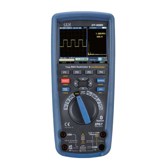
- Page 1 True RMS Multimeter & Oscillometer User Manual Meterbox User’s Guide Meterbox MODEL: MODEL: DT-9989 DT-9989 Please read this manual before switching the unit on. Important safety information inside. www.cem-instruments.com...
-
Page 3: Table Of Contents
Contents Contents True RMS Multimeter ....................... 1.Introduction........................2.Safety..........................3.Safety Instructions......................4.Feature .......................... Measurement and Setup....................6.General Specification s....................7.Specifications........................ Oscilloscope Section ....................1.Introduction........................2.Function and Operation....................3.Examples........................4.Fault Processing......................Appendix 1:Daily maintenance..................Appendix 2:Specifications....................Meterbox User’s Guide ................... 1.Meter Operation......................2.Meter Connection...................... -
Page 5: True Rms Multimeter
True RMS Multimeter MODEL: MODEL: DT-9989 DT-9989 Please read this manual before switching the unit on. Important safety information inside. www.cem-instruments.com... -
Page 6: Introduction
True RMS Multimeter 1.Introduction 9989 Professional True RMS Industrial Digital Multimeter with oscilloscope functions and TFT color LCD display ,providing fast A/D conver ting sampling time, high accuracy , built-in datalogging and Trend Capture feactures. It can trace any interrupted problems of the equipments and watch on without person. -
Page 7: Safety Instructions
True RMS Multimeter OVERVOLTAGE CATEGORY II Equipment of OVERVOLTAGE CATEGORY II is energy-consuming equipment to be supplied from the fixed installation. Note – Examples include household, office, and laboratory appliances. OVERVOLTAGE CATEGORY III Equipment of OVERVOLTAGE CATEGORY III is equipment in fixed installations. Note –... -
Page 8: Feature
True RMS Multimeter 3-7.NEVER operate the meter unless the back cover and the battery and fuse covers are in place and fastened securely. If the equipment is used in a manner not specified by the manufacturer, the protection provided by the equipment may be impaired. 4.Feature 4-1.Understanding the Push Buttons The 12 push buttons on the front of the Meter... - Page 9 True RMS Multimeter 4-2.Understanding the Display 13:17 - 0 0 0 0 8 03/26/11 Auto Range 0 0005 23.2 MENU SAVE REL,% SETUP .Soft key labels Indicates the function of the button just below the displayed label. .Bar graph Analog display of the input signal(See the "Bar Graph" section for more information). .Minus sign Indicates a negative reading.
- Page 10 True RMS Multimeter 4-4.Page Area The page area of the display is where the main meter content is displayed. The primary display (upper half of the page area) is where the most important value of the selected function is shown. The secondary display contains the bar graph and values that may be measured in addition to the primary function value.
-
Page 11: Measurement And Setup
Do not measure DC voltages if a motor on the circuit is being switched ON or OFF. Large voltage surges may occur that can damage the meter. 1 Set the function switch to the green VDC DT-9989 position. 8:10pm 06/13/07 auto range 100.00... - Page 12 CAUTION: Do not measure AC voltages if a motor on the circuit is being switched ON or OFF. Large voltage surges may occur that can damage the meter. 1.Set the function switch to the green VAC DT-9989 position. 8:10pm 06/13/07 auto range 2.press the soft key labeled Menu.
- Page 13 True RMS Multimeter 5-3.Making dB Measurements The Meter is capable of displaying voltage as a dB value, either relative to 1 milliwatt (dBm), a reference voltage of 1 volt (dBV) or a user-selectable reference value. 1.Set the function switch to the green VAC position.
- Page 14 Do not measure mV voltages if a motor on the circuit is being switched ON or OFF. Large voltage surges may occur that can damage the meter. 1.Set the function switch to the green mV position. 2.Press the soft key labeled Menu. DT-9989 8:10pm 06/13/07 auto range Move the menu selector to the menu item mVAC 500.00...
- Page 15 True RMS Multimeter 5-6 Temperature Measurements 1.Set the function switch to the green DT-9989 TEMP( C or F) position. ° ° 8:10pm 06/13/07 auto range °C 100.00 2.press the soft key labeled Menu. Move the menu selector to the menu item labeled TEMP .
- Page 16 Remove the batteries and unplug the line cords. 1.Set the function switch to the green Ω CAP position. DT-9989 2.Insert the black test lead banana plug into 8:10pm 06/13/07 auto range M Ω...
- Page 17 To avoid electric shock, disconnect power to the unit under test and discharge all capacitors before taking any resistance measurements. Remove the batteries and unplug the line cords. 1.Set the function switch to the green DT-9989 Ω CAP position. 8:10pm...
- Page 18 True RMS Multimeter 5-10.Diode Test 1.Set the function switch to the green Ω CAP position. DT-9989 8:10pm 06/13/07 2.Press the soft key labeled Menu. Move the auto range 0.400 menu selector to the menu item labeled Diode. Press the soft key Diode.
- Page 19 WARNING: To avoid electric shock, disconnect power to the unit under test and discharge all capacitors before taking any capacitance measurements. Remove the batteries and unplug the line cords. 1.Set the rotary function switch to the green DT-9989 Ω CAP position. 8:10pm...
- Page 20 30 seconds may cause damage to the meter and/or the test leads. 1.Insert the black test lead banana plug into the negative COM jack. μ 2.For current measurements up to 5000 A DC, DT-9989 μ 8:10pm 06/13/07 set the function switch to the yellow A auto range 10.000...
- Page 21 CAUTION: Do not make 10A current measurements for longer than 30 seconds. Exceeding 30 seconds may cause damage to the meter and/or the test leads. 1.Insert the black test lead banana plug into the negative COM jack. DT-9989 μ 8:10pm 06/13/07 2.For current measurements up to 5000 A AC,...
- Page 22 True RMS Multimeter 5-14.Understanding Function Menus Each primary measurement function (rotary switch position) has a number of optional sub-functions or modes accessed by pressing the softkey labeled Menu (F1). A typical menu is shown in Figure. Menu selection is indicated by the filled-in black square(hereafter the menu selector) to the left of a menu item.
- Page 23 True RMS Multimeter 5-16.Measuring AC and DC Signals The Meter is capable of displaying both AC and DC signal components (voltage or current) as two separate readings or one AC+DC(RMS) value combined. As shown in Figure , the Meter displays ac and dc combinations two ways: DC displayed over AC (DC,AC), and AC combined with dc (AC+DC).
- Page 24 True RMS Multimeter To save the MIN MAX screen data, the MIN MAX session must be ended by pressing the softkey labeled Stop. Next, press the softkey labeled Save.A dialog box openswhere the default saved name can be selected or anothername assigned. the softkey labeled Save to store.
- Page 25 True RMS Multimeter 5-22.Storing Individual Measurement Data For all measurement functions, a snapshot of the screen data is saved by pressing the softkey labeled Save. Edit name, then pressing the softkey labeled Save stored date. 5-23.Viewing Memory Data Viewing data stored in the Meter’s memory is performed through the save menu. Press the softkey labeled Save.
- Page 26 True RMS Multimeter 5-25.Recording Measurement Data The Meter’s record feature collects measurement information over a user-specified duration. This collection of information is called a recording session. A recording session is made up of one or more measurement records Each record contains measurement summary information covering the duration of the record.
- Page 27 True RMS Multimeter 5-27.Changing Meter Setup Options The Meter has a number of preset features such as date and time formats and battery save mode timeouts, and the displayed language. These variables are referred to as Meter setup options. Many setup options affect general Meter operations and are active in all functions. Others are limited toone function or group of functions.
- Page 28 True RMS Multimeter 5-32.Using Communications ou can use the Wireless communication link and transfer the contents of a meter’s memory to a PC. Press the softkey labeled Setup to access the setup menu. Using the cursor buttons, move the menu selector next to the menu item labeled communicate and press the softkey labeled PC. press the softkey labeled open will start communications function;...
- Page 29 True RMS Multimeter 5-37.Replacing the Fuses Referring to Figure , examine or replace the Meter's fuses as follows: 1.Turn the Meter off and remove the test leads from the terminals. 2.Remove the battery door assembly by using a standardblade screwdriver to turn the battery door screw one-half turn counterclockwise.
-
Page 30: General Specification S
True RMS Multimeter 6.General Specification Enclosure Double molded, waterproof Shock (Drop Test) 6.5 feet (2 meters) Diode Test Test current of 0.9mA maximum, open circuit voltage 3.2V DC typical Continuity Check Audible signal will sound if the resistance is less than 25 (approx.), test current <0.35mA Ω... - Page 31 True RMS Multimeter μ Fuses mA, A ranges; 0.5A/1000V ceramic fast blow A range; 10A/1000V ceramic fast blow Operating Temperatur 5°C to 40°C 41°F to 104°F Storage Temperature -20°C to 60°C -4°F to 140°F Operating Humidity Max 80% up to 31°C 87°F ) decreasing linearly to 50% at...
-
Page 32: Specifications
True RMS Multimeter 7.Specifications Function Range Resolution Accuracy DC Voltage 50mV 0.001mV (0.05% + 20) 0.01mV (0.025% + 5digits) 500mV 0.0001V (0.025% + 5digits) 0.001V (0.025% + 5digits) 0.01V (0.05% + 5digits) 500V 0.1V (0.1% + 5) 1000V [1] Add 10 counts by temperature influence. [2] Add 4 counts by temperature influence. - Page 33 True RMS Multimeter Function Range Resolution Accuracy μ μ DC Curren 0.01 A 0.1%+20 μ μ 5000 A 0.1 A 50mA 0.001mA 500mA 0.01mA 0.15%+20 0.001A 0.3%+20 (20A: 30 sec max with reduced accuracy) Function Range Resolution Accuracy C Curren 50 to 10000Hz μ...
- Page 34 True RMS Multimeter Function Range Resolution Accuracy AC Voltage 5K-100K (5000+Count) 50mV 0.001mV (5.0% + 40) 500mV 0.01mV 0.0001V 0.001V (6.0% + 40) NOTE: Accuracy is stated at 18 to 28°C 65 to 83°F ) and less than 75%RH. AC switch according to the calibration of sine wave. It generally increase ±...
- Page 35 True RMS Multimeter Function Range Resolution Accuracy Frequency 50Hz 0.001Hz ±(0.01% + 10) (electronic) 500Hz 0.01Hz 5kHz 0.0001kHz 50kHz 0.001kHz 500kHz 0.01kHz 5MHz 0.0001MHz 10MHz 0.001MHz Sensitivity: 0.8V RMS min. @ 20% to 80% duty cycle and <100kHz; 5V RMS min @ 20% to 80% duty cycle and >100kHz.
- Page 36 True RMS Multimeter...
-
Page 37: Oscilloscope Section
Oscilloscope Section MODEL: MODEL: DT-9989 DT-9989 Please read this manual before switching the unit on. Important safety information inside. www.cem-instruments.com... - Page 38 Oscilloscope Section Introduction Digital Oscilloscope, is of compact size, powerful and easily operated; TFT color LCD display, realizing its ease of use which can greatly improve customer’s work efficiency. Digital Oscilloscope performs outstandingly, powerful, affordable, with a high cost performance. Its real time sample rate is up to 50 MSa/s, can meet the market needs of high capture speed, complicated signal;...
- Page 39 Oscilloscope Section General safety requirements Know about the following safety precautions to avoid personal injury, also to prevent damage generated by connection of this product with any other product. In order to avoid any potential danger, please use the product according to the regulation. Only qualified technical personnel can take the maintenance procedures.
-
Page 40: Introduction
The following content makes a brief description and introduction of operation procedures and functions of the meter front panel, enable the user to be familiar with the meter in minimal time. DT-9989 Digital Oscilloscope provides a simple but with clear function front 8:10pm... - Page 41 Oscilloscope Section 1. Date and time 2. Status of current waveform windows 3. Remaining power of battery 4. Waveform display area 5. Waveform peak value 6. Signal coupling marks, preset amplitude gear 7. Waveform measured frequency 8. Preset sample rate 9.
-
Page 42: Function And Operation
Oscilloscope Section • To avoid electric shock, don’t touch the metallic part of the probe top while connecting to voltage source. • Measured signal by the oscilloscope is taken as a reference voltage to the ground, make sure the ground terminal connect to the earth correctly, do not cause a short circuit. 1 3 2 Probe application 1. - Page 43 Oscilloscope Section 2 2 Connector • Connector is adopted for the connection of probe and oscilloscope, the probe and connector must be used when the measuring frequency of waveform is above 1KHz. • When measured signal is a waveform of DC or its measuring frequency is below 1KHZ, the stick of general oscilloscope can be adopted.
- Page 44 Oscilloscope Section 2 5 Fast/slow display • When the measured signal is unstable, displayed waveform presents jumping; long-term observation may cause eye fatigue. Digital Oscilloscope offers the selection of fast/slow display function, press F3 (F/S), fast display can be switched to slow display, which can efficiently improve eye fatigue.
- Page 45 Oscilloscope Section 2-8 1 Trigger Mode • 2 kinds of trigger mode for the oscilloscope: raising edge and falling edge. When signal voltage across trigger electrical level, raising and falling edge of input signal is adopted for triggering. • Raising edge setup: press “setup” →...
- Page 46 Oscilloscope Section If adopt FFT (Fast Fourier Transform) mode, take following steps: 1. Set up time domain waveform • Press “AUTO” to display proper waveform. • If displayed waveform shows unsatisfactory, press “ ” and “ ” for adjustment. • Press F4 (FFT), the oscilloscope may adopt the 256 central points of time domain waveform to calculate FFT frequency spectrum.
- Page 47 Oscilloscope Section Note: • DC component or deviation existed in signal may cause error or deviation in FFT waveform component part. Select DC coupling mode to reduce AC component. • Nyquist frequency: for waveform, of which highest value ups to F, sampling rate of 2F must be adopted to rebuild the waveform, that is also called Nyquist criteria, “F”...
- Page 48 Oscilloscope Section 2-12 Display System 2 12 1 Time and Date •After startup, actual time and date display at the top left corner on the interface, format: mm/dd/yy, hh/mm/ss (picture 2-10-1). •Function of the clock is supplied by the back-up battery inside of the device, which can work for 5 to 10 years, and irrelevant to the Li-ion rechargeable battery.
- Page 49 Oscilloscope Section 4. Press F1 (V/F cursor), cursor measurement turns to voltage amplitude from frequency (cycle). Up and down cursor appears on the screen at the moment. 5. If use needs to move the cursor, press “ ”, one time for one space, press this key for more than 1 second for fast move, the cursor moves continuously in the same direction.
- Page 50 Oscilloscope Section 1. Store the current displayed waveform into the device. •Press “HOLD” “F2(Save)” enter into “Save Operations” state “ → → → ” (select position) → “F1(Memory)”, when no store exists in the position(No store), store directly, the color may turn to purple red from green if storage succeeds.
-
Page 51: Examples
Oscilloscope Section •Press F2 (return) under waveform displaying state, turn back to “Save Operations” state. •Press “F4 (EXIT)” in waveform displaying state, turn back to waveform displaying state. 3.Examples This chapter mainly introduces several application examples, these simplified examples focus on some main functions of the oscilloscope, and user may take it for reference to solve some actual testing problems. -
Page 52: Fault Processing
Oscilloscope Section 3 3 Serial Signal Measurement To measure serial signals, as UART, IIC, SPI and etc, please take following steps: 1. Take 3.1 operations as reference, preliminary observe the measured signal. 2. Press “REC” while signal transmission. 3. Press “NEXT” or “Previous” according to prompt bar on the screen to check corresponding page. - Page 53 Oscilloscope Section (5) Press “AUTO” to try again. 4.2 Waveform displays, but cannot stabilize. (1) Check the trigger option is correct or not. Waveform stabilizes only proper trigger mode is operated. (2) Try to change “trigger mode” to falling edge or raising edge, waveform can not stabilize in “no trigger”...
-
Page 54: Appendix 1:Daily Maintenance
Oscilloscope Section Appendix 1:Daily maintenance While store or place the device, please don’t make LCD display surface exposed to direct sunlight for long time. Note: to avoid device or probe damage, please don’t place it in fog condition, liquid or dissolvent. -
Page 55: Appendix 2:Specifications
Oscilloscope Section Appendix 2:Specifications Main specification Format or note Function 3.5” color TFT-LCD; 320 X 240 pixels LCD display 15~50 V/S Fast / Slow Refresh rate 10MHz 0 - 10 MHz Bandwidth Coupling, AC, DC AC DC , Input Ω Input impedance 1000C/CA:1M +/-2%... - Page 56 Oscilloscope Section...
-
Page 57: Meterbox User's Guide
Meterbox User’s Guide Meterbox www.cem-instruments.com... - Page 58 Meterbox User’s Guide Meterbox is a kind of smart mobile software for meter’s cloud computing. Using this software, the measured data can be transmitted to smart mobile via Bluetooth. Users can share the meter data with the cloud storage and cloud computing of the meters’ cloud service by a smart mobile. These can satisfy the continuous growing on-demand of business in the mobile era, and help users to achieve the functions which other meters can’t realize.
-
Page 59: Meter Operation
Meterbox User’s Guide d. Meter Cloud Computing: Large number works of computing and storage can be accomplished in meter cloud server, and the user's business computing can be added and deleted through the network, therefore, mobile can break through the limit of software function, computing power, storage capacity to achieve the powerful calculation and storage function as a mainframe. - Page 60 Meterbox User’s Guide Function Selection interface will be shown after choosing the right meter. Click , (the meter enter into Bluetooth mode), Meterbox will match with Bluetooth.
-
Page 61: Measurement Mode
Meterbox User’s Guide When matching successfully, Meterbox combined with the meter to be a Cloud Meter. 3 Measurement Mode Meterbox Cloud Meter supports the following measurement mode: * Local meter measuring * Cloud meter measuring In Login interface, users click Login to enter Cloud meter measuring; while click Local to enter Local meter measuring. -
Page 62: Connect Meter Cloud
Meterbox User’s Guide a. Local meter measuring: When the user in an area without signal coverage (GPRS/3G/WiFi), or just want to operate in local mode, users enter local measuring mode. In local mode, data measured by the meter transmitted to Meterbox via Bluetooth and stored in the storage medium of the smart mobile. As the limitation of storage and computing capacity of a phone, Meterbox cloud function can not be achieved. -
Page 63: Data Recording
Meterbox User’s Guide 5 Data Recording To record data, please enter the Meterbox’s Function Selection interface. Click , the meter will connect with mobile via Bluetooth, measured data could transmit to Meterbox data display interface in real-time. -
Page 64: Data Chart
Meterbox User’s Guide When users need to record data, press button to begin recording in real-time, the prompt can check current recording. To terminate data recording, re-click , the meter data recording completed. In local mode, data stored in cell phone, while in cloud mode, data transmit to meter cloud sever in real-time. - Page 65 In statistical interface, users can check the detail mathematical statistics information of the measured data, including sampling point, sampling rate, Min/Max, average value etc. Project Project Name:Oscilloscope User Name:aaaaaa Multimeter:DT-9989 First Time:08/24/2011 16:51:48 Last Time:..MerterID:00:1F:B7:03:C7:61 Statistics Sample count Time ramge ..
-
Page 66: Data File
Meterbox User’s Guide 7. Data File To check the data file, users can enter Meterbox Function Selection interface, choose button In the interface of data file list, all the buffered measure data in local database will be shown. Data measured by local mode, the front of the data file will shown icon , indicate the data have not synchronized in the meter cloud sever, on the contrary, the front of the data file shown icon... -
Page 67: Data Sharing
Meterbox User’s Guide Data Sharing Users can export measured data from Meterbox for other statistics analysis or producing professional report etc. To export the data, first press the button on the mobile in the chart interface, will popup menu, users can click Save As Picture , or Save As CSV. - Page 68 SHENZHEN EVERBEST MACHINERY INDUSTRY CO.,LTD. Nanshan, Shenzhen China P .C. 518108 www.cem-instruments.com Rev.111213...
Need help?
Do you have a question about the DT-9989 and is the answer not in the manual?
Questions and answers