
Related Manuals for IS Technologies SLM600 Plus Series


Summary of Contents for IS Technologies SLM600 Plus Series
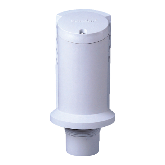
- Page 1 Ultrasonic Level Meter SLM600 Plus Series (User’s Manual) IS Technologies Co., Ltd.
- Page 2 IS Technologies Co., Ltd. guarantees for a period of 1 year from the date of delivery that it will either exchange or repair any part of this product returned to IS Technologies Co., Ltd. if it is found to be defective in material or workmanship, subject to the defect not being due to unfair wear and tear, misuse, modification or alteration, accident, misapplication or negligence.
-
Page 3: Table Of Contents
Contents Chapter 1 Start Here…....................................4 About this Manual......................................4 About the SLM 600 Level Monitoring System............................5 Functional Description....................................5 Product Specification....................................6 Chapter 2 Installation ....................................7 Power Supply Requirements ..................................7 Terminal Connections..................................... 10 Preparation for Operation ..................................11 Maintenance ......................................11 Chapter 3 How To Use Your SLM 600 Level Monitoring System ....................... -
Page 4: Chapter 1 Start Here
Chapter 1 Start Here… Congratulations on your purchase of a Sondar Ultrasonic Level Meter 600 Series. This quality system has been developed over many years and represents the latest in high technology ultrasonic level measurement and control. It has been designed to give you years of trouble-free performance, and a few minutes spent reading this operating manual will ensure that your installation is as simple as possible. -
Page 5: About The Slm 600 Level Monitoring System
About the SLM600 Series Functional Description The Sondar SLM600 Series is a highly developed ultrasonic level measurement system which provides non- contacting level measurement for a wide variety of applications in both liquids and solids. Easy calibration and maintenance free “fit and forget” performance mean that you can install the SLM600 Series rapidly and with confidence. -
Page 6: Product Specification
Product Specification Physical Dimensions overall 105 (dia). x 248.5 (height) mm electronics housing 105 (dia). x 172 (height) mm transducer housing 55 (dia) x 76.5 (height) mm mounting 2” NPT Weight Nominal 1 kg Case material/description Polypropylene Cable entry detail 1 x PG11 at rear (fitted with gland) Environmental IP Rating (electronics housing) -
Page 7: Chapter 2 Installation
Chapter 2 Installation Power Supply Requirements The SLM600 operates from a DC supply of 20 –30V and will typically draw less than 0.08A. All electronic products are susceptible to electrostatic shock, so follow proper grounding procedures during installation. The compact one-piece construction of the SLM600 can be mounted easily using the integral nose thread (2”NPT). - Page 8 Outdoor and Open Vessel Installation The SLM600 can be simply mounted on a bracket, suitable for the application and secured using the thread located at the top of the transducer (2”NPT). Care should be taken to ensure that the SLM600 is not installed in direct sunlight, in order to avoid errors in the measurement of ambient temperature.
- Page 9 Stand Pipe Installations When mounting the SLM600 to a standpipe care should be taken to ensure that the standpipe is of sufficient dia with reference to its length, see the table below for details: D(mm) Length(mm) L(mm) D(mm) When using a standpipe, fixed to the top of a vessel, ensure that the open end of the standpipe is clear of any obstructions such as weld seams, gaskets etc.
-
Page 10: Terminal Connections
Cable Entry The SLM600 Series has a single PG9 cable entry, fitted with a suitable gland, to ensure moisture protection is maintained. Terminal Connection Details The SLM600 Series comes in both 2 wire and 3 wire versions the terminal connections for both are as detailed below. -
Page 11: Preparation For Operation
There are no user serviceable parts inside your SLM600, if you experience any problems with the unit, then please contact IS Technologies Co., Ltd. for advice. To clean the equipment, wipe with a damp cloth. Do not use any solvents on the enclosure. -
Page 12: Chapter 3 How To Use Your Slm 600 Level Monitoring System
Chapter 3 How To Use SLM600 Series Operating the Controls Display Whilst in the Run Mode, the 3-digit LCD display will show the current level reading in centimetres, it will also display a flashing “0” when a fault condition (Loss Of Echo) is detected. When in the Program Mode the display is used to read information on the Menu Options and the values entered. -
Page 13: Program Mode
Program Mode This mode is used to set up the SLM600 or change information already set, this is achieved by using the 4 push buttons located either side of the display. Entering a value for each of the menu options that are relevant to your application provides all the programming information. - Page 14 Example of using bottons Press the Mode button to enter the program mode. Option No. is displayed. To check the option value, press the Up button The present value is displayed. Press the Up button to change the value The value is changed. Press the Mode button to advance to next option The next option No.
- Page 15 The option No. of next option group is displayed. Press Mode button to enter into next option The option No. is displayed. Press Up button to check the option value Page...
-
Page 16: What To Do First
LED Functions There are 4 LED’s, located above the display their functions are as follows: Condition Function Detect Indicates Normal Operation Flashing & together Mode selected = Level Level Detect Indicates Normal Operation Flashing & together Mode selected = Distance Distance Detect Indicates Normal Operation... -
Page 17: Chapter 4 Menu Guide
Chapter 4 Program This chapter describes all of the menu options in your SLM600, in numerical order. Application Menu Options 01 Operating Mode Factory Set = 1 Level This option sets the mode of operation when in run mode, and can be set to one of the following: Option Description 1= Level... -
Page 18: Current Output Menu Options
Current Output Menu Options 11 4 mA Setpoint Factory Set = 0 This option sets the distance (or level or space, depending on the selected Operating Mode (Option 01) at which the 4mA output will occur. By default 4mA will represent Empty (0% of Span) 12 20 mA Setpoint Factory Set = Span This option sets the distance (or level or space), depending on the selected Operating Mode... -
Page 19: Compensation Menu Options
Compensation Menu Options 21 Damping Rate Factory Set = 2 This option determines the maximum rate at which the unit will respond to an increase/decrease in level. Option Description 1 = 0.1m/min Responds to changes to a max. 0.1m/min 2 = 0.5m/min Responds to changes to a max. - Page 20 24 Sound Velocity Factory Set = 332 m/sec This option allows for the velocity of sound to be changed according to the atmosphere the transducer is operating in. By default the velocity is set for sound travelling in air at a temperature of 0 The table below gives details of the velocity of sound in various gaseous atmospheres In all cases the velocity indicated is that in a 100% gaseous atmosphere at 0...
-
Page 21: Output Simulation Menu Options
Outputs Simulation Menu Options These menu options are used when the SLM600 operates with other field instruments. Option No. 32, 33 is only for 3 wire version. 31 Display value simulation This option simulates display output value at user’s need compulsory. The range of simulation values is empty value set at Option No.4 32 Limit 1 output simulation Factory Set = 0... - Page 22 Switched Outputs Menu Options This option group displays only at 3 wire version 51 Limit 1 ON Setpoint Factory Set = 100cm (39) This option determines the “ON” point for L1 Switched Output (NPN Open Collector). Setpoints are entered in centimetres measured from the Empty Level. 52 Limit 1 OFF Setpoint Factory Set = 110cm(43) This option determines the “OFF”...
-
Page 23: Chapter 5 Troubleshooting
Chapter 5 Troubleshooting This section describes some problem symptoms, with suggestions as to what to do. Symptom What to Do Display blank, transducer not firing. Check power supply No valid echo being received and unit has gone into fault condition. Display shows flashing “0”... -
Page 24: Menu Option Record
Menu Option Record SLM600 Series (2 and 3 wire) APPLICATION Option Details Entered Values Description Factory Set Operating Mode 1 = Level System Unit 1 = cm Display 1 = cm(inch) Empty Level Empty Dist. Blanking Distance 30cm(12 inches) CURRENT OUTPUT 4mA Setpoint 20mA Setpoint mA Fail Safe Value...
Need help?
Do you have a question about the SLM600 Plus Series and is the answer not in the manual?
Questions and answers