
Related Manuals for High Tech Pet BE-500


Summary of Contents for High Tech Pet BE-500
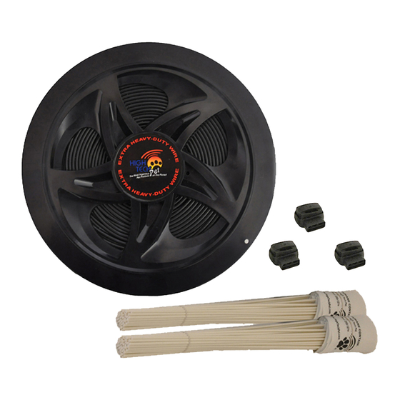
- Page 1 BE-500 Wire and Flag Kit INSTALLATION OPERATING GUIDE Please read this entire manual and study all illustrations before you begin installing your system...
-
Page 2: Boundary Wire
BOUNDARY WIRE Even the boundary wire used on your X-30, HC-8000, HC-7000 or X-10 system is unique. The copper alloy wire and insulating coating are all made specially to our custom specifications. We have designed it to be an efficient radio frequency broadcast conductor, with a mechanically strong core and an extra thick, extra tough, outdoor grade insulation that resists sunlight and moisture. - Page 3 TYPICAL LAYOUT FOR BOUNDARIES WITHIN BOUNDARY Twisted To Pond Twisted To Pool Pool Garage Boundary Wire Twisted Property Line Wire Transmitter Mounted in Garage Splice Splice Twisted Wire Cancels Field Figure 6...
- Page 4 Calculate the total length of wire required to ensure that you have enough to complete the installation. Remember that twisted wire counts as twice its length since there are two strands. Figure 7 shows a basic wire length calculation. In preparing your layout, note that you will need to allow for a field width of at least 3 feet (preferably 6 –...
- Page 5 For the system to work properly, the wire must make a continuous loop. The signal is transmitted from one terminal of the transmitter through the wire and back to the other terminal. Twisting two adjacent sections of the wire loop cancels the signal along the twisted length. So, use the twisted wire from the transmitter out to the exterior loop as shown in Figure 8.
- Page 6 Adding a GATE MAKING A CONTAINMENT FIELD WITH A GATE If you want a permanent opening or WIDE gate in the containment field, you must use GATE what is commonly called a double loop, as shown in Figure 9. Carefully follow Wire Wire the current around the wiring and you...
- Page 7 TIP: The amount of twist and the direction of the twist is of little importance, as long as the wires are touching each other along the entire “gate” section.
- Page 8 DO NOT DO THIS! A VERY COMMON ERROR A common error is trying to replace a section of single loop wire with a piece of twisted wire to create a gate as shown in INCORRECT Figure 11. This will not SINGLE SECTION OF WIRE LOOP work.
- Page 9 STEP 2: Assemble the Required Tools Here is the list of tools you will need. 1. Straight edge spade or power edger 2. Wire cutter/stripper STEP 3: Prepare Twisted Wire Lengths First Prepare the twisted lengths of wire. From your system layout sketch, determine the length required for each twisted pair.
- Page 10 Splicing the Boundary Wire: You may find the included improved waterproof wire splices useful in connecting individual lengths of wire or twisted wire. To use these connectors: Push the two ends of the wires into the outer two holes in the splice. View from the bottom to make sure the wires are fully inserted.
- Page 11 Place the wire in the slit and seal with outdoor silicone caulk of matching color. Use asphalt sealant for asphalt driveways. Another option is High Tech Pet’s new optional Driveway Traverse Strip, which easily crosses driveways and walks with your electronic fence wire. This durable rubber slit attractively covers and protects the pet fence wire.
- Page 12 Crossing Gravel When crossing gravel, run the wire through a hose or PVC pipe and then bury at least three inches deep. Crossing Water To cross a stream or body of water, run the wire through a hose or PVC pipe. Anchor each end using large rocks or other stationary objects.
-
Page 13: Troubleshooting Procedures
TROUBLESHOOTING PROCEDURES If any part of the system is not working use the following troubleshooting procedure to isolate the failed component. Then contact High Tech Pet Products Customer Support to get it repaired or replaced. Test Base Station Transmitter First disconnect the boundary wire loop from the... - Page 14 Station Transmitter are OK, and only the first collar is failed – repair or replace just the first collar. If you have a friend who also owns a High Tech Pet , Humane • Contain system that is working, test your collar(s) on their operating system by holding your collar next to their collar in the yard.
- Page 15 Test the Containment Loop h) Once you have verified the components are working using steps 1) and 2.) above, disconnect the Test Loop Wire and re- connect the containment wire loop to the Base Station Transmitter. Place the working collar on the ground about five feet from the wire, in a “clean”...
-
Page 16: Warranty & Customer Support
system are working properly. If not, the loop is intermittent. Go to step 4). Repairing a Broken or Intermittent Containment Loop There are many ways to approach repairing a faulty loop depending on the length of wire, the number of connections, the terrain, available equipment, etc. - Page 17 High Tech Pet Products, Inc. 2111 Portola Rd., Suite A Ventura, CA 93003 www.hightechpet.com...
Need help?
Do you have a question about the BE-500 and is the answer not in the manual?
Questions and answers