
Related Manuals for MicroBT WhatsMiner M10S


Summary of Contents for MicroBT WhatsMiner M10S
- Page 1 Whats Miner M10S Operation Guide V1.1 (Simplified Version) Shenzhen MicroBT Electronics Technology Co.,Ltd...
-
Page 2: Table Of Contents
1. M10S Product Introduction......................3 2.Whats Miner Connection and Racking Safety Notes..............3 2.1.Miner Connection Notes.....................3 2.1.1.Power Supply Control Wire Connection Notes ............4 2.1.2.Adapter Board Control Wire Connection Notes............4 2.1.3.Fan Connection Notes....................6 2.1.4.Hash Board and Adapter Board Connection Notes..........8 2.1.5.Power Supply Copper Busbar Connection Notes.............9 2.1.6.Product Connection Check..................10 2.2.Miner Handling and Racking Notes...................11... -
Page 3: M10S Product Introduction
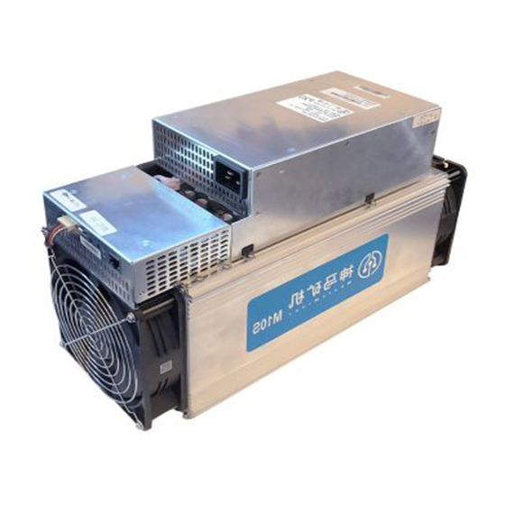
1. M10S Product Introduction Whats Miner M10S Bitcion Mining Magic Product ParameterIntroduction as below: HashRate:55TH/s ±5% Chip:555pcs 16nm ASIC Power:3450W±10% Power Rate:63W/T ±10% Power Supply:Whats Miner Power Supply P10(220v,3450W ±10%) Control Panel:Own Environment Temperature:-5℃~40℃ Product Size:385mm*155mm*239mm 2.Whats Miner Connection and Racking Safety Notes 2.1.Miner Connection Notes Check over the miner’s power supply control wire and adapter board control wire... -
Page 4: Power Supply Control Wire Connection Notes
not be covered by the warranty. When connecting the wiring of the control board, the clasp must be corresponding, and the pin cannot be inserted into the socket by force.If the backplug, the power may burn the control board, burning the signal wire! 2.1.1.Power Supply Control Wire Connection Notes The power control wire is 14pin, and the card slot is inserted relative: Correct Connection:... - Page 5 Incorrect Connection:...
-
Page 6: Fan Connection Notes
2.1.3.Fan Connection Notes The fan wire is 6pin, and the card slot is inserted relative: Correct Connection:... - Page 7 Incorrect Connection:...
-
Page 8: Hash Board And Adapter Board Connection Notes
2.1.4.Hash Board and Adapter Board Connection Notes The socket of the adapter board and the pin of the hash board must be installed in place to avoid other problems caused by contact problems! Correct Connection: Incorrect Connection:... -
Page 9: Power Supply Copper Busbar Connection Notes
2.1.5.Power Supply Copper Busbar Connection Notes When the power supply copper busbar is connected to the hash board, the positive and negative poles of the copper busbar cannot be connected incorrectly, and the screw washers of the fixed copper bar must be aligned in parallel with the edge of the copper bar. -
Page 10: Product Connection Check
Incorrect Connection: 2.1.6.Product Connection Check After all the connections of the miner are connected and all the screws are tightened, check again to confirm that the connection is correct. -
Page 11: Miner Handling And Racking Notes
2.2.Miner Handling and Racking Notes In the process of handling and racking of the miner, it is strictly forbidden to use the data cable, the power supply control wire and the fan wire as the load- bearing handle of the miner, and to pick up the machine and the power supply. Lifting the machine and power supply through the connection will result in damage to the connection, loose connection, and physical damage to the control panel beyond its capacity. -
Page 12: Miner Configuration Environment Preparation
3. Miner Configuration Environment Preparation 3.1.Miner Configuration Equipment List Tool Numb Remark Computer Miner configuration Miner Power Power the miner Supply Configuring miner and The switch can Switch configuration computer connect to the network communication Internet. 1、Provide a dynamic IP It defaults to DHCP address for the initial DHCP/NTP... -
Page 13: Miner Connection And Pre-Power Check
correctness of the calculation statistics, etc. depend on the network NTP time. The mining machine itself is configured with multiple NTP server addresses of the public network by default. In order to speed up the acquisition of network time and improve the time precision, it is recommended to mine the network. -
Page 14: Miner Data Configuration(Configuration On The Web
must be connected. Otherwise, the power supply voltage output may not be controlled, resulting in low power calculation. (3)The control board must be connected to the fan wiring reliably. If the fan wiring is disconnected or the connection is poor, the miner may not be able to cool down, the power board is down-converted, and the power is reduced. - Page 15 (2)View the dynamically obtained IP, MAC address, and miner position reported by the machine in WhatsMinerTools software. Notes: (1)If all the lights on the panel of the machine control panel are not lit after power-on, please check whether the power supply of the 220V power cable and the 16A power cable are reliable and the connection is correct.
-
Page 16: Configuration Pool&Worker Data And Ntp Server Address
(4)If the computer and the mine machine are on the same network segment, and the DHCP service is enabled in the network, after the mining machine ipfound button, WhatsMinerTools software does not query the IP of the machine, long press the reset button on the machine panel for more than 5s to recover Factory default configuration, then power off the mine machine and then power on and restart, power on 30s and then press the ipfound button to detect the mine IP address. - Page 17 After the configuration of the mining pool is modified, the modified configuration must be restarted after the cgminer program is restarted or the control panel is restarted. (3)Restart cgminer to check whether the configuration modification takes effect. In the miner interface, select: Status-"CGMinerStatus" to enter the CGMiner running status interface.
-
Page 18: Modify The Ntp Synchronization Server Address (Optional)
(4)Restart the control board and check whether the configuration modification takes effect. (If you do not choose to restart cgminer, after the configuration is modified and saved, you can also restart the control board to make the configuration take effect.) In the system interface,click on”Reboot”. -
Page 19: Configuration The Static Ip Address (Optional)
(2)In the cgminer configuration interface, add or modify the NTP server address. The miner has been configured with four NTP server addresses by default. You can modify or add the NTP server address to the local NTP server address according to the mine situation. - Page 20 After logging in to the machine, in the miner interface, select: Configuration- (2) >Interfaces to enter the network interface configuration interface. In the "Configuration" interface, click "Edit". (3) In the interface modification page, select "Static address" for the protocol and click (4)...
- Page 21 (5)In the static address configuration interface, change the IP address, mask, gateway, broadcast address, and DNS address to the actual planned address of the mine. After editing, click "Save & Apply" in the lower right corner. After saving the application, you need to re-use the newly set static IP address to log in to the mining machine (otherwise the page will display loading until the loading fails).
-
Page 22: Miner Operation Status Check
6.Miner Operation Status Check After the mine is connected to the operation network, log in to the machine and check the running status of the machine. (1)In the miner interface, select: Status->CGMiner Status to enter the cgminer running status interface. (2)View the overall calculation of the mining machine, front and rear fan speed, connection to the mining pool, single board computing power, board temperature and other operating conditions. - Page 23 Notes: (1)The mining machine is connected correctly. When the network is normal, the mining machine will automatically perform the frequency search test after power-on. The search frequency test phase takes about 15 minutes. After the search frequency is over, it will enter the formal mining stage.
-
Page 24: Miner Batch Data Configuration, Miner Status Check, Firmware Upgrade
7.Miner Batch Data Configuration, Miner Status Check, Firmware Upgrade You can use the WhatsMinerTool software to carry out batch data configuration, status check and firmware upgrade of the mining machine. For details, please refer to the "Whats Miner WhatsMinerTool Operation Guide". 8.Miner Disassembly and Installation 8.1. - Page 25 3)Unplug the power control cable and the adapter board control cable connected to the control panel as shown: 4)Remove the four screws fixed on the bracket and take out the control panel from the bracket as shown:...
-
Page 26: Control Panel Installation
8.1.2.Control Panel Installation 1)When installing the control board, first fix the 4 screws on the control board bracket, as shown in the figure: 2)Insert the power control cable and the adapter board control cable into the corresponding slots on the control board, and then fix the bracket to the chassis with... - Page 27 screws, as shown in the figure: 3)Plug the fan cable and the control board is installed.
-
Page 28: Power Supply Disassembly And Installation
8.2.Power Supply Disassembly and Installation 8.2.1.Power Supply Disassembly 1)Remove the four screws that secure the power supply on the chassis (see Figures 1, 2, 3, and 4), and then remove the six screws that secure the copper bars on the power supply (Figure 6). -
Page 29: Power Supply Installation
3)Unplug the power control cable on the control panel, remove the power supply, and remove the power supply: 8.2.2.Power Supply Installation 1)First plug the control cable of the power supply into the corresponding slot on the control panel, as shown below:... - Page 30 2)Then connect the 6 positive and negative terminals on the power supply to the copper row one by one, and then install 6 screws in turn. The screws should be tightened and the gasket should be aligned parallel to the edge of the copper bar to avoid short circuit burning the power supply or the power board, as shown below:...
-
Page 31: Hash Board Disassembly And Installation
8.3.Hash Board Disassembly and Installation 8.3.1.Hash Board Disassembly 1)There are three hash boards on each mining machine (the order number of the hash board is as shown below). Before removing the board, first remove the control board and the inlet fan, as shown below: 2)Remove the adapter plate and the copper bar fixed to the control panel as shown:... - Page 32 3)Extract the faulty hash board outward, as shown: 4)After taking out the hash board, use WeChat “sweep” to scan the power board serial number and provide it to the relevant after-sales technician, as shown:...
-
Page 33: Hash Board Installation
8.3.2.Hash Board Installation 1)When the hash board is loaded into the chassis, one hand holds the board into the hash board slot, and sequentially enters the chassis, as shown in the figure:... - Page 34 2)After installing the hash board into the chassis, first install the adapter board. The socket of the adapter board and the pin of the hash board must be installed in place to avoid other problems caused by contact problems, as shown:...
- Page 35 After the adapter plate is installed, install the copper bar. When the power busbar is 3) connected to the hash board, the positive and negative poles of the copper bar cannot be connected incorrectly, and the screw pads of the fixed copper bar must be aligned with the edge of the copper bar, otherwise it may be possible to power on.
Need help?
Do you have a question about the WhatsMiner M10S and is the answer not in the manual?
Questions and answers