
Related Manuals for MicroBT Whats Miner M3


Summary of Contents for MicroBT Whats Miner M3
- Page 1 Whats Miner All-in-one machine operation instruction V1.2(H3 platform) (Lite version) Shenzhen MicroBT Electronics Technology Co., Ltd.
-
Page 2: Table Of Contents
目录 1. Introduction of M3 Integrated Machine..................3 2.Mine wiring, safety warning for operation on the shelf..............3 2.1.Matters needing attention in connection of Mine Machine..........3 2.1.1.Points for attention in connection of Control Panel 12V Power Line......4 2.1.2.Matters needing attention in connection of Power supply Control Line....4 2.1.3.Matters needing attention in connection of Fan Line.......... -
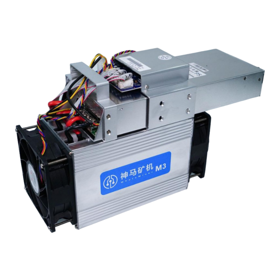
Page 3: Introduction Of M3 Integrated Machine
1. Introduction of M3 Integrated Machine Whatsminer M3 integrated machine Bitcoin miner The product parameters are as follows: Computational power: 12TH/S Chip: 189 28nm ASIC Power consumption: 0.18~0.19kw/TH Supporting Power supply: Shenma Power supply P5 (220vU 2250W) Control board: with ambient temperature: -5 ℃... -
Page 4: Points For Attention In Connection Of Control Panel 12V Power Line
force board burning, the whole machine and veneer will not belong to the scope of warranty! 2.1.1.Points for attention in connection of Control Panel 12V Power Line When connecting the power cord of the control board, the plug of the power cord and the clasp at the two ends of the power outlet of the control board must correspond to each other, and the plug of the power cord cannot be inserted into the control board socket by force. -
Page 5: Matters Needing Attention In Connection Of Fan Line
2.1.3.Matters needing attention in connection of Fan Line Fan line is 4pin blue, yellow and red black line, 4 small mouth outside, card slot relative bit insert:... -
Page 6: Matters Needing Attention In Data Wiring Connection Of Force Plate
2.1.4.Matters needing attention in data wiring connection of Force Plate 2.1.5.Matters needing attention in connection of 12V Power Line with Power Plate When connecting the power cord of the force board, the power cord connecting post and terminal must correspond to each other (yellow power cord is connected to the red cable, and the red pole is connected to the positive pole (V);). -
Page 7: Machine Wiring Inspection
2.1.6.Machine wiring inspection After all mine connections are connected, check again to confirm that the connection is correct. 2.2.Mining machine handling, on the shelf operation points for attention process machine handling loading, data wire arrangement, power control line, fan wire are strictly prohibited as lifting handle, lifting machine and power supply. -
Page 8: Mine Machine Configuration Environment Preparation
3. Mine machine configuration environment preparation 3.1.Mine machine configuration equipment list Serial Serial number Serial Serial number tool name Serial number tool number tool name numbe quantitative use remarks name quantitative use 1 computer 1 1 computer 1 mine tool quantitative use r tool remarks... -
Page 9: Mine Machine Connection And Check Before Power On
4.Mine machine connection and check before power on (1) before connection and electrification, the miner shakes the mine machine in accordance with the warning signs on the side of the mine machine to check whether any radiator or other device is off, to ensure that there is no radiator or other period of abscission before connection and power up. -
Page 10: Mine Data Configuration (Configured On The Web Page)
5.Mine data configuration (configured on the web page) 5.1.Query dynamic ip address obtained by mining machine 5.1.1.Running WhatsMinerTools Software The data of mine machine is configured with PC connected to the same network where the miner is located, running the WhatsMinerTools software on PC, selecting the "probe ip"... - Page 11 (2)In the WhatsMinerTools software to view the dynamic access to the mine machine reported IP,MAC address, mining machine location. Note: (1) if all the lights in the control panel of the mine machine are not on after the power is turned on, please check the 220V power supply line, the 12V power cord connection is reliable and the connection is correct.
-
Page 12: Mine Pool & Miner Data And Configuration Ntp Server Address
5.2.Mine Pool & Miner data and configuration NTP Server address 5.2.1.Mine Pool & miner disposition (1) after logging in, go to the Cgminer configuration page. (2) in the Cgminer configuration interface, modify mine pool address, miner name, and after modification, click "Save & Application" in the lower right corner to save the modified configuration. - Page 13 In the cgminer status interface, click RestartCGMiner to restart the cgminer process. (4) restart the control panel and check whether the configuration changes are effective. (if you do not choose to restart cgminer, configuration changes saved, you can also restart the control panel, so that the configuration takes effect) in the system interface, click "Reboot".
-
Page 14: Modify The Address Of The Ntp Synchronization Server (Optional)
login interface. 5.2.2.Modify the address of the ntp synchronization server (optional) (1) after login, select: Configuration- > CGMiner Configuration, in the interface to enter the Cgminer configuration page. (2) in the cgminer configuration interface, the address of four ntp servers has been configured by default when the ntp server address is added or modified, and the address of the ntp server can be modified or added to the local ntp server address according to the situation of the mine. -
Page 15: Configure Mine Machine Static Ip Address (Optional)
5.3. Configure mine machine static IP address (optional) The IP address obtained by mine machine DHCP is modified to static IP address of mine operation network planning. (1) input the queried mining machine dynamic ip, in the browser with root user, default password: root, login mine machine interface. - Page 16 (4) in the interface modification interface, the protocol (protocol) selects "Static address" and then clicks "Switch protocol". (5) in the static address configuration interface, the IP address, mask, gateway, broadcast address and DNS address are changed to the actual planned address of the mine.
-
Page 17: English And Chinese Language Switching Of Mining Machine Page
保存应用后,需要重新用新设置的静态 IP 地址才能登录矿机(否则一直页面显示 加载中直到加载失败)。 After saving the application, you need to re-use the newly set static IP address to log in to the mine machine (otherwise, the page appears loaded until the load fails). 5.4. English and Chinese language switching of Mining Machine Page 6.Mine machine running condition check After the ore machine is connected to the running network, log in the mine machine... - Page 18 Note: (1) if the connection of the mine machine is correct and the network is normal, the frequency search test will begin automatically after the mining machine is powered on. The frequency search test phase will take about 15 minutes. After the frequency search is over, it will only enter the formal mining stage.
-
Page 19: Batch Data Configuration, Status Check, Firmware Upgrade
force. (4) if the temperature is not detected in the state interface and the temperature is not detected, it is necessary to lower the electric power line of the mine machine and reinsert the power line of the corresponding force plate, and the two ends of the data wire arrangement (one end of the control board and one end of the force board) to ensure the reliability of the connection. - Page 20 After drawing, as shown in the figure: 2) Separate load plate connection columns are removed (at the outlet side) in turn, as shown in thefigure:...
- Page 21 After disassembly, as shown in the figure: 2) The third step is to remove the eight screws on both sides of the fixed power supply, as shown inthefigure:...
- Page 22 2).Pull out the power supply from left to right (note that the power cord is not broken), as shown in the figure: After the power supply is removed, the figure is as follows:...
-
Page 23: Installation Of Power Supply
8.1.2.Installation of power supply 1).1) when installing the power supply, fix the 4 screws of the control panel cover bracket first, then adjust the position of the armrest support and then tighten the screw, as shown in figure: 2) make sure to tighten the screws when connecting the bar with the terminal, otherwise it will affect the calculation force, as shown in figure:... -
Page 24: Disassembly And Installation Of Control Panel
3).The control board of the line corresponding to plug-in, the power installation is complete. 8.2.Disassembly and installation of Control Panel 8.2.1.Disassembly of control panel 1).1) remove the 2 screws of the fixed control and the 4 screws of the support of the fixed control plate respectively, as shown in the figure: 2)Remove the four baffle screws from the outlet of the fixed power supply, as shown in the figure:... -
Page 25: Installation Of Control Panel
2)Then move the control panel support from left to right, and the control panel is removed from right to left, as shown below: 8.2.2.Installation of control panel The mounting direction of the control panel is arranged in reverse order according to the control board removal, and the screws are tightened accordingly to prevent the control board from loosening. -
Page 26: Disassembly And Installation Of Force Plate
8.3.Disassembly and installation of Force Plate 8.3.1.Disassembly of force plate 1).There are three force plates on each machine, and the corresponding relationship between the control board and the control board is shown in the figure.: 2).To remove the problematic force plate, the four baffle screws and the corresponding connecting posts for the fixed outlet fan need to be removed, as shown in the figure:... - Page 27 3).After the connection column corresponding to the fan and the force plate is removed, the faulty force plate is extracted, as shown in the figure: 4).After taking out the force plate, use WeChat to scan the serial number of the force plate and provide it to the relevant after-sales technicians, as shown in the figure:...
-
Page 29: Installation Of Force Plate
8.3.2.Installation of force plate 1).1) when the force plate is loaded into the chassis, one hand holds the force board into the force board slot, a portable starting force board connecting column and the force board connection line, and the sequence enters the chassis, as shown in figure:... - Page 30 2).2) after the installation of the force plate, install the fan. When installing the fan, pay attention to the fan connection line on the right, be careful of the wrong direction, or you will need to reinstall, as shown in the figure:...
Need help?
Do you have a question about the Whats Miner M3 and is the answer not in the manual?
Questions and answers