
Subscribe to Our Youtube Channel
Related Manuals for AEROCOMPACT CompactFLAT SN10


Summary of Contents for AEROCOMPACT CompactFLAT SN10
- Page 1 CompactFLAT SN10 longside Assembly Instructions Version: 02/2021 Language: English | Original language: German Original installation instructions Important! Read carefully before installation!
- Page 2 The original language of these assembly instructions is German. Any assembly instructions in another lan- guage are a translation of the assembly instructions in German. The assembly instructions are protected by copyright. Without written permission from AEROCOMPACT® the assembly instructions may not be copied, reproduced, microfilmed, translated or converted for storage and processing in computer systems, either in part or in full.
-
Page 3: Table Of Contents
Place rail lines Install ballast Variation 1: Ballasting on the base rail Variant 2: Cross struts as ballast rail Variant 3: Ballast tray Installing modules Compound Install microinverter (optional) Install wind deflectors Installing the roof anchor Bonding Maintenance Complete System Fittings www.aerocompact.com... - Page 4 Disassembly Disassemble components Dismantle clamps www.aerocompact.com...
-
Page 5: About This Document
Symbols in Illustrations Activities Certain activities are required to carry out the assembly. These activities are shown in the illustrations with the following symbols. Check AEROTOOL planning documents Visual inspection Activity by hand Observe right angle Optional component, optional installation method www.aerocompact.com... -
Page 6: Target Group
PV modules used with the CompactFLAT system should be approved by the module manufacturer. AEROCOMPACT accepts no liability for loss of performance or damage of any kind to the PV modules. Any other use of the CompactFLAT system is considered improper. -
Page 7: Guarantee
We would like to point out that the flat roof system is being sold as part of a sales contract. Assembly/- processing by the purchaser or third parties is not carried out on behalf of or for Aerocompact and must be carried out by qualified personnel strictly in accordance with the assembly instructions. -
Page 8: Safety
PV modules. There is a risk that a module could be torn off the roof and people could be injured. Never work in wet conditions or at temperatures below freezing point. Depending on the roof pitch there is a risk of slipping. www.aerocompact.com... -
Page 9: Dangers From The Environment
Personal protective equipment is required to prevent injuries during assembly work. Wear protective goggles when drilling. Wear safety boots. Wear cut-resistant work gloves during assembly. Helmets are required for all persons involved on the construction site. Use fall protection. www.aerocompact.com... -
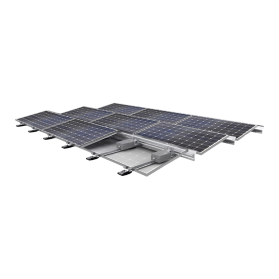
Page 10: System Overview
Clip for wind deflectors | CLP-WD Wind deflectors | S15WD-1800, S15WD-2050, S15WD-2300 Torx screw M8x16 A2-70 | AB8x16 Back support SN10 | SN10F Base rail | BR1355, BR2390 Starting piece base rail | BR130 Front support SN10 | SN10B www.aerocompact.com... -
Page 11: Roof Protection Pads
Different roof protection pads are supplied depending on the substrate. Roof protection pad PP 150/80 Roof protection pad PP 250/120-CL Roof protection pad PP 200/120-CL Ballasting Cross brace | CS1800, CS2050, CS2300 Ballast tray | BT-1800, BT-2050, BT-2300 Ballast terminal | CLB10 www.aerocompact.com... -
Page 12: Accessories
System overview Accessories Angle connection to mechanical attachment | AC200, AC80 Wire clamp for bonding | WCL8-10 Aluminium wire round 8 mm for bonding | AWR8 Cable tie clip to module | CLP-M www.aerocompact.com... -
Page 13: Assembly
Measure the width of the module field and mark the line. Determine the distance between the module rows according to the module manufacturer's instruc- tions + 2 cm distance between the modules. Measure the distance and mark the lines. www.aerocompact.com... -
Page 14: Preassemble The Front Supports
Make a gauge for dimension B. Module (A) 1000 1010 1020 1030 1040 1050 Distance (B) Module (A) 1060 1070 1080 1090 1100 1110 1120 1130 1140 1150 Distance (B) 1008 1017 1028 1038 1048 www.aerocompact.com... -
Page 15: Installing Roof Protection Pads
The roof protection pads are fitted as standard at the beginning and end of each base rail and in the area of the rear supports. Depending on the ballast, additional roof protection pads are installed per rail. Take the exact number and position of the roof protection pads from the AEROTOOL planning doc- uments. Positions PP 200/120-CL less ballast www.aerocompact.com... - Page 16 Place the roof protection pads so that the clip is facing upwards with the curvature. Install the roof protection pads underneath the base rail. Ensure that the tabs of the roof protection pad are completely enclosed by the profile. www.aerocompact.com...
-
Page 17: Version 2: Roof Protection Pad Pp 150/80
Pull off the protective backing from the roof protection pad. Place the roof protection pad underneath the base rail and adhere it in place. Ensure that the tabs of the roof protection pad are completely enclosed by the profile. www.aerocompact.com... -
Page 18: Place Rail Lines
Ballast in front of the back support (under the module) Attach the ballast clamp to the base rail. Place the ballast blocks on the base rail flush with the back support. Align the ballast clamp and place the ballast block www.aerocompact.com... -
Page 19: Variant 2: Cross Struts As Ballast Rail
Lay out the ballast rails so that they overlap at the supports. Hand tighten the ballast rails to the base rail. Tighten the screws to 10 Nm or 7.38 ft lb with a torque wrench. Lay out ballast blocks according to Aerotool planning documents. www.aerocompact.com... -
Page 20: Variant 3: Ballast Tray
Refer to the Aerotool planning documents for the exact number and position of the ballast trays. Align ballast trays To achieve a stronger compound, the ballast trays are each bolted to 3 base rails. Screw the outer ballast tray's center holes with the penultimate base rail If necessary, mount two ballast trays half overlapping. www.aerocompact.com... -
Page 21: Installing Modules
Tighten the screws to 10 Nm or 7.38 ft lb with a torque wrench. Lay out ballast blocks according to Aerotool plan- ning documents. Installing modules Attach the end clamps to all front supports. Start by installing the modules in the front row. www.aerocompact.com... - Page 22 The distance (A) between the modules is 2 cm. As an aid 2 clamps can be used as gauges. Attach an end clamp to the rear upright. Continue placing the modules row by row. Align the rail lines as required. www.aerocompact.com...
-
Page 23: Compound
Take the exact number and position of the angle profiles from the Aerotool planning documents. Screw the angle profiles flush to the back supports. Tighten the screws with 15 Nm or 11 ft lb each. Install microinverter (optional) The microinverter is installed directly on the module. www.aerocompact.com... -
Page 24: Install Wind Deflectors
Vor dem Montieren der Windleitbleche alle Verkabelungsarbeiten abschließen. To achieve a stronger compound, the wind deflectors are each bolted to 3 back supports. Attach the outer wind deflector's center holes at the penultimate back support If necessary, mount two wind deflectors half overlapping. www.aerocompact.com... -
Page 25: Installing The Roof Anchor
Mount the angle connection to the mechanical attachment on a rear support. Tighten the screws with 15 Nm or 11 ft lb. Bonding For bonding, AEROCOMPACT provides the bonding wire clamp and the aluminium wire as accessories. These are mounted on a base rail. www.aerocompact.com... -
Page 26: Maintenance
Complete System Check all components of the system for damage. Replace damaged components as soon as possible. Fittings Check all screw connections. Tighten loose screw connections. Confirm the tightening torque according to the assembly instructions. www.aerocompact.com... - Page 27 Disassembly DISASSEMBLY Disassemble components Disassembling the system: Carry out the assembly steps in reverse order. Dismantle clamps Completely unscrew the screw on the clamp. If clamps are re-installed: Make sure that the O-ring is not lost. www.aerocompact.com...
Need help?
Do you have a question about the CompactFLAT SN10 and is the answer not in the manual?
Questions and answers