
Related Manuals for dynarex 10408


Summary of Contents for dynarex 10408
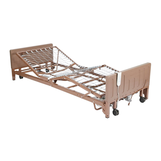
- Page 1 Reorder No. 10408 Manufactured for: Dynarex Corporation 10 Glenshaw Street Orangeburg, NY 10962 USA • www.dynarex.com Made in China Home Care Bed 3 Motor Full Electric...
-
Page 2: General Warnings
GENERAL WARNINGS Notices in this manual apply to hazards or unsafe OPERATIONAL CAUTIONS practices that could result in personal injury and/or Inspect all parts for shipping damage before property damage. assembly and use. To ensure user safety in operating this Home Do not use any part or component that has been Care Bed, all warnings, safety information, and damaged. - Page 3 GENERAL WARNINGS ELECTRICAL WARNING WEIGHT WARNING Ensure all cables and cords are routed in a way Total weight capacity is 450 lb. excluding additional weight from rails, mattress, and other accessories. that they will not become entangled, pinched, or trampled. Suggested patient weight capacity is 400 lb.
- Page 4 GENERAL WARNINGS ACCESSORY CAUTIONS OXYGEN WARNING Improper use of some bed accessories (patient Do not use near explosive gases. This may cause a fire hazard when used with oxygen administering restraints, side rails, trapeze devices, etc.) can cause patient injury or death. Consult a health equipment other than nasal or masked type.
-
Page 5: Product List
PRODUCT LIST The Home Care Bed will arrive in two boxes with the following contents: 1 Instruction Manual 1 Headboard 1 Head Spring Section 1 Drive Shaft 4 Casters (2-locking, 2-non-locking) 1 Foot Board 1 Foot Spring Section 1 Emergency Hand Crank Headboard Foot Board Head Spring... -
Page 6: Bed Assembly
BED ASSEMBLY CONNECTING THE TWO FRAMES Figure 1 Head section Foot section 90° angle Figure 2 Figure 3 1. Remove the bolts fastened to the sides of the 7. After head and foot springs are connected, foot spring section near the connecting end of slowly open the frame sections into a horizontal the frame. - Page 7 BED ASSEMBLY INSTALLING THE CASTERS 1. Insert the shaft of the caster into the caster socket of each bed leg. Ensure the stem is fully CAUTION: Ensure that the locking casters are inserted into the socket. installed diagonally from each other and are locked.
- Page 8 BED ASSEMBLY INSTALLING THE HEADBOARD 4. Insert a clevis pin through the hole between AND FOOT BOARD the two rivets to lock the platform and the head frame together. Secure the pin with an R-clip. CAUTION: Do not place your hand between Repeat the procedure on the other side.
- Page 9 INSTALLING THE HEAD MOTOR 1. Before installing, make sure the color-coded 3. Extend the head deck shaft so it connects to hand pendent and motor cables are plugged the head deck pivot bracket. Attach the shaft into the control box. to the bracket using the supplied clevis pin and locking pin.
- Page 10 INSTALLING THE CENTER DRIVE SHAFT 1. Connect the drive shaft assembly to the bed by 3. Release the spring-loaded shaft on the hi/low first attaching either side of the drive shaft to the motor and insert the shaft into the gear box on Hi/Low motor.
-
Page 11: Bed Operation
BED ASSEMBLY CONNECTING THE SPRING “FABRIC” 1. Lift the head spring section upward to give slack 2. Connect the spring “fabric” together with the links to the spring “fabric.” provided. 3. Hook together all the links to the spring “fabric.” BED OPERATION Hand Control Pendant Depress button “HEAD UP”... -
Page 12: Emergency Hand Crank
EMERGENCY HAND CRANK 1. To raise or lower the head or foot deck, insert NOTE: If the bed is too low to properly rotate the the hand crank into the head motor or the foot crank as instructed in Step 2, you may adjust the motor and turn to move the corresponding part. -
Page 13: Maintenance And Safety Checks
MAINTENANCE AND SAFETY CHECKS Safety checks are recommended between patient 4. Make sure all plugs are fully inserted and free placements. of damage. If damaged contact an authorized technician for repair. An annual safety check is recommended. MECHANICAL MAINTENANCE INSPECTION Cleaning and electric inspection may be performed by the user. -
Page 14: Maintenance Schedule
MAINTENANCE SCHEDULE Maintenance should be performed at least once every 3 months. This form may be copied and used as a procedural guide and facility documentation. Serial # _______________________... -
Page 15: Limited Lifetime Warranty
LIMITED LIFETIME WARRANTY Your Dynarex Bed is warrantied to be free of defects in • Products where the serial number has been removed or materials and workmanship for five (5) years on structural defaced steel, one (1) year on mechanical parts/components, from •... - Page 16 SYMBOL GLOSSARY For an explanatio n of symbol s used in Dynar ex packaging , visit dynare x.com/ symbols.ph p R210625...
Need help?
Do you have a question about the 10408 and is the answer not in the manual?
Questions and answers