Table of Contents
Advertisement
Quick Links
Advertisement
Table of Contents
Troubleshooting

Subscribe to Our Youtube Channel
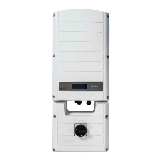
Related Manuals for SolarEdge 3000A-US


Summary of Contents for SolarEdge 3000A-US
-
Page 3: Disclaimers
The material furnished in this document is believed to be accurate and reliable. However, SolarEdge assumes no responsibility for the use of this material. SolarEdge reserves the right to make changes to the material at any time and without notice. You may refer to the SolarEdge web site (www.solaredge.com) for the most updated version. -
Page 4: Support And Contact Information
Serial number of the product in question The error indicated on the inverter screen or on the SolarEdge monitoring portal, if there is such an indication. System configuration information, including the type and number of modules connected and the number and length of strings. -
Page 5: Table Of Contents
Table of Contents ....................... 3 Handling and Safety Instructions ..................6 Safety Symbols ........................6 Instructions ........................7 Chapter 1: Introducing the SolarEdge System ..............8 System Overview .......................8 SolarEdge Power Optimizer ....................... 8 SolarEdge Inverter ........................8 SolarEdge AC/DC Safety Switch ....................8 SolarEdge Monitoring Portal ..................... - Page 6 Step 2, Pairing Power Optimizers to the Inverter ............29 Step 3, Verifying Proper Operation ..................30 Step 4, Reporting and Monitoring Installation Data ............30 The SolarEdge Monitoring System ..................30 Providing Installation Information ................... 31 Chapter 6: User Interface ....................32 Inverter LCD Panel and LEDs ....................32...
- Page 7 Appendix C: Mechanical Specifications ................63 AC/DC Safety Switch ......................63 Power Optimizers ......................65 Appendix D: Inverter Power De-rating ................66 Appendix E: Replacing and Adding System Components ........... 67 Replacing an Inverter .......................67 Adding, Removing or Replacing Power Optimizers............68 SolarEdge Installation Guide – MAN-01-00002-1.7...
-
Page 8: Handling And Safety Instructions
Ne pas dépasser une telle note avant que les conditions requises soient totallement comprises et accomplies. NOTE: Denotes additional information about the current subject. IMPORTANT SAFETY FEATURE: Denotes information about safety issues. SolarEdge Installation Guide – MAN-01-00002-1.7... -
Page 9: Instructions
Cet appareil doit être connecté uniquement à un circuit de dérivation dédié avec un coéfficient dispositif de protection contre les surintensités (TPOC) maximal de 40 A. NOTE: Use only copper conductors rated for a minimum of 90°C. SolarEdge Installation Guide – MAN-01-00002-1.7... -
Page 10: Chapter 1: Introducing The Solaredge System
SolarEdge Inverter The SolarEdge inverter efficiently converts DC power from the modules into AC power that can be fed into the main AC service of the site and from there to the grid. The inverter also receives the monitoring data from each power optimizer and transmits it to a central server (the SolarEdge monitoring server;... -
Page 11: Supported Ac Grids
Chapter 1: Introducing the SolarEdge System Supported AC Grids The following figure shows the AC grids supported by the SolarEdge inverter. Inverters framed with a border and that have their Neutral line connected can be set to Auto in setting the country and grid (refer to Country and Grid on page 37). -
Page 12: Installation Workflow
Chapter 1: Introducing the SolarEdge System Installation Workflow The following is the workflow for installing and setting up a new SolarEdge site. Most of these procedures can also be used for modifying an existing site. Page 12 Connecting power optimizers to modules and in a string... -
Page 13: Installation Equipment List
Chapter 1: Introducing the SolarEdge System Installation Equipment List Standard tools can be used during the installation of the SolarEdge system. The following is a recommendation of the equipment to be used: Allen screwdriver for 1/4" or 5/16" screw types ... -
Page 14: Chapter 2: Installing The Power Optimizers
Pour installation à même le module ou la monture du module, consultez d'abord le fabricant du module sur la position et son impact sur la garantie du module. SolarEdge Installation Guide – MAN-01-00002-1.7... -
Page 15: Package Contents
Installing a SolarEdge system without ensuring compatibility of the module connectors with the optimizer connectors may be unsafe and could cause functionality problems such as ground faults, resulting in inverter shut down. In order to ensure mechanical compatibility of the SolarEdge optimizers and the modules to which they are connected: ... -
Page 16: Step 1, Mounting And Grounding The Power Optimizers
The star washer should break through the anodize coating of the railing to ensure low-resistive connection. Apply torque of 9.5 N*m / 7 lb*ft. Figure 2: Power Optimizer Grounding Using the Star Washer SolarEdge Installation Guide – MAN-01-00002-1.7... -
Page 17: Step 2, Connecting A Module To A Power Optimizer
Verify that you have identified the inputs correctly. The power optimizer input cables are the short ones. Do not connect modules to power optimizer outputs. Vérifiez que vous avez identifié les entrées et sorties correctement. Ne pas connecter des modules aux sorties des optimiseurs de puissance. SolarEdge Installation Guide – MAN-01-00002-1.7... -
Page 18: Step 3, Connecting Power Optimizers In Strings
The minimum and maximum string lengths are specified in Appendix B: Technical Specifications on page 61. Refer to the SolarEdge Site Designer for string length verification. Connect the Minus (-) output connector of the string’s first power optimizer to the Plus (+) output connector of the string’s second power optimizer. -
Page 19: Troubleshooting
If a malfunctioning power optimizer is located, check its connections, polarity, module and voltage. If a malfunction cannot be bypassed or resolved, skip the malfunctioning power optimizer, thus connecting a shorter string. Do not continue before finding the problem and replacing the malfunctioning power optimizer. SolarEdge Installation Guide – MAN-01-00002-1.7... -
Page 20: Chapter 3: Installing The Inverter
Refer to the sticker on the inverter that specifies its Serial Number and its Electrical Ratings. Provide the serial number when contacting SolarEdge support. The serial number is also required when opening a new site in the SolarEdge monitoring portal. -
Page 21: Inverter Connectors
At least 15" (38 cm) to the bottom of the inverter, for the AC/DC Safety Switch; if conduit entry to the switch will be from the bottom, leave sufficient clearance for the conduits as well. 4" (10 cm) to the right and left of the inverter SolarEdge Installation Guide – MAN-01-00002-1.7... - Page 22 Open the inverter cover’s six Allen screws and carefully lift the cover towards you before lowering it. CAUTION: When removing the cover, make sure not to damage internal components. SolarEdge will not be held responsible for any components damaged as a result of incautious cover removal.
-
Page 23: Chapter 4: Installing The Ac/Dc Safety Switch
In DCD-1ph-US-B package - front cover of the AC/DC Safety Switch AC/DC Safety Switch mounting bracket Template for marking the bracket mounting holes on the mounting surface Four flat head screws for fastening the AC/DC Safety Switch to the bracket SolarEdge Installation Guide – MAN-01-00002-1.7... -
Page 24: Opening Conduit Knockouts
Drill the holes and connect the bracket. Verify that the bracket is firmly attached to the mounting surface. Unscrew the two nuts at the conduit ends. SolarEdge Installation Guide – MAN-01-00002-1.7... -
Page 25: Connecting The Switch To The Inverter
Tighten the screws of each terminal with a torque of 1.2-1.5 N*m / 0.88-1.1 lb*ft. Verify that there are no unconnected wires at the output of the AC/DC Safety Switch and that the unused terminal screws are tightened. SolarEdge Installation Guide – MAN-01-00002-1.7... -
Page 26: Connecting The Strings And The Ac To The Ac/Dc Safety Switch
AC Side Conduit DCD-1ph-US-B Safety Switch DC Connections AC Connections Equipment Grounding Terminal DC Side Conduit AC Side Conduit DCD-1ph-US-C Safety Switch DC Connections AC Connections Equipment Grounding Terminal Figure 17: Inside the AC/DC Safety Switch SolarEdge Installation Guide – MAN-01-00002-1.7... -
Page 27: Grid Connection Guidelines
When connecting multiple inverters in an installation connected to a three-phase grid, phase balancing may be required by the utility or grid operator. Phase balancing is supported in the SolarEdge inverters. For detailed information, refer to the SolarEdge Phase Balancing Manual, available on the SolarEdge website at http://www.solaredge.com/files/pdfs/phase_balancing_connection_guide.pdf. -
Page 28: Connecting The Strings To The Ac/Dc Switch
NEC690.35(B). NOTE: SolarEdge’s fixed input voltage architecture enables the parallel strings to be of different lengths. Therefore, they do not need to have the same number of power optimizers, as long as the length of each string is within the permitted range. -
Page 29: Closing The Ac/Dc Safety Switch And Inverter Covers
For proper sealing, first tighten the corner screws and then the two central screws. The recommended order can be seen in the following figure: Figure 23: Tightening Order of the Screws Proceed with Chapter 5: Commissioning the Installation on page 28. SolarEdge Installation Guide – MAN-01-00002-1.7... -
Page 30: Chapter 5: Commissioning The Installation
000, since no power optimizers have been paired. S_OK: the connection to the SolarEdge Monitoring server is successful (should appear only if the inverter is connected to the server). If S_OK is not displayed and the inverter is connected to the server, refer to Verifying the Connection on page51 for troubleshooting. -
Page 31: Step 2, Pairing Power Optimizers To The Inverter
When countdown is complete, the inverter enters Production mode and produces power. This mode is indicated by the steadily lit green inverter LED. SolarEdge Installation Guide – MAN-01-00002-1.7... -
Page 32: Step 3, Verifying Proper Operation
Pac [W] specifies the total AC output power produced. Take note of the serial # on the inverter label. This information is used in the SolarEdge monitoring portal to identify this inverter and is needed to open a new site in the monitoring portal. -
Page 33: Providing Installation Information
The logical and physical mapping can be used for debugging a problem using the SolarEdge monitoring portal. If you do not report the physical and logical mapping of the installed power optimizers to SolarEdge, the SolarEdge monitoring portal will show the logical layout indicating which power optimizers are connected to which inverters, but will not show strings or the physical location of power optimizers. -
Page 34: Chapter 6: User Interface
Fault - Red: Indicates that there is an error. Refer to Appendix A, Errors and Troubleshooting on page 53 for more information. In addition, this LED blinks while the inverter is being shut down. All LEDs are on while the inverter is being configured. SolarEdge Installation Guide – MAN-01-00002-1.7... -
Page 35: Lcd User Buttons
Error messages: In the event of a problem, an error message may be displayed on the LCD panel. Refer to Appendix A: Errors and Troubleshooting on page 53 and to Configuring the Inverter Using the LCD User Buttons on page 34 for more information. SolarEdge Installation Guide – MAN-01-00002-1.7... -
Page 36: Setup Mode
The inverter is now in Setup mode and all its LEDs are lit. The inverter automatically exits Setup mode if no buttons are pressed for more than 2 minutes. The following shows a hierarchical tree of the menu options, which are described in Inverter Configuration Menu Options on page 37: SolarEdge Installation Guide – MAN-01-00002-1.7... - Page 37 U p g r a d e C a r d Information: V e r s i o n s E r r o r L o g W a r n i n g l o g SolarEdge Installation Guide – MAN-01-00002-1.7...
-
Page 38: Configuring The Inverter Using The External Lcd Light Button
Short-press to scroll down to the next menu option, and long-press to select the item. You can use the Exit options in these menus to move up one menu level or to exit the Setup mode from the main menu. SolarEdge Installation Guide – MAN-01-00002-1.7... -
Page 39: Connecting A Laptop To The Inverter
The inverter must be configured to the proper country in order to ensure that it functions properly with that country’s grids. L'onduleur doit être configuré pour le pays approprié afin d'assurer un fonctionnement convenable avec le réseau de ce pays. SolarEdge Installation Guide – MAN-01-00002-1.7... - Page 40 Select Server to set which communication method is used to communicate between the inverter and the SolarEdge monitoring server. Refer to Chapter 7: Setting Up Communication on page 45 for a full description of these communication options.
- Page 41 P r o t o c o l < D R C T > S e t A P N S e t U s e r N a m e S e t P a s s w o r d SolarEdge Installation Guide – MAN-01-00002-1.7...
- Page 42 U p g r a d e C a r d Date and Time: Set the internal real-time clock. If connected to the SolarEdge monitoring portal, the date and time are set automatically and only time zone should be set. ...
-
Page 43: Operational Mode - Status Screens
If XXX and YYY are not equal there may be a pairing issue. S_OK: The connection to the SolarEdge Monitoring server is successful (should appear only if the inverter is connected to the server) ... -
Page 44: Main Inverter Status Window
D S P 1 / 2 : 1 . 0 2 1 0 / 1 . 0 0 3 4 C P U : 0 0 0 2 . 0 1 1 1 C o u n t r y : U S A 2 SolarEdge Installation Guide – MAN-01-00002-1.7... -
Page 45: Server Communication Status Window
I D : X X X X X X X X M I D : X X X X RSSI: The receive signal strength of the closest ZigBee in the SolarEdge system. L = low, M = medium, H = high and - = no signal. ... -
Page 46: Communication Ports Status Window
MPM: ZigBee multipoint master (for a ZigBee coordinator module) MPS: ZigBee multipoint slave (for a ZigBee router module) For a revenue meter reader, refer to the supported revenue meters page at http://www.solaredge.com/articles/se-supported-devices. For a non-SolarEdge logger: SS: SunSpec SolarEdge Installation Guide – MAN-01-00002-1.7... -
Page 47: Chapter 7: Setting Up Communication
The information is then sent from the inverter to the SolarEdge monitoring portal through the Internet. In order to send the data from the inverter, a communication connection must be set up, as described in this chapter. Communication setup is not required for power harvesting and is needed only for using the SolarEdge monitoring portal. -
Page 48: Creating An Ethernet (Lan) Connection
Remove the cable’s external insulation using the crimping tool or cable cutter and expose eight wires. CAT5/6 standard cables have eight wires (four twisted pairs), as shown in the diagram below. Wire colors may differ from one cable to the next. Figure 29: Standard Cable Wiring SolarEdge Installation Guide – MAN-01-00002-1.7... - Page 49 4 and 5 Blue + White/Blue Orange 7 and 8 Brown + White/Brown Aluminium shield G-unconnected Tighten the screws of the Ethernet terminal block. Push the Ethernet terminal block firmly all the way into the communication board. SolarEdge Installation Guide – MAN-01-00002-1.7...
-
Page 50: Creating An Rs485 Bus Connection
Each inverter sends its monitored data independently to the SolarEdge monitoring portal. All connections are initiated from the inverter so that no port forwarding is required. - Page 51 Connect all B, A and G pins in all inverters. The following figure shows this connection schema: Figure 36: Connecting the Inverters in a Chain NOTE: Do not cross-connect B, A and G wires. Do not insert wires into RS485-2 pins. SolarEdge Installation Guide – MAN-01-00002-1.7...
- Page 52 The inverter should report the correct number of slaves. If it does not, verify the connections and terminations. Verify the connection of the master to the SolarEdge monitoring server, as described in Verifying the Connection below. SolarEdge Installation Guide – MAN-01-00002-1.7...
-
Page 53: Creating A Zigbee Connection
Turn ON the AC to the inverter by turning on the circuit breakers on the main circuit board and turning on the inverter, and verify that the AC/DC Safety Switch is ON. Wait for the inverter to connect to the SolarEdge monitoring server. This may take up to two minutes. - Page 54 For WIFI networks, ensure that username and password are as defined in the internet provider AP/router. Server x Ping Ping to redundant server #x Check the SolarEdge server address, Failed failed as described on page 43. Tcp Connect. The connection to the SolarEdge...
-
Page 55: Appendix A: Errors And Troubleshooting
2 V is measured, then the fault is in this string. Do not connect strings with a grounding fault to the inverter. For further documentation about possible ground current error sources and solutions contact SolarEdge support. SolarEdge Installation Guide – MAN-01-00002-1.7... - Page 56 Re-commission all inverters in the site, as described in Chapter 5: Commissioning the Installation on page 28. Hardware Error Internal hardware error. If the fault persists, contact SolarEdge support. Temperature Too Over temperature. If the fault persists: High ...
- Page 57 Grid voltage is below Handle this in the same manner as error 32. the limit permitted. This error is checked only in the USA. Internal HW Error Internal hardware error. If the fault persists, contact SolarEdge support. SolarEdge Installation Guide – MAN-01-00002-1.7...
- Page 58 Selected configured to any country. 4, 5, 8, SW Error Internal software error. If the fault persists, contact SolarEdge support. 18-23, 39, 42, Change the Phase Balance option in the Inverter’s Phase Unbalance LCD menu to Disable. SolarEdge Installation Guide – MAN-01-00002-1.7...
-
Page 59: Appendix B: Technical Specifications
12.5 Output Current @240V Max. Continuous 18.5 Output Current @277V Max. Output Overcurrent Protection Power Factor GFDI Utility Monitoring, Islanding Protection, Country Configurable Thresholds SE3000A-US and SE7000A-US are available with Hawaii settings (Part number SExxxxA-US-HI) SolarEdge Installation Guide – MAN-01-00002-1.7... - Page 60 Supported RS485, RS232, Ethernet, ZigBee (optional) Communication Interfaces Standard Compliance Safety UL1741 Grid Connection Utility interactive, IEEE1547 Standards Emissions FCC part15 class B RoHS Higher input DC power may be installed; analyze yearly AC performance. SolarEdge Installation Guide – MAN-01-00002-1.7...
- Page 61 V > 120 % 0.16 Frequency Range (Hz) Max. Clearing Time (Sec) > 60.5 0.16 < 59.3 (Hawaii – 57) 0.16 Power de-rating over 120F/50C. Refer to Appendix D: Inverter Power De-rating on page 118 for details. SolarEdge Installation Guide – MAN-01-00002-1.7...
-
Page 62: Ac/Dc Safety Switch
35 A or 40 A AC/DC Safety Switch Specifications Maximum DC voltage Maximum DC current Nominal AC voltage 277/240/208 Maximum AC current Ambient temperature -40 to +65 °C Weight DCD-1ph-US-B: 6.5 / 3 lb/Kg DCD-1ph-US-C: 5.29 / 2.4 SolarEdge Installation Guide – MAN-01-00002-1.7... -
Page 63: Power Optimizers
(Controlled by Inverter) Output During Standby (power optimizer disconnected or inverter off) Safety Output Voltage per Power Optimizer PV System Design Using a SolarEdge Inverter Minimum Number of Power Optimizers per String (1 or More Modules per power optimizer) Maximum Number of Power Module power dependent;... - Page 64 -40 - +65 / -40 - +150 Protection Rating 2NA Series: IP65 / NEMA 4 IP65 / NEMA 4 3NA Series: IP67 / NEMA 6 Relative humidity 0 - 100 ** OP400-MV may be ordered with 3ft 11in output PV wire. SolarEdge Installation Guide – MAN-01-00002-1.7...
-
Page 65: Appendix C: Mechanical Specifications
Appendix C: Mechanical Specifications Appendix C: Mechanical Specifications AC/DC Safety Switch Figure 38: DCD-1ph-US-B Dimensions SolarEdge Installation Guide – MAN-01-00002-1.7... - Page 66 Appendix C: Mechanical Specifications 9.5in / 241mm 4.8in / 122mm 12.3in / 312mm 8.3in / 211mm 11.3in / 287mm Figure 39: DCD-1ph-US-C Dimensions SolarEdge Installation Guide – MAN-01-00002-1.7...
-
Page 67: Power Optimizers
Dimensions (mm/in) 143 x 210 x 45/ 137 x 193 x 27/ 5.63 x 8.26 x 1.75 5.39 x 7.62 x 1.06 (W x L x H) 2NA Series 3NA Series Figure 40: Power Optimizer Dimensions SolarEdge Installation Guide – MAN-01-00002-1.7... -
Page 68: Appendix D: Inverter Power De-Rating
Appendix D: Inverter Power De-rating Appendix D: Inverter Power De-rating SolarEdge’s 5kW, 6kW and 7kW inverters operate at full power and full currents up to a temperature of 120°F/50°C. The inverters may be used above this temperature with reduced ratings. The de-rating of these inverters, when connected to the 208V, 240V and 277V grids, is shown in the graph below. -
Page 69: Appendix E: Replacing And Adding System Components
Connect the DC and AC wires to the inverter and tighten the conduit nuts. Close the cover. Turn ON the AC switch of the main circuit board, the AC/DC Safety Switch and the inverter ON/OFF switch. SolarEdge Installation Guide – MAN-01-00002-1.7... -
Page 70: Adding, Removing Or Replacing Power Optimizers
28 on all inverters to which power optimizers were added or from which power optimizers were removed. In the monitoring portal, replace the serial number of the removed power optimizer with serial number of the newly installed power optimizer. SolarEdge Installation Guide – MAN-01-00002-1.7...
Need help?
Do you have a question about the 3000A-US and is the answer not in the manual?
Questions and answers