
Subscribe to Our Youtube Channel
Related Manuals for SolarEdge SE-DBL-US Series


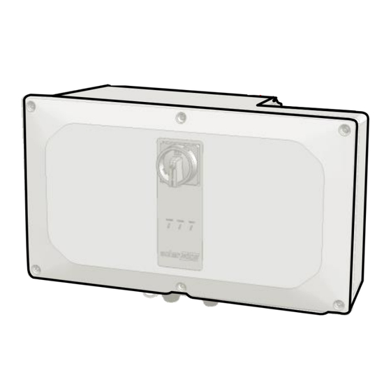
Summary of Contents for SolarEdge SE-DBL-US Series
- Page 1 Three Phase Inverter with Synergy Technology Quick Installation Guide PN: xSE-DBL-USxxlxxxx, xSE-TRI-USxxlxxxx For North America Version 1.0 Scan for full installation guide...
- Page 2 SAVE THESE INSTRUCTIONS – This manual contains important instructions for the Three Phase Inverter with Synergy Technology that should be followed during installation and maintenance. Using this equipment in a manner not specified in this guide by SolarEdge may impair the protection provided by this equipment.
- Page 3 Install the Power Optimizers SolarEdge Designer Download SolarEdge Mapper to map Power Optimizers to design the system Download MAN-01-01119-1.0...
- Page 4 Monitoring platform Star washers for the C-series optimizer are not included and can be purchased in large The Power Optimizer must be grounded. For details, see quantities. SolarEdge part numbers: OPT-Washer-100 or OPT-Washer-500. Grounding SolarEdge Power Optimizers – Application Note MAN-01-01119-1.0...
- Page 5 Install the Power Optimizers 1:1 Series connection Connect input from module. Extension wires (4mm 2 /12AWG) Connect output to optimizer between optimizers are allowed between string. rows and around obstacles. MAN-01-01119-1.0...
- Page 6 Connect the PV Array Check array polarity. V erify 0.5+/-0.075V per optimizer Example: 30 optimizers = ~15V MAN-01-01118-1.0...
- Page 7 Maintain Clearance 15cm / 6” Indoor Clearance 20cm / 8” where annual average high temperature equals or above 25˚C / 77˚F 40 cm / 16” 10cm / 4” Outdoor Clearance 5cm / 2” Horizontal Installation WARNING! Area in front of the inverter must be kept clear for at least 1m/ 3.3ft.
- Page 8 Mark and Drill Holes Level provided template horizontally 6.1” / 15.5cm 6.1” / 15.5cm Drill holes 3.3” / 9.3cm 3.3” / 9.3cm Mark holes Optional Optional Ø 9mm / 0.35” Avoid wobbly installation by adding back support. Position provided template vertically Optional unit - model dependent 7.36”...
- Page 9 Mount the Units 2.9 lbfft For left or right units, use only the outer screw. 2.9 lbfft 2.9 lbfft 2.9 lbfft 18KG/ 40lbfft 32KG/ 70lbfft MAN-01-01119-1.0...
- Page 10 Connect Cables Align pin grooves in the connector with pin guides in socket. Connect cables CAUTION! Do not according to labels. block airflow. Boundary for single conduit entry. Max conduit size 7.62cm/3”. Max conduit Max conduit size size CAUTION! Remove plates from 6.35cm/2.5”...
- Page 11 Remove Covers WARNING! DISCONNECT POWER BEFORE BEGINNING INSTALLATION P 1 0 OFF (0) MAN-01-01119-1.0...
- Page 12 Connect PV Strings (Multi–Input Synergy Manager) When using a stranded wire, use of ferrule is at the installer discretion. 6 - 12 AWG ” 18 mm Ground the conduit nut if required by regulation. Up to 9 Strings MAN-01-01119-1.0...
- Page 13 Connect PV Strings (Combined-Input Synergy Manager) Synergy Units Left Center Right Left Center Right Allen 3/16” 4 AWG: 3.7 lbfft 3 – 2 AWG: 5.9 lbfft 2.2 lbfft 4-14 AWG Ground conduit nut if required by regulation. Important! Use 90°C copper Ferrule When installing a system with more than 2 strings per or aluminum wire.
- Page 14 Connect AC and Protective Earth The inverter can either support 4 wire + PE or 3 wire + PE connection. Overcurrent protection for the AC output must be provided by others, see manual for guidance. Max 1.29” / 33 mm Ø...
- Page 15 Set up Communication COMM 1 4 lbfft Ethernet MAN-01-01119-1.0...
- Page 16 Establish RS485 Connection of Multiple Inverters Move SW1 switch to ON (up) to terminate first and last inverters on RS485 bus. COMM 2 3 lbfft RS485-1 CAT6, 3-wire, shielded, twisted pair (0.2- 1 mm²) max 1km / 3300 ft. MAN-01-01119-1.0...
- Page 17 Connect Wi-Fi Communication (Optional) 4 lbfft MAN-01-01119-1.0...
- Page 18 Connect Cellular Communication (Optional) 3 lbfft *The antenna is optional. MAN-01-01119-1.0...
- Page 19 Install Covers lbfft MAN-01-01119-1.0...
- Page 20 Pre-commission when AC Power is Not Connected (Option 1) Download SolarEdge Turn DC Disconnect Start and follow Connect power bank switch to ON SetApp SetApp Start Download Power bank: 60W output port , USB-C Power Delivery (PD): 20V 3A (not provided)
- Page 21 Commission with DC and AC Power (Option 2) Turn ON Download SolarEdge SetApp Scan inverter QR code (for RS485 bus scan leader inverter first) ON (1) P 1 0 MAN-01-01119-1.0...
- Page 22 (Option 2) Mark the selected model Set inverter model Start and follow SetApp on the inverter’s label SE50KUS SE100KUS SE110KUS SE120KUS After confirming the inverter model number in SetApp, only the SolarEdge support team can modify the inverter model MAN-01-01119-1.0...
- Page 23 Commission the Leader Inverter Commissioning Country & Language Pairing Site Communication Solaredge Leader RS485-1 Protocol SolarEdge Follower Detect RS485-1 Inverter Units Status MAN-01-01119-1.0...
- Page 24 View System Status POWER COMM FAULT Green Blue System is producing Power AC is connected but the system is not producing power Inverter is communicating with the monitoring platform System error MAN-01-01119-1.0...
- Page 25 Product Information and Support For the latest updates, see: Quick Installation Guide (online) Datasheet SolarEdge Customer Support MAN-01-01119-1.0...
- Page 26 Support Contact Information If you have technical problems concerning SolarEdge products, please contact us: https://www.solaredge.com/service/support Subject to change without notice. Copyright © SolarEdge Inc. All rights reserved. February 2022.
Need help?
Do you have a question about the SE-DBL-US Series and is the answer not in the manual?
Questions and answers