Advantech ICR-4401 User Manual
Lan industrial router
Hide thumbs
Also See for ICR-4401:
- User manual (46 pages) ,
- Hardware manual (44 pages) ,
- Start manual (9 pages)
Table of Contents
Advertisement
Quick Links
Advertisement
Table of Contents

Subscribe to Our Youtube Channel
Related Manuals for Advantech ICR-4401


Summary of Contents for Advantech ICR-4401
- Page 1 LAN Industrial Router ICR-4401 USER MANUAL...
- Page 2 ICR-4401 c 2022 Advantech Czech s.r.o. No part of this publication may be reproduced or transmitted in any form or by any means, electronic or mechanical, including photography, recording, or any information storage and retrieval system without written consent. Information in this manual is subject to change without notice, and does not represent a commitment on the part of Advantech.
- Page 3 Information, notice – Useful tips or information of special interest. GPL licence Source codes under GPL licence are available at https://icr.advantech.cz/source-code address. Advantech Czech s.r.o., Sokolska 71, 562 04 Usti nad Orlici, Czech Republic Document No. MAN-0064-EN, revision from March 3, 2022. Released in the Czech Republic.
-
Page 4: Table Of Contents
ICR-4401 Contents 1 Product Oveview 1.1 Product Introduction ....... . . - Page 5 ICR-4401 Appendix B: Customer Support Appendix C: Regulatory & Safety Information Appendix D: Related Documents...
- Page 6 ICR-4401 List of Figures Access to the Internet from LAN ......Backed up Access to the Internet .
- Page 7 ICR-4401 List of Tables Hardware Overview of the Router ......Order Codes Overview ....... .
-
Page 8: Product Oveview
ICR-4401 1. Product Oveview 1.1 Product Introduction The ICR-4401 is a LAN Router & Powerful Edge Computing Gateway focused on the global market. This router is an ideal solution for demanding IoT applications such as industrial routers and gateways, digital signage, industrial computers, and tablets, etc. -
Page 9: Product Usage Examples
ICR-4401 1.2 Product Usage Examples The router is primarily intended for these four basic situations: I. Access to the Internet from LAN Figure 1: Access to the Internet from LAN II. Backed up access to the Internet (from LAN) Figure 2: Backed up Access to the Internet... -
Page 10: Using Vpn Tunnel
ICR-4401 III. Secure networks interconnection or using VPN Figure 3: Using VPN Tunnel IV. Serial Gateway Figure 4: Serial Gateway... -
Page 11: Hardware Overview
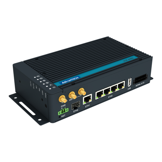
ICR-4401 1.3 Hardware Overview The router case preview is shown in Figure 5. A short description of hardware parts of the router is listed in Table 1, including the links to the chapters with a detailed description. Figure 5: Hardware Overview of the Router... -
Page 12: Hardware Overview Of The Router
ICR-4401 Item/Caption Type Description LEDs Status LED indication; see Chapter 2.9. Button to reboot the router or to restore the default configuration; see Chapter 2.10. 2-pin Power supply socket; see Chapter 2.4. terminal ETH2 SFP cage SFP cage socket for modules with speed up to 10 Gbps;... -
Page 13: Order Codes
ICR-4401 1.4 Order Codes Order codes overview is shown in the table below. Order code Configuration ICR-4401 Gb ETH SWITCH, GNSS, SFP cage, USB, microSD card slot, RS232, RS485, CAN bus, two binary inputs, two binary outputs ICR-4401S Gb ETH SWITCH, GNSS, SFP cage, PoE PSE, USB, microSD card slot,... -
Page 14: Package Contents
ICR-4401 1.5 Package Contents The standard set of router includes items listed in the following table: Item# Description Figure Q’ty 1 pcs Router Wing for wall mounting 2 pcs (screwed on the router) 2-pin terminal block for power supply 1 pcs... -
Page 15: Product Dimensions
ICR-4401 1.6 Product Dimensions For the dimensions of the router see the figures below. Note that all sizes are measured in millimeters. Figure 5: Router Dimensions – Front View Figure 6: Router Dimensions – Top View... -
Page 16: Mounting Recommendations
ICR-4401 1.7 Mounting Recommendations The router can be placed: on a flat surface, on a wall using the wall mounting clip (see Chapter 1.8), on a DIN rail EN 60715 with the metal DIN rail clip (see Chapter 1.9) For most applications with a built-in router within a switchboard, it is possible to recognize... -
Page 17: Wall Mounting
ICR-4401 1.8 Wall Mounting The wall mounting clip is supplied with the router as standard accessories. The router can be screwed to a wall (or another surface) using the wall mounting clips. Two wall mounting clips are assembled to the router during the production and need to be roteted as shown of Figure 7. -
Page 18: Din Rail Mounting
ICR-4401 1.9 DIN Rail Mounting The DIN rail clips are not supplied with the router as standard accessories, but they can be ordered by the order code BB-DIN-ICR32 (two pieces for one router). Two DIN rail clips can be assembled to the router and used to mount it to the DIN rail which meets the 60715 standards. -
Page 19: Product Label
ICR-4401 1.10 Product Label An example of the product label, with all the information printed on it, is in the figure below. Figure 10: Label Example... -
Page 20: Hardware Functionality
ICR-4401 2. Hardware Functionality See Chapter for the product hardware overwiew. Table lists a short description of the hardware, including the links to the chapters with a detailed description. 2.1 Antennas Interfaces Three R-SMA connectors WIFI1 are designed for the connection of the WiFi antennas. -
Page 21: Sfp Cage
ICR-4401 2.3 SFP Cage A hot-pluggable (SFP) network interface module with a speed of up to 10 Gbps can be settled into the ETH2 SFP cage. Installing an SFP Module To install a SFP module, see Figure and follow these steps: You should use the bale clasp if the SFP module is equipped with it. -
Page 22: Power Supply
ICR-4401 2.4 Power Supply Two pin terminal connector with 3.5 mm pitch is used to power the router. Corresponding connector is supplied with the router as a standard accessories. Signal mark Description VCC(+) Positive pole of DC supply voltage (+9 to +48 V DC) -
Page 23: Position Of The Grounding Screw
ICR-4401 All metal parts, including the box, are connected together with the negative pole of the power supply (common pole). If recommended for the installation environment, protect the router by grounding it properly by the grounding screw on the right panel, see Figure 8. -
Page 24: I/O Port Interfaces
ICR-4401 2.5 I/O Port Interfaces The I/O user interface is designed for binary input processing and binary output control. The pinout of the I/O interface is described in Figure and Table 5. For detailed electrical parameters see Chapter 4.5. The functional scheme of connection for the binary input and binary output is in Figure 10. -
Page 25: Serial Interfaces
ICR-4401 2.6 Serial Interfaces The RS232, RS485 CAN serial interfaces together with the two I/O interfaces are physically connected to the 14-pin terminal block panel socket. All these interfaces are not isolated from the router. The pinout of this connector is described in Figure and the tables below. -
Page 26: Usb Port
ICR-4401 2.7 USB Port There is one USB 2.0 host port with socket of USB-A type. USB Mass Storages and FTDI serial converters are supported. For a piece of advice, how to fix an unsupported FTDI chip, see the Commands and Scripts application note, chapter How to Use Unsupported FTDI Chip. -
Page 27: Microsd Card Reader
ICR-4401 2.8 MicroSD Card Reader The microSD card reader is located on the router’s rear panel under a metal cover. This card reader allows the router to operate with microSD memory cards. The technical speci- fications are stated in the table below. The microSD card changing procedure is described below. - Page 28 ICR-4401 Mounting microSD Card to the System It is necessary to mount the microSD card to be able to access it in the system of the router. Follow these steps to mount the card: Use the dmesg command to see the list of recently connected devices.
-
Page 29: Led Status Indication
ICR-4401 2.9 LED Status Indication There are six LED indicators on the top side of the router to provide router status informa- tion. Moreover, ETH0 and ETH1 connectors, located on the front panel, have two additional LEDs providing information about the port status. -
Page 30: Reset Functions
ICR-4401 2.10 Reset Functions The RST button on the front panel can be used in three different situations: Reboot the router: Hold the RST button for less than 4 seconds, the router will be restarted. Factory reset – restore the default configuration: Hold the RST button for more than 4 seconds. -
Page 31: Overview Of Router Reboot And Reset
ICR-4401 Action Router behavior Trigger events – options Reboot Turns off and then Disconnect and reconnect the power. turns on the router Press the Reboot menu item in the web interface. Press the RST button and hold il less than 4 sec- onds. -
Page 32: First Use
ICR-4401 3. First Use 3.1 Connecting the Router Before putting the router into an operation, it is necessary to connect all the components that are required to run your applications, see Figure 15. Figure 15: Router Connection 3.2 Starting up the Router The router will start up when a power supply is connected to it. - Page 33 ICR-4401 his password. If logged in successfully, the user will have access to the router web interface, see Figure 16. See the configuration manual of the router for a detailed description and examples of the router configuration. After logging on to the device for the first time, we strongly recommend changing the default password due to security reasons.
-
Page 34: Router's Web Interface
ICR-4401 Figure 16: Router’s Web Interface A detailed description of the router settings in the web interface can be found in the configura- tion manual of the router. -
Page 35: Technical Parameters
ICR-4401 4. Technical Parameters 4.1 Basic Parameters Router parameters Temperature range Operating -40 C to +75 C Storage -40 C to +85 C Humidity Operating 5 to 95 % relative humidity non condensing Storage 5 to 95 % relative humidity non condensing... -
Page 36: Standards And Regulations
ICR-4401 4.2 Standards and Regulations Standards and regulations Radio EN 301 893, EN 300 328 EN 301 489-1, EN 301 489-17, EN 61000-4-2, EN 61000-4-3, EN 61000-4-4, EN 61000-4-5, EN 61000-4-6, EN 61000-6-2, EN 55032 Safety EN 62368-1, IEEE 802.3... -
Page 37: Type Tests And Environmental Conditions
ICR-4401 4.3 Type Tests and Environmental Conditions Phenomena Test Description Test levels EN 61000-4-2 Enclosure contact 6 kV (crit. A) RF field AM EN 61000-4-3 Enclosure 20 V/m (crit. A) modulated (80 – 1000 MHz) 10 V/m (crit. A) (1 – 6 GHz) -
Page 38: Parameters Of Wifi
ICR-4401 4.4 Parameters of WiFi WiFi Short Module Description Dual Band 2.4/5GHz 3x3 WiFi 5 (802.11ac Wave 1) Supported Standards IEEE: 802.11ac compliant & compatible with 802.11a/b/g/n Data Rate Up to 600 Mbps @ 2.4 GHz (3x3 MIMO OFDM) Up to 1300 Mbps @ 5 GHz Frequency Ranges 2.412 –... -
Page 39: Parameters Of I/O Ports
ICR-4401 4.5 Parameters of I/O Ports Electrical characteristics of the binary inputs are in Table 17. Status of the binary input can be retrieved in the router’s web interface (on the General Status page) or by the status ports and io get commands, see Commands and Scripts application note. -
Page 40: System Configuration
ICR-4401 4.7 System Configuration The main parametes of the system are listed in Table 19. Other technical parameters CPU architecture Quad-Core ARMv8-A (core Cortex-A72) CPU frequency 1200 MHz CPU power 4.72 DMIPS/MHz Flash memory 4 MB of NOR 4 096 MB of eMMC... -
Page 41: Appendix A: Troubleshooting
ICR-4401 Appendix A: Troubleshooting If you cannot connect to the router from your PC, your network card may be configured in such a way that it is not possible to connect to the router. Take one or more of the following steps in order to solve the problem: Make sure your PC’s network card is configured to obtain the IP address form the... - Page 42 ICR-4401 L2TP or IPSec isn’t establishing. Check the "System Log" page for error messages. IPSec tunnel establishes but the communication does not run. Probably there are bad routing rules defined in the connected devices, or the default gateway. Serial communication is not working.
- Page 43 ICR-4401 Appendix B: Customer Support Customer Support for Europe Advantech Czech s.r.o. Sokolska 71 562 04, Usti nad Orlici, Czech Republic Phone: +353 91 792444 Fax: +353 91 792445 E-mail: iiotcustomerservice@advantech.eu Web: www.advantech.com Customer Support for NAM Advantech B+B SmartWorx...
- Page 44 ICR-4401 Appendix C: Regulatory & Safety Information Safety Notices Please, observe the following instructions: The router must be used in compliance with all applicable international and national laws and in compliance with any special restrictions regulating the utilization of the router in prescribed applications and environments.
- Page 45 ICR-4401 Product Disposal Instructions The WEEE (Waste Electrical and Electronic Equipment: 2012/19/EU) directive was in- troduced to ensure that electrical/electronic products are recycled using the best available recovery techniques to minimize the impact on the environment. This product contains high quality materials and components which can be recycled.
- Page 46 ICR-4401 Appendix D: Related Documents Quick Start Guide for v4 Platform Configuration Manual for v4 Platform [EP] Product-related documents and applications can be obtained on Engineering Portal at address. https://icr.advantech.cz/download...
- Page 47 ICR-4401 We, Advantech Czech s.r.o., declare that the radio equipment narrated in this user’s manual complies with Radio Equipment Regulations 2017 (S.I. 2017 1206) (WiFi version) and with the Electromagnetic Compatibility Regu- lations 2016 (S.I. 2016 No. 1091 and S.I. 2016 No.
Need help?
Do you have a question about the ICR-4401 and is the answer not in the manual?
Questions and answers