
Related Manuals for Yamaha WR450F 2014


Summary of Contents for Yamaha WR450F 2014
- Page 1 Read this manual carefully before operating this vehicle. OWNER’S MANUAL WR450F 1DX-28199-E3...
- Page 2 EAU46091 Read this manual carefully before operating this vehicle. This manual should stay with this vehicle if it is sold.
- Page 3 Welcome to the Yamaha world of motorcycling! As the owner of the WR450F, you are benefiting from Yamaha’s vast experience and newest technology regarding the de- sign and manufacture of high-quality products, which have earned Yamaha a reputation for dependability.
- Page 4 IMPORTANT MANUAL INFORMATION EAU10134 Particularly important information is distinguished in this manual by the following notations: This is the safety alert symbol. It is used to alert you to potential personal injury hazards. Obey all safety messages that follow this symbol to avoid possible injury or death.
- Page 5 IMPORTANT MANUAL INFORMATION EAU10201 WR450F OWNER’S MANUAL ©2014 by Yamaha Motor Co., Ltd. 1st edition, February 2014 All rights reserved. Any reprinting or unauthorized use without the written permission of Yamaha Motor Co., Ltd. is expressly prohibited. Printed in Japan.
-
Page 6: Table Of Contents
TABLE OF CONTENTS SAFETY INFORMATION ....1-1 FOR YOUR SAFETY – Valve clearance ......6-18 PRE-OPERATION CHECKS ..... 4-1 Tires..........6-18 DESCRIPTION ........2-1 Spoke wheels ........ 6-20 Left view .......... 2-1 OPERATION AND IMPORTANT Adjusting the clutch lever free Right view ........ - Page 7 TABLE OF CONTENTS Replacing the fuse......6-32 Replacing the headlight bulb ..6-33 Tail/brake light ....... 6-34 Replacing a turn signal light bulb ..........6-35 Replacing the license plate light bulb ..........6-35 Replacing the auxiliary light bulb ........... 6-36 Supporting the motorcycle.....
-
Page 8: Safety Information
SAFETY INFORMATION EAU53005 Take a training course. Beginners replaced with non-specified com- should receive training from a cer- ponents, the vehicle will no longer tified instructor. Contact an autho- meet the regulations. Be a Responsible Owner rized motorcycle dealer to find out Watch carefully for other vehicles As the vehicle’s owner, you are respon- about the training courses nearest... - Page 9 SAFETY INFORMATION motorist’s blind spot. • Always obey the speed limit and could contribute to an impairment • Never maintain a motorcycle never travel faster than warrant- of vision that could delay seeing a without proper knowledge. Con- ed by road and traffic conditions. hazard.
- Page 10 Yamaha accessories, which are avail- When loading within this weight limit, ports. able only from a Yamaha dealer, have keep the following in mind: Do not run engine outdoors where been designed, tested, and approved ...
- Page 11 SAFETY INFORMATION mended by Yamaha, even if sold and sion travel, steering travel or con- electric failure could result, which installed by a Yamaha dealer. trol operation, or obscure lights or could cause a dangerous loss of reflectors. lights or engine power.
- Page 12 SAFETY INFORMATION tie-downs or suitable straps that are attached to solid parts of the motorcycle, such as the frame or upper front fork triple clamp (and not, for example, to rubber-mount- ed handlebars or turn signals, or parts that could break). Choose the location for the straps carefully so the straps will not rub against painted surfaces during transport.
-
Page 13: Description
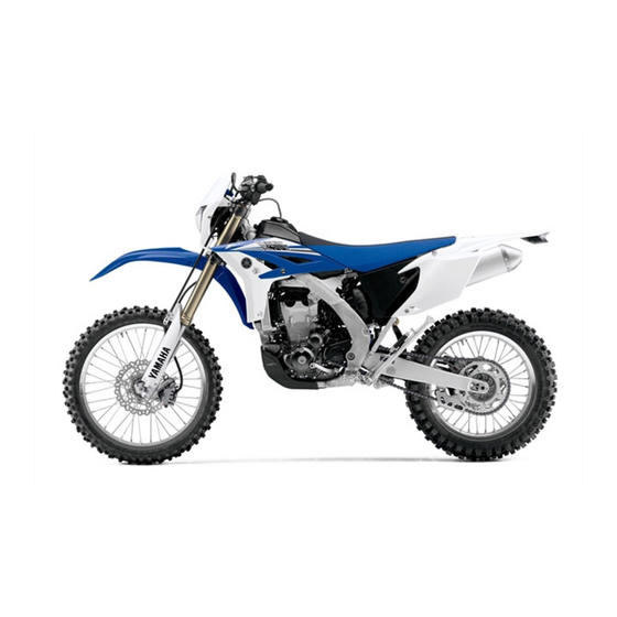
DESCRIPTION EAU10411 Left view 4, 5 6 1, 2 1. Front fork compression damping force adjusting screw (page 3-14) 9. Engine oil filler cap (page 6-8) 2. Bleed screw (page 3-15) 10.Engine oil drain bolt (oil tank) (page 6-8) 3. Starter knob/idle adjusting screw (page 3-12/6-17) 11.Engine oil tank cap (page 6-8) 4. -
Page 14: Right View
DESCRIPTION EAU10421 Right view 1, 2 1. Shock absorber assembly compression damping force adjusting 7. Coolant drain bolt (page 6-13) screw (for slow compression damping) (page 3-16) 8. Brake pedal (page 3-9) 2. Shock absorber assembly compression damping force adjusting nut 9. -
Page 15: Controls And Instruments
DESCRIPTION EAU10431 Controls and instruments 1. Clutch lever (page 3-8) 2. Left handlebar switches (page 3-7) 3. Multi-function display (page 3-2) 4. Main switch (page 3-1) 5. Front brake fluid reservoir (page 6-24) 6. Right handlebar switches (page 3-7) 7. Brake lever (page 3-8) 8. -
Page 16: Instrument And Control Functions
INSTRUMENT AND CONTROL FUNCTIONS EAU10452 EAU52472 EAU49396 Main switch Indicator lights and warning All electrical systems are off. lights EWA16131 WARNING Never push the main switch to “OFF” while the vehicle is moving, otherwise the electrical systems will be switched off, which may result in loss of control or an accident. -
Page 17: Multi-Function Display
“ON”, or if the warning light remains This warning light comes on when the operator and increase the risk of an on, have a Yamaha dealer check the fuel level drops below approximately accident. electrical circuit. - Page 18 INSTRUMENT AND CONTROL FUNCTIONS last set to zero) ton until the display changes after a clock the main switch is pushed to “ON”. Measurement mode: Basic mode a speedometer a distance-compensation tripme- Odometer and tripmeter modes ter (which shows the accumulated Push the “SLCT 2”...
- Page 19 INSTRUMENT AND CONTROL FUNCTIONS push either select button to set the Changing from the basic mode to hours. the measurement mode 3. Push the “RST” button, and the With the odometer selected, push the minute digits will start flashing. “SLCT 1” button and “SLCT 2” button 4.
- Page 20 INSTRUMENT AND CONTROL FUNCTIONS Auto start 1. Push the “SLCT 1” button for at Starting measurement consists of the least two seconds to set the auto following two starts, either of which can start. be selected. Manual start Starting measurement by the rider When the stopwatch is set to auto start, himself operating the button.
- Page 21 Resetting the distance-compensation specified. For further information con- tripmeter cerning the use of this meter, please 1. Check that the stopwatch mea- consult your nearby Yamaha dealer. surement is in operation. Calibrate the distance-compensation 2. Reset the distance-compensation tripmeter as follows.
-
Page 22: Handlebar Switches
INSTRUMENT AND CONTROL FUNCTIONS EAU1234H EAU12401 with the starter. See page 5-1 for start- Handlebar switches Dimmer switch “ ” ing instructions prior to starting the en- Set this switch to “ ” for the high gine. Left beam and to “ ”... -
Page 23: Clutch Lever
INSTRUMENT AND CONTROL FUNCTIONS EAU12821 EAU12872 EAU41265 Clutch lever Shift pedal Brake lever The brake lever is located on the right side of the handlebar. To apply the front brake, pull the lever toward the throttle grip. 1. Clutch lever 1. -
Page 24: Brake Pedal
INSTRUMENT AND CONTROL FUNCTIONS 3. While holding the lever pushed EAU12943 EAU13183 Brake pedal Fuel tank cap away from the throttle grip, turn the adjusting bolt in direction (a) to in- crease the distance, and in direc- tion (b) to decrease it. Distance between the brake lever and the throttle grip: Minimum (shortest):... -
Page 25: Fuel
Gasoline is poisonous and can Your Yamaha engine has been de- heat from the engine or the sun cause injury or death. Handle gaso- signed to use premium unleaded gaso- can cause fuel to spill out of the line with care. -
Page 26: Fuel Tank Breather Hose
INSTRUMENT AND CONTROL FUNCTIONS spark plug life and reduce maintenance EAU41362 EAU13434 Fuel tank breather hose Catalytic converter costs. This model is equipped with a catalytic converter in the exhaust system. EWA10863 WARNING The exhaust system is hot after op- eration. -
Page 27: Starter Knob
INSTRUMENT AND CONTROL FUNCTIONS pairable damage to the catalytic EAU53231 EAU13651 Starter knob Kickstarter converter. 1. Starter knob/idle adjusting screw 1. Kickstarter lever Starting a cold engine requires a richer To start the engine, fold out the kick- air-fuel mixture, which is supplied by starter lever, move it down lightly with the starter. -
Page 28: Steering Lock
INSTRUMENT AND CONTROL FUNCTIONS EAU53101 rection. EAU53201 Steering lock Seat 3. Remove the key. WARNING! Never ride with the key inserted To remove the seat into the steering lock, which Remove the bolts, and then slide the may result in loss of control and seat to the rear and pull upward. -
Page 29: Adjusting The Front Fork
INSTRUMENT AND CONTROL FUNCTIONS To install the seat EAU52451 Adjusting the front fork 1. Fit the slot in the seat onto the pro- EWA10181 jection on the fuel tank. WARNING Always adjust both fork legs equal- ly, otherwise poor handling and loss of stability may result. -
Page 30: Front Fork Bleeding
INSTRUMENT AND CONTROL FUNCTIONS each fork leg in direction (b). range. To obtain a precise adjustment, EAU14794 Front fork bleeding it would be advisable to check the num- EWA10201 ber of clicks of each damping force ad- WARNING justing mechanism and to modify the Always bleed both fork legs, other- specifications as necessary. -
Page 31: Adjusting The Shock Absorber Assembly
Maximum (hard): Spring preload Distance A = 222 mm (8.74 in) Spring preload adjustment should be made by a Yamaha dealer, since this Rebound damping force service requires special tools and tech- To increase the rebound damping force nical skills. The specified settings are and thereby harden the rebound damp- listed below. - Page 32 INSTRUMENT AND CONTROL FUNCTIONS sion damping force and thereby soften sion damping, turn the adjusting screw the compression damping, turn the ad- in direction (a). To decrease the com- justing bolt in direction (b). pression damping force and thereby soften the compression damping, turn the adjusting screw in direction (b).
-
Page 33: Sidestand
INSTRUMENT AND CONTROL FUNCTIONS visable to check the actual total number absorber assembly to a Yamaha EAU15306 Sidestand of clicks or turns of each damping force dealer for any service. The sidestand is located on the left side adjusting mechanism. This adjustment of the frame. -
Page 34: Ignition Circuit Cut-Off System
INSTRUMENT AND CONTROL FUNCTIONS Yamaha dealer repair it if it does not EAU52862 Ignition circuit cut-off system function properly. The ignition circuit cut-off system (com- prising the sidestand switch, clutch switch and neutral switch) has the fol- lowing functions. ... - Page 35 INSTRUMENT AND CONTROL FUNCTIONS WARNING With the engine turned off: 1. Move the sidestand down. If a malfunction is noted, have a Yamaha 2. Make sure that the engine stop switch is set to “ ”. dealer check the system before riding.
-
Page 36: For Your Safety - Pre-Operation Checks
• If necessary, add recommended coolant to specified level. 6-13 • Check cooling system for leakage. • Check operation. • If soft or spongy, have Yamaha dealer bleed hydraulic system. • Check brake pads for wear. Front brake • Replace if necessary. - Page 37 • Make sure that operation is smooth. • Check throttle grip free play. Throttle grip 6-18, 6-28 • If necessary, have Yamaha dealer adjust throttle grip free play and lubricate cable and grip housing. • Make sure that operation is smooth. Control cables 6-27 •...
- Page 38 • Tighten if necessary. Instruments, lights, signals • Check operation. — and switches • Correct if necessary. • Check operation of ignition circuit cut-off system. Sidestand switch 3-18 • If system is not working correctly, have Yamaha dealer check vehicle.
-
Page 39: Operation And Important Riding Points
For maximum engine life, never ac- a lean angle sensor to stop the en- understand, ask your Yamaha dealer. celerate hard when the engine is gine in case of a turnover. In this EWA10272... - Page 40 Use the kickstarter when the ambient light should come on. If not, ask a temperature is below 10 C (50 F) or Yamaha dealer to check the elec- when at high altitude. trical circuit. 2. With the throttle fully closed, push 3.
-
Page 41: Starting A Warm Engine
OPERATION AND IMPORTANT RIDING POINTS EAU52972 EAU16672 Starting a warm engine Shifting If the engine fails to start, push the main Follow the same procedure as for start- switch to “OFF” and give the kickstarter ing a cold engine with the exception 10 to 20 slow kicks at full throttle in or- that the starter is not required when the der to clear the engine of the rich air-fu-... -
Page 42: Tips For Reducing Fuel Consumption
Inade- vice, have a Yamaha dealer perform speeds with no load on the engine. quate lubrication may damage service. -
Page 43: Parking
10 to 15 more minutes. period, immediately have a ed. (See page 3-13 for more informa- The motorcycle will now be ready Yamaha dealer check the vehi- tion.) to ride normally. cle. EWA10312... -
Page 44: Periodic Maintenance And Adjustment
– possibly leading to pending on the weather, terrain, geo- that is certified (if applicable). Yamaha death. See page 1-2 for more in- graphical location, and individual use, dealers are trained and equipped to... -
Page 45: Owner's Tool Kit
If you do not have the tools or experi- ence required for a particular job, have a Yamaha dealer perform it for you. -
Page 46: Periodic Maintenance Chart For The Emission Control System
From 7000 km (4200 mi) or 9 months, repeat the maintenance intervals starting from 3000 km (1800 mi) or 3 months. Items marked with an asterisk should be performed by a Yamaha dealer as they require special tools, data and technical skills. -
Page 47: General Maintenance And Lubrication Chart
PERIODIC MAINTENANCE AND ADJUSTMENT EAU52582 General maintenance and lubrication chart ODOMETER INITIAL READINGS ANNUAL ITEM CHECKS AND MAINTENANCE JOBS 1000 km 3000 km 5000 km CHECK (600 mi) or (1800 mi) or (3000 mi) or 1 month 3 months 6 months •... - Page 48 PERIODIC MAINTENANCE AND ADJUSTMENT ODOMETER INITIAL READINGS ANNUAL ITEM CHECKS AND MAINTENANCE JOBS 1000 km 3000 km 5000 km CHECK (600 mi) or (1800 mi) or (3000 mi) or 1 month 3 months 6 months • Make sure that all nuts, bolts and screws are properly ...
- Page 49 PERIODIC MAINTENANCE AND ADJUSTMENT ODOMETER INITIAL READINGS ANNUAL ITEM CHECKS AND MAINTENANCE JOBS 1000 km 3000 km 5000 km CHECK (600 mi) or (1800 mi) or (3000 mi) or 1 month 3 months 6 months Moving parts and ...
-
Page 50: Removing And Installing The Panel
Do not attempt to diagnose 1. Panel A such problems yourself. Instead, have EAU52873 a Yamaha dealer check the vehicle. If the spark plug shows signs of elec- trode erosion and excessive carbon or Panel A other deposits, it should be replaced. -
Page 51: Engine Oil And Oil Filter Element
PERIODIC MAINTENANCE AND ADJUSTMENT wire thickness gauge and, if necessary, past finger tight. However, the spark EAU52967 Engine oil and oil filter adjusted to specification. plug should be tightened to the speci- element fied torque as soon as possible. The engine oil level should be checked before each ride. - Page 52 PERIODIC MAINTENANCE AND ADJUSTMENT And do not touch the radiator pipe after high-speed operation, otherwise the cooling system is hot and cause burns. Always let the engine oil cool down suffi- ciently before removing the oil tank cap. NOTICE: Do not [EWA16141] operate the vehicle until you know that the engine oil level is...
- Page 53 PERIODIC MAINTENANCE AND ADJUSTMENT engine oil filler cap. from the oil tank and crankcase. 8. Install the engine oil check bolt and gasket, and then tighten the bolt to the specified torque. Tightening torque: Engine oil check bolt: 10 Nm (1.0 m·kgf, 7.2 ft·lbf) 9.
- Page 54 PERIODIC MAINTENANCE AND ADJUSTMENT ment. installing the bolts, and then tight- en the bolts to the specified torque. Tightening torque: Oil filter element cover bolt: 10 Nm (1.0 m·kgf, 7.2 ft·lbf) Make sure that the O-rings are properly seated. 1. Oil filter element cover 11.
- Page 55 If this occurs, Make sure that no foreign mate- have a Yamaha dealer repair the rial enters the crankcase. vehicle. 13. Start the engine, and then let it idle...
-
Page 56: Coolant
The coolant should be at the bottom of sion. If water has been added to the radiator filler neck. The level will the coolant, have a Yamaha The coolant level must be checked change with variation of engine temper- dealer check the antifreeze con- on a cold engine since the level ature. -
Page 57: Cleaning The Air Filter Element And Check Hose
9. Start the engine, and then check 5. Install the coolant drain bolt and its the vehicle for coolant leakage. If new gasket, and then tighten the coolant is leaking, have a Yamaha bolt to the specified torque. dealer check the cooling system. Tightening torque: Coolant drain bolt: 10 Nm (1.0 m·kgf, 7.2 ft·lbf) - Page 58 The sponge material should be wet but not dripping. Recommended oil: Yamaha foam air filter oil or other quality foam air filter oil 1. Air filter element frame 2. Sponge material 5. Pull the sponge material over the air filter element frame.
- Page 59 PERIODIC MAINTENANCE AND ADJUSTMENT Apply the lithium soap base ment with the hole in the air filter case. grease on the matching surface on the sponge material. 1. Holding clip 2. Projection 1. Hole 8. Close the air filter case cover, and 2.
-
Page 60: Adjusting The Engine Idling Speed
If the specified idling speed cannot be knob/idle adjusting screw. To in- obtained as described above, have a crease the engine idling speed, Yamaha dealer make the adjustment. turn the screw in direction (a). To decrease the engine idling speed, turn the screw in direction (b). -
Page 61: Checking The Throttle Grip Free Play
Therefore, it must be adjusted by a Yamaha dealer is essential to maintain the tires in good at the intervals specified in the periodic condition at all times and replace them maintenance and lubrication chart. - Page 62 Never overload your vehicle. Opera- cracked, have a Yamaha dealer re- tion of an overloaded vehicle could After extensive tests, only the tires list- cause an accident.
-
Page 63: Spoke Wheels
EWA10572 WARNING cle, note the following points regarding the specified wheels. Have a Yamaha dealer replace The wheel rims should be checked excessively worn tires. Besides for cracks, bends, warpage or oth- being illegal, operating the mo-... -
Page 64: Adjusting The Clutch Lever Free Play
PERIODIC MAINTENANCE AND ADJUSTMENT ened tire life. EAU52912 could be obtained as described above, Adjusting the clutch lever free skip steps 2–5. play 2. Fully turn the adjusting bolt in di- The clutch lever free play should mea- rection (a) to loosen the clutch ca- sure 8.0–13.0 mm (0.31–0.51 in) as ble. -
Page 65: Checking The Brake Lever Free Play
1. No brake lever free play There should be no free play at the brake lever end. If there is free play, have a Yamaha dealer inspect the brake system. EWA14212 WARNING A soft or spongy feeling in the brake lever can indicate the presence of air in the hydraulic system. -
Page 66: Checking The Shift Pedal
If opera- The front and rear brake pads must be tion is not smooth, have a Yamaha checked for wear at the intervals spec- dealer check the vehicle. ified in the periodic maintenance and lubrication chart. -
Page 67: Checking The Brake Fluid Level
PERIODIC MAINTENANCE AND ADJUSTMENT peared, have a Yamaha dealer replace EAU22582 Rear brake Checking the brake fluid level the brake pads as a set. Before riding, check that the brake fluid is above the minimum level mark. EAU48071 Rear brake pads Check the brake fluid level with the top of the reservoir level. -
Page 68: Changing The Brake Fluid
EAU52953 EAU22762 Changing the brake fluid Drive chain slack age. Have a Yamaha dealer change the The drive chain slack should be Refill with the same type of brake fluid at the intervals specified in checked before each ride and adjusted brake fluid. - Page 69 5. If the drive chain slack is incorrect, adjust it as follows. EAU34318 To adjust the drive chain slack Consult a Yamaha dealer before ad- justing the drive chain slack. 1. Loosen the axle nut and the lock- nut on each side of the swingarm.
-
Page 70: Cleaning And Lubricating The Drive Chain
If a cable is damaged wet areas. Service the drive chain as or does not move smoothly, have a follows. Yamaha dealer check or replace it. ECA10584 WARNING! Damage to the outer NOTICE housing of cables may result in in-... -
Page 71: Checking And Lubricating The Throttle Grip And Cable
In addi- levers should be checked before each tion, the cable should be lubricated by a ride, and the lever pivots should be lu- Yamaha dealer at the intervals speci- bricated if necessary. fied in the periodic maintenance chart. Brake lever The throttle cable is equipped with a rubber cover. -
Page 72: Checking And Lubricating The Brake Pedal
The operation of the brake pedal The swingarm pivots must be lubricat- should be checked before each ride, ed by a Yamaha dealer at the intervals and the pedal pivot should be lubricat- specified in the periodic maintenance ed if necessary. -
Page 73: Checking The Front Fork
Yamaha dealer check or re- tion. WARNING! To avoid injury, of it falling over. [EWA10752] pair it. -
Page 74: Checking The Wheel Bearings
WARNING To charge the battery Electrolyte is poisonous and Have a Yamaha dealer charge the bat- dangerous since it contains sul- tery as soon as possible if it seems to furic acid, which causes severe have discharged. Keep in mind that the burns. -
Page 75: Replacing The Fuse
PERIODIC MAINTENANCE AND ADJUSTMENT battery tends to discharge more quickly ing the battery, be sure the main EAU52423 Replacing the fuse if the vehicle is equipped with optional switch is pushed to “OFF”, then electrical accessories. connect the positive lead before ECA16522 connecting negative... -
Page 76: Replacing The Headlight Bulb
ECA10651 NOTICE 4. If the fuse immediately blows again, have a Yamaha dealer Take care not to damage the follow- check the electrical system. ing parts: Headlight bulb Do not touch the glass part of 1. -
Page 77: Tail/Brake Light
6. Install the headlight cowling (to- gether with the headlight unit) by placing it in the original position, and then installing the bolts. 7. Have a Yamaha dealer adjust the headlight beam if necessary. 1. Headlight coupler 2. Headlight bulb cover 3. -
Page 78: Replacing A Turn Signal Light Bulb
PERIODIC MAINTENANCE AND ADJUSTMENT EAU24205 EAU24314 Replacing a turn signal light Replacing the license plate bulb light bulb 1. Remove the turn signal light lens 1. Remove the license plate light unit by removing the screw. by removing the screws. 1. -
Page 79: Replacing The Auxiliary Light Bulb
PERIODIC MAINTENANCE AND ADJUSTMENT EAU45226 Replacing the auxiliary light bulb If the auxiliary light bulb burns out, re- place it as follows. 1. Remove the headlight unit. (See page 6-33.) 2. Remove the auxiliary light bulb socket (together with the bulb) by pulling it out. -
Page 80: Supporting The Motorcycle
PERIODIC MAINTENANCE AND ADJUSTMENT EAU24351 frame in front of the rear wheel or under EAU24361 Supporting the motorcycle Front wheel each side of the swingarm. Since this model is not equipped with a centerstand, follow these precautions EAU56321 when removing the front and rear wheel or performing other maintenance To remove the front wheel requiring the motorcycle to stand up-... - Page 81 PERIODIC MAINTENANCE AND ADJUSTMENT installing the spacers, be sure Tightening torque: to install them on the correct Front wheel axle pinch bolt: side. 21 Nm (2.1 m·kgf, 15 ft·lbf) [ECA17701] 2. Lift the wheel up between the fork 8. Push down hard on the handlebar legs.
-
Page 82: Rear Wheel
PERIODIC MAINTENANCE AND ADJUSTMENT EAU25081 3. Remove the axle nut and washer. Rear wheel 4. Loosen the locknut on each side of the swingarm. EAU56691 To remove the rear wheel EWA10822 WARNING To avoid injury, securely support the vehicle so there is no danger of it falling over. -
Page 83: Troubleshooting
Locknut: fore installing the wheel. self. However, should your motorcycle 19 Nm (1.9 m·kgf, 14 ft·lbf) require any repair, take it to a Yamaha dealer, whose skilled technicians have the necessary tools, experience, and know-how to service the motorcycle properly. - Page 84 PERIODIC MAINTENANCE AND ADJUSTMENT heaters or furnaces. Gasoline or gasoline vapors can ignite or ex- plode, causing severe injury or property damage. 6-41...
-
Page 85: Troubleshooting Charts
Remove the spark plug and check the electrodes. The engine does not start. Have a Yamaha dealer check the vehicle. Check the compression. 4. Compression The engine does not start. Have a There is compression. - Page 86 Start the engine. If the engine overheats again, have a The coolant level Yamaha dealer check and repair the cooling system. is OK. If coolant is not available, tap water can be temporarily used instead, provided that it is changed to the recommended coolant as soon as possible.
-
Page 87: Motorcycle Care And Storage
Rust and corrosion can develop matte colored finished parts. Be Cleaning even if high-quality components are sure to consult a Yamaha dealer for ECA10773 NOTICE used. A rusty exhaust pipe may go un- advice on what products to use be- noticed on a car, however, it detracts fore cleaning the vehicle. - Page 88 MOTORCYCLE CARE AND STORAGE off any detergent residue using Test the product on a small hid- remain well into spring. plenty of water, as it is harmful den part of the windshield to 1. Clean the motorcycle with cold wa- to plastic parts.
-
Page 89: Storage
EWA11132 WARNING ECA10811 Consult a Yamaha dealer for ad- NOTICE vice on what products to use. Contaminants on the brakes or tires Storing the motorcycle in a Washing, rainy weather or humid can cause loss of control. - Page 90 MOTORCYCLE CARE AND STORAGE 2. Fill up the fuel tank and add fuel 4. Lubricate all control cables and the stabilizer (if available) to prevent pivoting points of all levers and the fuel tank from rusting and the pedals as well as of the sidestand/ fuel from deteriorating.
-
Page 91: Specifications
SPECIFICATIONS Dimensions: EAU58580 Lubrication system: Fuel: Dry sump Overall length: Recommended fuel: Engine oil: 2315 mm (91.1 in) Premium unleaded gasoline only Overall width: Recommended brand: Fuel tank capacity: 825 mm (32.5 in) YAMALUBE 7.2 L (1.90 US gal, 1.58 Imp.gal) Overall height: Type: Fuel reserve amount:... - Page 92 SPECIFICATIONS 2nd: Tire air pressure (measured on cold Front suspension: 1.733 (26/15) tires): Type: 3rd: Telescopic fork Loading condition: 1.313 (21/16) Spring/shock absorber type: 0–90 kg (0–198 lb) 4th: Coil spring/oil damper Front: 1.050 (21/20) Wheel travel: 150 kPa (1.50 kgf/cm , 22 psi) 5th: 300 mm (11.8 in)
- Page 93 SPECIFICATIONS Rear turn signal light: 12 V, 10.0 W 2 Auxiliary light: 12 V, 5.0 W 1 License plate light: 12 V, 5.0 W 1 Meter lighting: EL (Electroluminescent) Neutral indicator light: 12 V, 1.7 W 1 High beam indicator light: 12 V, 1.7 W ...
-
Page 94: Consumer Information
These identification numbers are needed when registering the vehicle with the authorities in your area and when ordering spare parts from a Yamaha dealer. VEHICLE IDENTIFICATION 1. Vehicle identification number 1. Engine serial number NUMBER:... - Page 95 EAU26461 Model label 1. Model label The model label is affixed to the loca- tion shown. Record the information on this label in the space provided. This in- formation will be needed when ordering spare parts from a Yamaha dealer.
-
Page 96: Index
INDEX Air filter element and check hose, Front and rear brake pads, checking..6-23 Panel, removing and installing ....6-7 cleaning ..........6-14 Front fork, adjusting......... 3-14 Parking ............5-5 Auxiliary light bulb, replacing ....6-36 Front fork, bleeding........3-15 Part locations ..........2-1 Front fork, checking ......... - Page 97 INDEX Turn signal switch........3-7 Valve clearance ........6-18 Vehicle identification number.....9-1 Wheel bearings, checking .......6-31 Wheel (front)..........6-37 Wheel (rear)..........6-39 Wheels.............6-20 10-2...
- Page 100 Original instructions PRINTED ON RECYCLED PAPER PRINTED IN JAPAN 2014.03-0.1×1 !
Need help?
Do you have a question about the WR450F 2014 and is the answer not in the manual?
Questions and answers
Is there any adjustment that can be made to the throttle body to improve mixture. I have replaced the Spark plug, Fuel pump, Fuel injector, got new fuel, and at high revs it sound and fills like it is boging down and double firing
@Jim S. Johnson This is 2014 WR450