Table of Contents
Advertisement
Quick Links
Advertisement
Table of Contents

Related Manuals for RigExpert AA-1500 ZOOM


Summary of Contents for RigExpert AA-1500 ZOOM
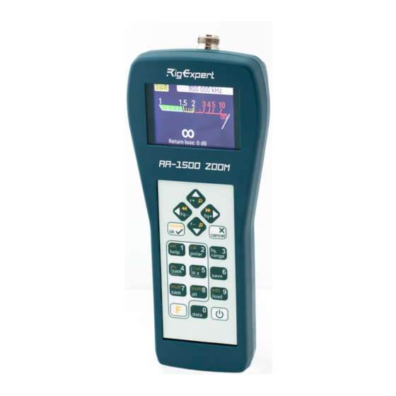
- Page 1 AA-1500 ZOOM RigExpert ® Antenna and cable analyzers User’s manual...
- Page 2 For latest manuals and software updates, please visit http://rigexpert.com...
-
Page 3: Table Of Contents
Table of contents Introduction Operating the AA-1500 ZOOM First time use Main menu Multifunctional keys Connecting to your antenna SWR chart Chart ZOOM Data screen Frequency and range entry Return loss chart R,X chart Smith chart Memory operation SWR mode... -
Page 4: Introduction
Introduction Thank purchasing a RigExpert AA-1500 ZOOM Antenna and Cable Analyzer! We did our best to make it powerful yet easy to use. The analyzer is designed for measuring SWR (standing wave ratio), return loss, cable loss, as well as other parameters of cable and antenna systems in the range of 100 kHz to 1500 MHz. -
Page 5: Operating The Aa-1500 Zoom
USB icon when the analyzer is connected to your computer. You may use hot keys for the quick access to certain tasks. For instance, press (SWR chart) button to open the SWR chart screen immediately. RigExpert AA-1500 ZOOM... -
Page 6: Multifunctional Keys
Multifunctional keys Most keys on the analyzer’s keypad perform several functions. For instance, numbers (1) are used to enter frequency and other numerical parameters. Main functions (2) provide quick access to most common tasks. Alternative functions (3) are executed if the user holds the (Functional) key. -
Page 7: Swr Chart
(Cursor down) key combination to zoom the vertical scale of the chart. Do not forget to press the (OK) key for the new measurement to start. Press (Functional key) and to quickly choose a radio amateur band. RigExpert AA-1500 ZOOM... -
Page 8: Data Screen
Data screen The data screen is available in all chart modes. Press the (Data) key to display various parameters of a load at cursor. Frequency and range entry To enter the center frequency or the sweep range, press the (Frequency, Range) key. -
Page 9: R,X Chart
(Smith chart) key opens a screen where the reflection coefficient is plotted on the Smith chart. For a list of hot keys, press the (Help) key, as usual. A small marker is used to indicate the center frequency. RigExpert AA-1500 ZOOM... -
Page 10: Memory Operation
Memory operation Press the (Save) key to save the chart into one of 100 available memory slots. To retrieve your readings from the memory, press then (Load) key, select a memory slot number and press (OK). To rename any existing memory slot, press (Functional key) (Edit) key combination. -
Page 11: Display All Parameters
• In the series model, impedance is • In the parallel model, impedance is expressed as resistance and reactance expressed as resistance and reactance connected in series: connected in parallel: Z = R + jX Z = R ||+ jX RigExpert AA-1500 ZOOM... -
Page 12: Multiswr Mode
MultiSWR mode Press the (Functional key) and (Multi) key combination to see the SWR at up to five different frequencies. This mode may be useful for tuning multi- band antennas. (Up) and (Down) cursor keys to select a frequency to be set or changed, then press the (Frequency) key to enter a new value. -
Page 13: Applications
The next screen shot shows SWR chart of another car antenna. The actual resonant frequency is about 146.7 MHz, which is too far from the desired one. The SWR at 145.5 MHz is 2.7, which is not acceptable in most cases. RigExpert AA-1500 ZOOM... -
Page 14: Coaxial Lines
Adjusting the antenna When the measurement diagnoses that the antenna is off the desired frequency, the analyzer can help in adjusting it. Physical dimensions of a simple antenna (such as a dipole) can be adjusted knowing the actual resonant frequency and the desired one. Other types of antennas may contain more than one element to adjust (including coils, filters, etc.), so this method will not work. - Page 15 299,792,458 × 0.66 = constant and the velocity factor of the 197,863,022 meters per second particular type of cable, find the speed of - or - electromagnetic wave in this cable. 983,571,056 × 0.66 = 649,156,897 feet per second RigExpert AA-1500 ZOOM...
- Page 16 3. Calculate the physical length of the 197,863,022 / 4,100,000 × (1/4) = cable by dividing the above speed by 12.06 meters the resonant frequency (in Hz) and - or - multiplying the result by the number 649,156,897 / 4,100,000 × (1/4) = which corresponds to the location of this 39.58 feet resonant frequency (1/4, 1/2, 3/4, 1, 5/4,...
- Page 17 Watch the behavior of the reactive component (X) near the zero frequency: ∞ • If the value of X is moving from – to 0, the cable is open-circuited: ∞ • If the value of X is moving from 0 to + , the cable is short-circuited: RigExpert AA-1500 ZOOM...
- Page 18 Making 1/4-λ, 1/2-λ and other coaxial stubs Pieces of cable of certain electrical Example: length are often used as components of 1/4- λ stub for 28.2 MHz, cable is RG- baluns (balancing units), transmission 58 (velocity factor is 0.66) line transformers or delay lines. To make a stub of the predetermined electrical length, 1.
- Page 19 Ohm resistor at the far end. 100 Ohm resistors. 2. Enter the R,X chart mode and make measurement in a reasonably large frequency range (for instance, 0 to 200 MHz). Example 1: Example 2: 50-Ohm cable Unknown cable RigExpert AA-1500 ZOOM...
- Page 20 3. Changing the display range and Example 1: performing additional scans, find a 30.00 MHz – min., 60.00 MHz – max. frequency where R (resistance) reaches Example 2: its maximum, and another frequency 41.00 MHz – max., 88.40 MHz – min. with minimum.
-
Page 21: Measurement Of Other Elements
The analyzer can measure capacitance from a few pF to about 0.1 μF as well as inductance from a few nH to about 100 μH. Since measuring of capacitance and inductance is not a main purpose of RigExpert analyzers, the user will have to gain some experience in such measurements. - Page 22 Unknown inductor Transformers RigExpert analyzers can also be used for checking RF transformers. Connect a 50 Ohm resistor to the secondary coil (for 1:1 transformers) and use SWR chart, R,X chart or Smith chart modes to check the frequency response of the transformer. Similarly, use resistors with other values for non-1:1 transformers.
- Page 23 A one-turn coil (about 10 cm in diameter) connected to the analyzer was placed, co-axially, a few centimeters away from the measured trap. The SWR chart shows a visible dip near 17.4 MHz, which is a resonant frequency of the trap. RigExpert AA-1500 ZOOM...
-
Page 24: Annexes
Annex 1 Optional open-short-load calibration. Specifications RF output: • Connector type: N • Output signal shape: square • Output power: -10 dBm (at 50 Ohm Frequency range: 0.1 to 1500 MHz load) Frequency entry: 1 kHz resolution Power: • Three 1.5V alkaline batteries, type AA Measurement for 25, 50, 75, 100, 150, •... -
Page 25: Annex 2: Precautions
This may cause interference to nearby receivers. If using a personal computer, first connect the cable to the antenna connector of the analyzer, then plug the analyzer to the computer USB port. This will protect the analyzer from static discharges. RigExpert AA-1500 ZOOM... -
Page 26: Annex 3 Tools Menu
Annex 3 Tools menu For the quick access to the the Tools menu, press the key combination. Stub tuner The Stub tuner mode is designed to help making or checking 1/4-λ or 1/2-λ coaxial stubs. Connect either open or short circuited cable to the analyzer and press (OK) to start. - Page 27 To find the velocity factor of an unknown cable, press the (Down) key and enter the physical length, then press (OK). The velocity factor depends on a type of your transmission line. For instance, RG-58 cable with polyethylene insulator has VF=0.66. RigExpert AA-1500 ZOOM...
- Page 28 Cable loss To measure the loss in a coaxial cable, connect a piece of a cable to the antenna connector of the analyzer. Make sure the far end of the cable is open circuited. Press (OK) to start. Next, short circuit the far end of the cable and press (OK) to continue.
- Page 29 (Left) and (Right) cursor keys to find the location where the impedance is stable. The result is shown at the bottom left corner of the screen. (Up) and (Down) key combinations to change the scale, if needed. RigExpert AA-1500 ZOOM...
- Page 30 Self tests There are several built-in self tests in the AA-1500 ZOOM analyzer, which can be run by the user to make sure the analyzer is working properly. Make sure all cables or adapters are disconnected from the antenna connector of your analyzer, then press (OK) to start the first test (Detector test).
-
Page 31: Annex 4: Setup Menu
• Freq. corr. – frequency correction of the analyzer’s oscillator • Data points – select a number of data points for each frequency sweep • Reset settings – reset the analyzer to factory defaults • Clear saved charts – clear all memory slots RigExpert AA-1500 ZOOM... -
Page 32: Annex 5 Tdr Mode
Annex 5 TDR mode Theory Time domain reflectometers (TDR) are electronic instruments used for locating faults in transmission lines. A short electrical pulse is sent over the line, and then a reflected pulse is observed. By knowing the delay between two pulses, the speed of light and the cable velocity factor, the DTF (distance- to-fault) is calculated. - Page 33 Unlike many other commercially-available reflectometers, RigExpert AA-650 ZOOM does not send pulses into the cable. Instead, another technique is used. First, R and X (the real and the imaginary part of the impedance) are measured over the whole frequency range (up to 1500 MHz). Then, the IFFT (Inverse Fast Fourier Transform) is applied to the data.
- Page 34 User’s manual...
- Page 35 Pressing (Data) opens a data screen which displays numerical values of impulse and step response coefficients, as well as Z (estimated impedance) at cursor. The key will display the help screen, as usual. RigExpert AA-1500 ZOOM...
-
Page 36: Annex 6 Calibration
Annex 6 Calibration Although RigExpert AA-1500 ZOOM is designed for high performance without any calibration, an open-short-load calibration may be applied for better precision. The standards used for calibration should be of high quality. This requirement is especially important for high frequencies (100 MHz and upper). Three different calibration standards should be used: an “open”, a “short”... - Page 37 You may connect calibration standards to the far end of a cable, so the cable will be “nulled”. apply calibration, press key combination in any measurement mode. The “CAL“ mark will appear at the bottom left corner of the screen. RigExpert AA-1500 ZOOM...
-
Page 38: Annex 7: Dummy Loads
Annex 7 Dummy loads Amphenol 202109-10 1 Watt terminator plug Low SWR 50 Ohm dummy loads are not all equal. For calibration (see page 32), please use low-power RF terminators which provide low SWR over the wide frequency range. High-power terminators, especially connected via long cables, are suitable... - Page 39 2004/108/EC ( the EMC Directive ). The technical documentation relevant to the above equipment will be held at: SEDAM Communications Limited Old Mill Cottage, Shillington Rd, Gravenhurst, MK45 4JE, The United Kingdom /Ashot Andrieiev/ June 23, 2020 Director RigExpert AA-1500 ZOOM...
- Page 40 This symbol is only valid in the European Union (EU). If you wish to discard this product, please contact your local authorities or dealer and ask for the correct method of disposal. http://www.rigexpert.com Copyright © 2020 Rig Expert Ukraine Ltd. “RigExpert” is a registered trademark of Rig Expert Ukraine Ltd. Doc. date: 23-June-2020...
Need help?
Do you have a question about the AA-1500 ZOOM and is the answer not in the manual?
Questions and answers