Advertisement
Quick Links
Instruction
Manual
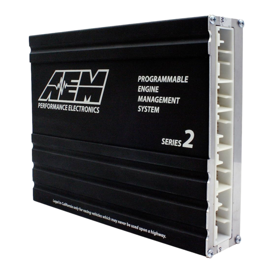
Series 2 Plug & Play EMS
2006–2008 Honda S2000 AP2 F22C1
THIS PRODUCT HAS LEGAL RESTRICTIONS.
READ THIS BEFORE INSTALLING/USING!
WARNING! THIS IS A RACE ONLY PRODUCT MANUFACTURED AND SOLD FOR INSTALLATION ON VEHICLES DESIGNED TO BE USED
SOLELY FOR COMPETITION PURPOSES. ONCE THIS PART IS INSTALLED, THE VEHICLE MAY NEVER BE USED, OR REGISTERED
OR LICENSED FOR USE, ON A PUBLIC ROAD OR HIGHWAY. IF YOU INSTALL THIS PART ON YOUR VEHICLE AND USE THE VEHICLE
ON A PUBLIC ROAD OR HIGHWAY, YOU WILL VIOLATE THE CLEAN AIR ACT AND MAY BE SUBJECT TO PERSONAL CIVIL OR
CRIMINAL LIABILITY, INCLUDING FINES OF UP TO $4,819 PER DAY.
IT IS THE RESPONSIBILITY OF THE INSTALLER AND/OR USER OF THIS PRODUCT TO ENSURE THAT IT IS USED IN COMPLIANCE
WITH ALL APPLICABLE LAWS AND REGULATIONS. IF THIS PRODUCT WAS PURCHASED IN ERROR, DO NOT INSTALL AND/OR USE
IT. THE PURCHASER MUST ARRANGE TO RETURN THE PRODUCT FOR A FULL REFUND.
THIS POLICY ONLY APPLIES TO INSTALLERS AND/OR USERS WHO ARE LOCATED IN THE UNITED STATES; HOWEVER
CUSTOMERS WHO RESIDE IN OTHER COUNTRIES SHOULD ACT IN ACCORDANCE WITH THEIR LOCAL LAWS AND REGULATIONS.
WARNING!
Improper installation and/or adjustment of this product can result in major engine/vehicle damage. For
technical assistance visit our dealer locator to find a professional installer/tuner near you.
Note: AEM holds no responsibility for any engine damage or personal injury that results from the misuse
of this product, including but not limited to injury or death caused by the mishandling of methanol.
Enter value
AEM Performance Electronics, 2205 126th Street Unit A, Hawthorne, CA 90250
30-6053
STOP!
AEM Performance Electronics
Phone: (310) 484-2322 Fax: (310) 484-0152
http://www.aemelectronics.com
Instruction Part Number: 10-6053
Document Build 1/21/2021
Advertisement

Related Manuals for AEM Performance Electronics 30-6053 Series


Summary of Contents for AEM Performance Electronics 30-6053 Series
- Page 1 Enter value AEM Performance Electronics AEM Performance Electronics, 2205 126th Street Unit A, Hawthorne, CA 90250 Phone: (310) 484-2322 Fax: (310) 484-0152 http://www.aemelectronics.com...
-
Page 2: Tuning Notes
Multiple calibrations may be supplied for each EMS; additional details of the test vehicle used to generate each calibration can be found in the Calibration Notes section for that file. Please visit the AEM Performance Electronics Forum at http://www.aemelectronics.com and register. We always post the most current strategy release, PC Software and startup calibrations online. -
Page 3: Installation
EMS. The throttle will still be cut as normal, but the traction and stability control warning lights will stay on after the system is no longer activated and will reset when the vehicle is turned off. © 2021 AEM Performance Electronics... - Page 4 Please follow this suggested wiring diagram when adding new accessories and retaining original accessories such as UEGO gauges, MAP sensors, MAF sensors, IAT sensors, or switches for use with the EMS. Note that wire polarity is not important for the Air Temperature sensor. © 2021 AEM Performance Electronics...
- Page 5 Remove kick panel that covers the original ECU and the plastic cover on the lower driver’s side door sill. The door sill cover is held in with plastic clips as shown below. Clips holding sill cover Remove sill cover © 2021 AEM Performance Electronics...
- Page 6 Tap pin 3 on the red/blue TPS wire on the stock wiring harness using the provided wire-tap. It is located on the white 6-pin connector near the stock ECU shown below. Tap pin 3 (red/blue wire) on 6-pin connector © 2021 AEM Performance Electronics...
- Page 7 AEM ECU. Do not cut any of the wires in the factory wiring harness to remove them. Next to the stock ECU on the stock wiring harness, the A and B connectors should be routed underneath the D and E connectors to make them easier to install. Reroute connectors Carefully remove ECU connectors © 2021 AEM Performance Electronics...
- Page 8 Reinstall the covers in the reverse of removal. Make sure that the cover that goes over the original ECU and now the adapter harness fits so that it is not contacting the clutch pedal. © 2021 AEM Performance Electronics...
- Page 9 (.cal) that most closely matches the vehicle’s configuration to be tuned. Check the Notes section of the calibration for more info about the vehicle it was configured for. These files can be found in the following folder: C:\Program Files\AEM\AEMTuner\Calibrations\Honda - Acura\ © 2021 AEM Performance Electronics...
- Page 10 “B” points to the red mark that is located 5° before top dead center. c) Note: This calibration needs to be properly tuned before driving the vehicle. It is intended for racing vehicles and may not operate smoothly at idle or part-throttle. NEVER TUNE A VEHICLE WHILE DRIVING. © 2021 AEM Performance Electronics...
- Page 11 TPS-to-Load table to generate an artificial Engine Load signal using the Throttle input.) This may allow the engine to sputter or start but not continue running properly. © 2021 AEM Performance Electronics...
-
Page 12: Application Notes
All switch input pins must connect to ground, the switch should not provide 12V power to the EMS because that will not be detected as on or off. Connecting 12V power to the switch input pins may damage your EMS and void your warranty. © 2021 AEM Performance Electronics... - Page 13 Injector 4 (Injector 4 on EMS) intercepted Injector 3 (Injector 3 on EMS) intercepted Injector 2 (Injector 2 on EMS) intercepted Injector 1 (Injector 1 on EMS) intercepted VTEC solenoid valve (HS 1 on EMS) intercepted © 2021 AEM Performance Electronics...
- Page 14 B17 Intake Air Temperature signal (AIT on EMS) tapped B18 Alternator Control signal (LS 3 on EMS) B19 Throttle Actuator signal SEFD B20 Throttle Actuator signal SEDF B21 Evap Emission Canister purge valve B22 -- B23 -- B24 -- © 2021 AEM Performance Electronics...
- Page 15 Cruise Control set switch Cruise Control main switch Cruise Control resume switch Brake pedal position switch Cruise Control clutch signal D10 -- D11 -- D12 -- D13 -- D14 -- D15 Throttle Actuator Relay D16 -- D17 -- © 2021 AEM Performance Electronics...
- Page 16 Plug and Play system comes with this pin configured for proper operation of this device, though it is still available for reassignment by the end user. Available Pin is not currently allocated and is available for use. Dedicated Pin assignment is fixed and cannot be changed. © 2021 AEM Performance Electronics...
- Page 17 Available, 0–5V mass air flow sensor signal Available, exhaust gas temperature sensor number 3, EGT 3 Input jumper set for 0–5V input Sensor ground Output Available, filtered ground for sensors Switch 1 Input Available, switched ground input signal number 1 © 2021 AEM Performance Electronics...
- Page 18 Output Available, power ground PW 1 Output Available, pulse width modulated switched ground, 1.5A max Knock 2 Input Available, 0–5V knock sensor signal (connected to C22) Idle 8 Output Available, switched +12V power, 1.5A max © 2021 AEM Performance Electronics...
- Page 19 +5V sensor power Output Available, +5V sensor power Spare speed (T4) Input Available, 0–5V speed sensor signal Timing ground Output Available, filtered ground for speed sensors (T1–T4) Timing ground Output Available, filtered ground for speed sensors (T1–T4) © 2021 AEM Performance Electronics...
- Page 20 Baro volts Input Available, barometric pressure sensor signal PW 2 Output Available, boost solenoid pulse-width modulated switched ground AEM EMS Pin Numbering *** Important: Wire View of AEM EMS. Reference diagram below for pin location. *** © 2021 AEM Performance Electronics...
-
Page 21: Relay Pinout
Stock ECU A5 Input Dedicated Ground to +5V line AEM EMS D6 Output Dedicated, used to power AEM EMS off properly Ground Stock ECU A5 Input Dedicated Not used Relay Pin Numbering Wire View of Relay © 2021 AEM Performance Electronics... - Page 22 12 MONTH WARRANTY AEM Performance Electronics warrants to the consumer that all AEM ELECTRONICS products will be free from defects in material and workmanship for a period of twelve months from date of the original purchase. Products that fail within this 12-month warranty period will be repaired or replaced when determined by AEM that the product failed due to defects in material or workmanship.
Need help?
Do you have a question about the 30-6053 Series and is the answer not in the manual?
Questions and answers