Table of Contents
Advertisement
Instruction
Manual
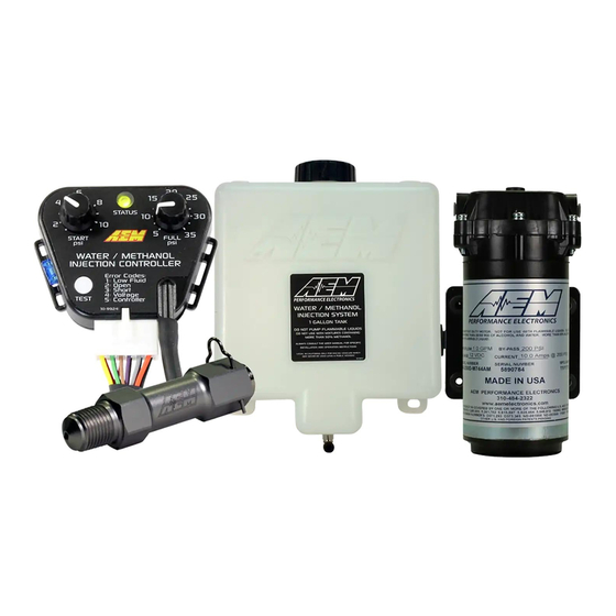
Water/Methanol Injection Kit V2
Standard Controller - Internal MAP
THIS PRODUCT HAS LEGAL RESTRICTIONS.
THIS PRODUCT MAY BE USED SOLELY ON VEHICLES USED IN SANCTIONED COMPETITION WHICH MAY NEVER BE USED
UPON A PUBLIC ROAD OR HIGHWAY, UNLESS PERMITTED BY SPECIFIC REGULATORY EXEMPTION. (VISIT THE "EMISSIONS"
PAGE AT
HTTP://WWW.SEMASAN.COM/EMISSIONS
IT IS THE RESPONSIBILITY OF THE INSTALLER AND/OR USER OF THIS PRODUCT TO ENSURE THAT IT IS USED IN
COMPLIANCE WITH ALL APPLICABLE LAWS AND REGULATIONS. IF THIS PRODUCT WAS PURCHASED IN ERROR, DO NOT
INSTALL AND/OR USE IT. THE PURCHASER MUST ARRANGE TO RETURN THE PRODUCT FOR A FULL REFUND.
THIS POLICY ONLY APPLIES TO INSTALLERS AND/OR USERS WHO ARE LOCATED IN THE UNITED STATES; HOWEVER
CUSTOMERS WHO RESIDE IN OTHER COUNTRIES SHOULD ACT IN ACCORDANCE WITH THEIR LOCAL LAWS AND
REGULATIONS.
WARNING!
Improper installation and/or adjustment of this product can result in major engine/vehicle damage. For
technical assistance visit our dealer locator to find a professional installer/tuner near you.
Note: AEM holds no responsibility for any engine damage or personal injury that results from the
misuse of this product, including but not limited to injury or death caused by the mishandling of
methanol.
AEM Performance Electronics, 2205 126th Street Unit A, Hawthorne, CA 90250
P/N 30-3300
1-Gallon Tank
STOP!
READ THIS BEFORE INSTALLING/USING!
FOR STATE BY STATE DETAILS.)
AEM Performance Electronics
Phone: (310) 484-2322 Fax: (310) 484-0152
http://www.aemelectronics.com
Instruction Part Number: 10-3300
Document Build 5/14/2020
Advertisement
Table of Contents

Related Manuals for AEM Performance Electronics 30-3300


Summary of Contents for AEM Performance Electronics 30-3300
- Page 1 AEM Performance Electronics AEM Performance Electronics, 2205 126th Street Unit A, Hawthorne, CA 90250 Phone: (310) 484-2322 Fax: (310) 484-0152 http://www.aemelectronics.com Instruction Part Number: 10-3300...
- Page 2 Note: AEM holds no responsibility for any engine damage or personal injury that results from the misuse of this product, including but not limited to injury or death caused by the mishandling of methanol. © 2020 AEM Performance Electronics...
-
Page 3: Specifications
· Two system status LED indicators; shows pump duty cycle and system errors · Pump open and short detection and indication; works even if the pump is off · Test button that manually triggers pump © 2020 AEM Performance Electronics... -
Page 4: Parts List
Fitting, 1/4 Tube, Cliptype 35-4561 Butt Connector, 8-360 Spring 35-4562 14-16 AWG (blue) Butt Connector, 8-361 Check Valve 35-4563 18-22 AWG (red) Ring Terminal, 8-354 Check Valve Seal 35-4570 14-16 AWD (blue) Retaining Clip 35-4565 © 2020 AEM Performance Electronics... -
Page 5: Installation
Water/Methanol Injection V2 INSTALLATION Diagram *Viewed from Wire Side of Connector NOTE: THIS KIT INCLUDES NEW STYLE INJECTOR NOZZLES THAT HAVE INTERNAL CHECK VALVES. AN EXTERNAL CHECK IS NO LONGER NEEDED OR INCLUDED IN THIS KIT. © 2020 AEM Performance Electronics... -
Page 6: Installation Checklist
Cut and install nylon hose from pump to nozzle. Ensure that the hose is not resting, near, or running on any moving or “hot” parts. Tune Engine Engine tuning is usually required in order to maximize potential power gain. © 2020 AEM Performance Electronics... - Page 7 IMPORTANT: Use the supplied large OD washer to spread the load on the plastic mounting ears of the tank. DO NOT OVERTIGHTEN! Nuts should just be snug; they are locking nuts and will not loosen. Over-tightening will crack the plastic and cause leaks and void the warranty. © 2020 AEM Performance Electronics...
- Page 8 If you need to extend the wires to mount the controller use at least 16 AWG wire for the pump and controller ground circuits and 18 AWG for the remainder. © 2020 AEM Performance Electronics...
- Page 9 LED will be off. If there are no errors and the pump is on, the LED intensity will vary with the pump speed. If there are any errors, they will be indicated by flashing the LED. Boost Pressure Hose Using the supplied vacuum tee and rubber hose, tap into a manifold pressure (vacuum/boost) line. © 2020 AEM Performance Electronics...
-
Page 10: Nozzle Selection
5140 1028 1285 1542 3938 5507 1101 1377 1652 4200 5874 1175 1469 1762 4463 6241 1248 1560 1872 4725 6608 1322 1652 1983 4988 6976 1395 1744 2093 1000 5250 7343 1469 1836 2203 © 2020 AEM Performance Electronics... -
Page 11: Nozzle Assembly
1. Select your atomizing pintle of choice using the nozzle selection table. Once you have decided on the size of the pintle for your application, use the table below to help you identify the correct pintle. Pintle Size 250cc 500cc 1000cc Picture (Pintle Head) Slot Cupped End Flat Picture (Pintle Stem) © 2020 AEM Performance Electronics... - Page 12 In case the check valve comes apart during disassembly, the diagram below shows how the check valve snaps together. No adhesive is required. The actual EPDM valve will not come out of the valve body. © 2020 AEM Performance Electronics...
-
Page 13: Fluid Compatibility
Check and repair any leaks. Drain the water out of the tank and install the nozzle. Fluid Compatibility Under NO circumstances should any hydrocarbon based fuel ever be used with this system. Water and methanol are the ONLY fluids to be used. © 2020 AEM Performance Electronics... -
Page 14: System Errors
8.5V–16V. operating properly. - BoostSafe Enabled Controller An internal controller error Call AEM Tech Support - Pump will NOT Error has been detected. @ 1-800-423-0046 continue to run © 2020 AEM Performance Electronics... -
Page 15: Troubleshooting Diagram
Water/Methanol Injection V2 Troubleshooting Diagram © 2020 AEM Performance Electronics... -
Page 16: Status Led
The controller has an on-board Status LED. This will mimic the operation of the external LED. Upon startup the current mode is flashed in green on the status LED. It will flash error codes in red as well as illuminate with varying intensity as a function of flow in green. © 2020 AEM Performance Electronics... -
Page 17: Test Button
LED. Once the button is released the controller will continue to function normally. You can also tell what mode has been selected by listening for the buzzing sound in the pump. Repeating this operation will toggle between the two modes. © 2020 AEM Performance Electronics... - Page 18 To set this up the “Full PSI” knob must be set to a lower value then the “Start PSI” knob. This means as soon as the boost exceeds the “Start PSI” threshold the pump will begin pumping at its maximum flow since it has passed both the start and the full requirements. © 2020 AEM Performance Electronics...
-
Page 19: Engine Tuning
The injector nozzle should be cleaned periodically. Disassemble the nozzle and clean it with a suitable cleaner until all debris is removed. If excessive contamination is found, check the rest of the system for the source. © 2020 AEM Performance Electronics... - Page 20 5-Gallon Tank – AEM P/N 30-3320 Upgrade to a 5-gallon tank to maximize your fluid holding capacity. Includes level sensor and mounting hardware. © 2020 AEM Performance Electronics...
-
Page 21: 12 Month Limited Warranty
12 MONTH LIMITED WARRANTY AEM Performance Electronics warrants to the consumer that all AEM ELECTRONICS products will be free from defects in material and workmanship for a period of twelve months from date of the original purchase. Products that fail within this 12-month warranty period will be repaired or replaced when determined by AEM that the product failed due to defects in material or workmanship.
Need help?
Do you have a question about the 30-3300 and is the answer not in the manual?
Questions and answers