Table of Contents
Advertisement
Quick Links
Air-Cooled Scroll
Compressor Condensing Units
Installation, Operation, and
Supersedes: QCC2-NM1 (1220)
Form QCC2-NM1 (521)
Maintenance
035-26916-000
QCC2015CEE – QCC2070CEE
Air-Cooled Scroll Compressor Condensing Units
Style E (60 Hz)
15 ton to 80 ton
50 kW to 280 kW
R-410A
Issue Date:
May 20, 2021
Products are produced at a
f a c i l i t y w h o s e q u a l i t y -
management systems are
ISO9001 certified.
Advertisement
Table of Contents
Troubleshooting

Summary of Contents for Quantech QCC2015CEE
- Page 1 Air-Cooled Scroll Compressor Condensing Units Installation, Operation, and Supersedes: QCC2-NM1 (1220) Form QCC2-NM1 (521) Maintenance 035-26916-000 QCC2015CEE – QCC2070CEE Air-Cooled Scroll Compressor Condensing Units Style E (60 Hz) 15 ton to 80 ton 50 kW to 280 kW R-410A Issue Date:...
- Page 2 All wiring must be in accordance with Quantech published specifications and must be performed only by a qualified electri- cian. Quantech will NOT be responsible for damage/problems resulting from improper connections to the controls or application of improper control signals.
- Page 3 If there is any question this document is subject to change without notice. regarding the applicability of these documents, rig- Quantech makes no commitment to update or provide ging, lifting, and operating/service personnel should current information automatically to the manual or verify whether the equipment has been modified and product owner.
- Page 4 Refrigerant level E = R-410a Scroll compressor Across-the- Unit High efficiency unit line start Model 015C Voltage code Quantech Air-Cooled 020C -17 = 208-3-60 Scroll Condensing Units 025C -28 = 230-3-60 030C -40 = 380-3-60 040C -46 = 460-3-60 045C...
-
Page 5: Table Of Contents
Refrigerant Piping Reference ......................... 35 Filter Driers / Sight Glasses/ Txv’s ......................... 35 SECTION 5 – TECHNICAL DATA ........................39 SECTION 6 – COMMISSIONING .........................97 Preparation – Power Off ..........................97 Preparation – Power On ..........................98 Equipment Pre-Startup and Startup Checklist ....................99 QUANTECH... - Page 6 SECTION 10 – MAINTENANCE .........................153 Important ..............................153 Compressors ..............................153 Condenser Fan Motors ..........................153 Condenser Coils ............................153 Operating Parameters ..........................153 On-Board Battery Back-Up ........................... 153 Overall Unit Inspection ..........................153 BACnet, Modbus and YorkTalk 2 Communications ..................154 QUANTECH...
- Page 7 Form QCC2-NM1 Issue Date: 5/20/2021 List of figures FIGURE 1 - Quantech Air-Cooled Scroll Compressor Condensing Unit ..............13 FIGURE 2 - Unit Components Front ........................18 FIGURE 3 - Power Panel Components ........................19 FIGURE 4 - Power Panel / Control Components ....................20 FIGURE 5 - Refrigerant Flow Diagram ........................25...
- Page 8 TABLE 31 - Minimum, Maximum And Default Values ..................155 TABLE 32 - Values Required For Bas Communication ..................156 TABLE 33 - Real Time Error Numbers .........................156 TABLE 34 - BACnet and Modbus Communications Data Map ................158 TABLE 35 - YorkTalk 2 Communications Data Map .....................163 QUANTECH...
-
Page 9: Section 1 - General Equipment Information And Safety
NFPA 70 (National Elec tric Code), ASHRAE/ANSI 15 Safety code for mechanical refrigeration, and are cETL Warranty listed. All units are produced at an ISO 9000-registered Quantech warrants all equipment and materials against facility. defects in workmanship and materials for a period of Compressors... -
Page 10: Safety And Quality
Air Conditioning Equipment. This manual and any other document supplied with the unit are the property of Quantech which reserves • Conform to Intertek Testing Services, formerly all rights. They may not be reproduced, in whole or in... - Page 11 No the unit. attempt should be made to gain access to the control panel or electrical enclosures during normal operation of the unit. QUANTECH...
- Page 12 Form QCC2-NM1 Issue Date: 5/20/2021 THIS PAGE IS INTENTIONALLY LEFT BLANK QUANTECH...
-
Page 13: Section 2 - Product Description
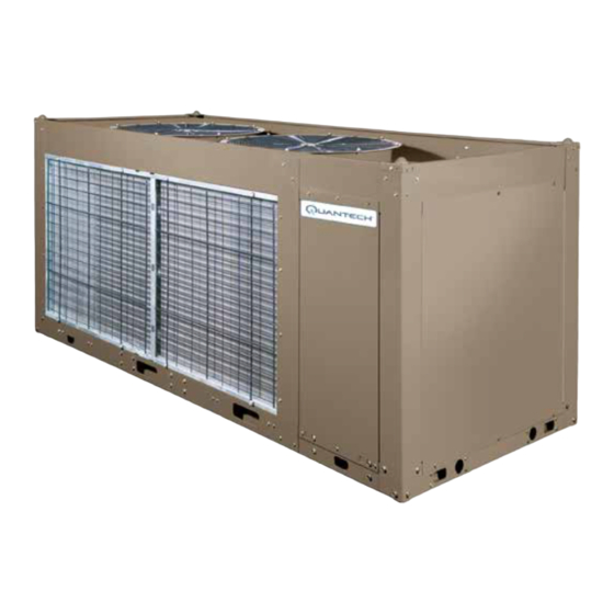
NFPA 70 (National Elec tric Code), ASHRAE/ANSI 15 sure of the coil is 650 psig (45 bar). Safety code for mechanical refrigeration, and are cETL listed. All units are produced at an ISO 9000-registered facility. Figure 1 - Quantech Air-Cooled Scroll Compressor Condensing Unit QUANTECH... -
Page 14: Microcomputer Control Center
• An RS-232 port, in conjunction with the press-to- • Low ambient temperature cutout setting print button, is provided to allow hard copy print- outs via a separate printer (by others). • English or Metric data • Suction pressure cutout setting • Each system suction pressure QUANTECH... -
Page 15: Building Automation System Interface
(load) limiting depending on model. • No cooling load condition • The standard control panel can be directly con- • Day, date and time nected to a Quantech Building Automated Sys- tem. • Daily start/stop times Communications • Holiday status •... -
Page 16: Accessories And Options
These factory mounted capacitors will correct unit allows models to sense and display discharge pressure. compressor to a power factor between 0.90 and 0.95. This is recommended for brine chilling applications. This option is included with either the low or high am- bient kits. QUANTECH... - Page 17 UV resistance. comparable to copper-fin coils in typical seashore loca- tions. Either these or the post-coated coils (below) are recommended for units being installed at the seashore or where salt spray may hit the unit. QUANTECH...
-
Page 18: Figure 2 - Unit Components Front
Level adjusting, spring type 1 in. (25.4 mm) or seismic pitch fans on these factory mounted devices. deflection or neoprene pad isolators for mounting un- der unit base rails. (Field-Mounted) Unit components MICROPANEL FANS COMPRESSORS CONDENSER COILS Figure 2 - Unit Components Front QUANTECH... -
Page 19: Figure 3 - Power Panel Components
Form QCC2-NM1 SECTION 2 – PRODUCT DESCRIPTION Issue Date: 5/20/2021 Power panel components DISCONNECT SWITCH FAN FUSES FAN CONTACTORS FAN CONTACTOR COMPRESSOR OVERLOADS XTBF1 COMPRESSOR CONTACTORS LD13247 Figure 3 - Power Panel Components QUANTECH... -
Page 20: Figure 4 - Power Panel / Control Components
SECTION 2 – PRODUCT DESCRIPTION Issue Date: 5/20/2021 Power panel/control components FAN FUSES MICROCOMPUTER CONTROL FAN CONTACTORS CONTROL RELAY CENTER MICROPANEL DISPLAY KEYPAD COMPRESSOR OVERLOADS XTBC1 MICROBOARD XTBC2 COMPRESSOR XTBF2 CONTACTORS LD13248 Figure 4 - Power Panel / Control Components QUANTECH... -
Page 21: Basic Unit
:200 / 3 / 60 C : Unit :230 / 3 / 60 :Design Series :380 / 3 / 60 QC :Quantech Air-Cooled Scroll Condensing Units :460 / 3 / 60 :575 / 3 / 60 :380-415 / 3 / 50... - Page 22 Hot Gas Bypass Required - 1 Circuit HGBP Hot Gas Bypass (PIN 33) Hot Gas Bypass Required - 2 Circuits Special Hot Gas Bypass Required No Option Required GAUGE PIN 34 Special Quote No Option Required OVERLOAD PIN 35 Special Quote QUANTECH...
- Page 23 SR Documents (PIN 50) Base and Material Documents Base and Witness Documents Special Quote No Option Required PIN51 PIN 51 Special Quote Standard Low Sound Fans Required FANS Sound Fans (PIN 52) Ultra Low Sound Fans Required Special Sound Fans Required QUANTECH...
- Page 24 Pump Package Options (PIN 60) Special Quote Plant of Mfg (PIN 61) Plant Of Manufacture - Monterrey Curitiba, Brazil Mexico, ES Mfg location Monterrey, BE San Antonio, Texas Yorkworks Configuration Version {YW/CV} YorkWorks version Yorkworks Upload Version {YW/UV} Special quote Special Quote QUANTECH...
-
Page 25: Figure 5 - Refrigerant Flow Diagram
Form QCC2-NM1 SECTION 2 – PRODUCT DESCRIPTION Issue Date: 5/20/2021 Refrigerant flow diagram LD04284A Figure 5 - Refrigerant Flow Diagram QUANTECH... -
Page 26: Figure 6 - Process And Instrumentation Diagram
Low pressure vapor enters the compres- ing takes place before returning to the DX Coil. sor where pressure and superheat are increased. The QUANTECH... -
Page 27: Section 3 - Handling And Storage
See Instruction manual, Form 50.15-NM, for more infor- mation and details. Major damage must be reported immediately to your local Quantech Sales Representative. LD14326 Figure 7 - Unit Rigging QUANTECH... - Page 28 The unit must only be lifted by the base frame at the points provided. Never move the unit on rollers, or lift the unit using a forklift truck. QUANTECH...
-
Page 29: Section 4 - Installation
The units must be installed with sufficient clearances the Quantech Engineering Guide for the specific con- for air entrance to the condenser coil, for air discharge densing unit model. Sound blankets for the compres- away from the condenser, and for servicing access. -
Page 30: Spring Isolators (Optional)
No more than 3 feet (1 meter) of light construction ductwork should be supported by the unit. Where cross winds may occur, any ductwork must be supported to prevent side loading on the unit. QUANTECH... - Page 31 33%, 40%, 50%, 66% or 80%, depend- ing on the number of compressors on unit.) The field connections are wired to XTBC1 – Terminals 13 to 21, and work in conjunction with the PWM inputs. A de- QUANTECH...
-
Page 32: High Pressure Cutout
50. the user. Evaporator blower start contacts QUANTECH ASSUMES NO WARRANTY RE‑ For constant fan operation: Terminal block XTBC2 - SPONSIBILITY FOR SYSTEM OPERATION terminals 23 to 24, are normally open contacts that can... -
Page 33: Table 1 - Fitting Equivalent Lengths
2.6 ft. (8 m) 7/8 (22) 60.9 92.8 2-1/8 in. (54 mm) 5.2 ft. (1.6 m) 3.4 ft. (1 m) 1-1/8 (29) 60.9 158.3 2-5/8 in. (67 mm) 6.5 ft. (20 m) 4.2 ft. (1.3 m) 1-3/8 (35) 60.9 241.1 QUANTECH... -
Page 34: Table 3 - Miscellaneous Liquid Line Pressure Drops
7/8" for the optional factory mounted hot gas bypass valve. 7. For more information, refer to either the YORK DX Piping Application Guide (Form 050.40-ES2) or the ASHRAE Refrigeration Handbook. Hot gas bypass is only available for refrigerant system number 1. QUANTECH... -
Page 35: Oil Traps
The calculat- Liquid line filter driers, sight glass, and TXV’s are ed information was based on maintaining a minimum field supplied for each refrigerant circuit. of 1000 fpm (5.08 m/s) refrigerant vapor velocity at full load. QUANTECH... -
Page 36: Figure 8 - Single-Point Supply Connection - Terminal Block, Non-Fused Disconnect Switch
DISCHARGE AIR QUABBIN 930421-2 J6-2 SHIELD SENSOR WITH OR EQUIVALENT MOUNTING BRACKET BLK (SIGNAL) BLK (SIGNAL) RED (+5 VDC) RED (+5 VDC) DRAIN (GND) DRAIN (GND) J6 PIN IDENTIFICATION LD13345a ON I/O Figure 9 - Discharge Air Sensor Field Wiring QUANTECH... -
Page 37: Figure 10 - Control Wiring
NO can result in damage to the evaporator LETHAL VOLTAGES are present inside and unit as a result of the chilled liquid the panel AFTER disconnecting power, freezing. BEFORE working on equipment. Figure 10 - Control Wiring QUANTECH... - Page 38 Form QCC2-NM1 Issue Date: 5/20/2021 THIS PAGE IS INTENTIONALLY LEFT BLANK QUANTECH...
-
Page 39: Section 5 - Technical Data
1. For leaving brine temperature below 40°F (4.4°C), contact your nearest Quantech Sales Representative for application requirements. 2. For leaving water temperature higher than 55°F (12.8°C), contact the nearest Quantech Sales Representative for application guidelines. 3. The evaporator is protected against freezing to -20°F (-28.8°C) with an electric heater as standard. -
Page 40: Table 6 - Physical Data (English)
1150 Total Chiller CFM 10670 10670 24600 24600 39500 39500 43333 43333 43333 Ckt. 1 Number of fans Ckt. 2 Condenser Fans, Fan Power hp/fan Ultra Quiet Fan RPM Total Chiller CFM 24600 24600 39500 39500 43333 43333 43333 QUANTECH... -
Page 41: Table 7 - Micro Panel Power Supply
LETHAL VOLTAGES are present inside and unit as a result of the chilled liquid the panel AFTER disconnecting power, freezing. BEFORE working on equipment. Table 8 - Voltage Range VOLTAGE CODE UNIT POWER MINIMUM MAXIMUM 200-3-60 230-3-60 380/415-3-60 460-3-60 380/415-3-50 575-3-60 QUANTECH... - Page 42 FULL LOAD AMPS -50 = 380/415-3-50 HERTZ -58 = 575-3-60 MAXIMUM MINIMUM CIRCUIT AMPACITY MINIMUM MIN NF MINIMUM NON FUSED RATED LOAD AMPS S.P. WIRE SINGLE POINT WIRING UNIT MTD SERV SW UNIT MOUNTED SERVICE (NON-FUSED DISCONNECT SWITCH) LOCKED ROTOR AMPS QUANTECH...
- Page 43 2.9 14.6 2.9 14.6 45.4 45.4 43.5 43.5 25.1 25.1 4.5 22.3 24.2 24.2 4.5 22.3 045C 20.7 20.7 20.7 20.7 3.4 17.2 3.4 17.2 16.6 16.6 2.9 14.6 2.9 14.6 20.7 20.7 See Electrical Notes on page 47. QUANTECH...
- Page 44 7.6 30.9 59.9 59.9 7.6 30.9 71.2 71.2 55.5 55.5 41.1 41.1 4.5 22.3 4.5 22.3 070C 33.9 33.9 26.4 26.4 33.9 33.9 3.4 17.2 26.4 26.4 3.4 17.2 27.1 27.1 2.9 14.6 21.1 21.1 2.9 14.6 33.9 33.9 26.4 26.4 QUANTECH...
-
Page 45: Table 9 - Lug Ranges
4 AWG – 300 kcmil 4 AWG – 300 kcmil 6 AWG – 350 kcmil 4 AWG – 300 kcmil 4 AWG – 300 kcmil 6 AWG – 350 kcmil 4 AWG – 300 kcmil 4 AWG – 300 kcmil QUANTECH... - Page 46 Form QCC2-NM1 SECTION 5 – TECHNICAL DATA Issue Date: 5/20/2021 THIS PAGE IS INTENTIONALLY LEFT BLANK QUANTECH...
- Page 47 Pump Contactor Part Wiring And Items Shown Thus Are Not - KP (Including Coil Suppressor) Supplied By York - KT Relay Timer Items Thus Enclosed Form A Compressor Motor Components Or Sets Of Components - MF Motor Fan 035-21966-101 REVG QUANTECH...
- Page 48 All sources of supply shown on this diagram to be taken from one main isolator, not shown or supplied by Quantech. Green and yellow wire is used for earth, multi-colored cable used for low voltage. Red wire used for AC Control, blue wire for neutral, black wire for AC and DC power.
- Page 49 Fitted on units with single phase motors only Fitted on units with low ambient option only Only fitted on units with an acoustic kit Only fitted on heat recovery units Only fitted on condensing units Omitted on condensing units 035-21966-101 REVG QUANTECH...
- Page 50 Form QCC2-NM1 SECTION 5 – TECHNICAL DATA Issue Date: 5/20/2021 QCC2015C-QCC2030C Low sound QCC2025C-030C Ultra low sound (460 V and 380-415 V 50 Hz) LD22066a Figure 11 - Control Wiring Diagram, Single Circuit, IPU II QUANTECH...
-
Page 51: Figure 11 - Control Wiring Diagram, Single Circuit, Ipu Ii
Form QCC2-NM1 SECTION 5 – TECHNICAL DATA Issue Date: 5/20/2021 035-21472-401 REV E 035-21472-401 REV E LD22066b Figure 11 - Control Wiring Diagram, Single Circuit, Ipu Ii (Cont’d) QUANTECH... - Page 52 Form QCC2-NM1 SECTION 5 – TECHNICAL DATA Issue Date: 5/20/2021 QCC2025C-030C Ultra low sound (200 V, 230 V, 380 V, and 575 V) LD22067a Figure 12 - Control Wiring Diagram, Single Circuit, IPU II QUANTECH...
-
Page 53: Figure 12 - Control Wiring Diagram, Single Circuit, Ipu Ii
Form QCC2-NM1 SECTION 5 – TECHNICAL DATA Issue Date: 5/20/2021 035-21585-401 REV E LD22067b Figure 12 - Control Wiring Diagram, Single Circuit, IPU II (Cont’d) QUANTECH... - Page 54 Form QCC2-NM1 SECTION 5 – TECHNICAL DATA Issue Date: 5/20/2021 QCC2040C-QCC2050C Low sound QCC2040C-070C Ultra low sound (460 V and 380-415 V 50 Hz) LD22068a Figure 13 - Control Wiring Diagram, Dual Circuit, IPU II QUANTECH...
-
Page 55: Figure 13 - Control Wiring Diagram, Dual Circuit, Ipu Ii
Form QCC2-NM1 SECTION 5 – TECHNICAL DATA Issue Date: 5/20/2021 035-21447-401 REV D LD22068b Figure 13 - Control Wiring Diagram, Dual Circuit, IPU II (Cont’d) QUANTECH... - Page 56 Form QCC2-NM1 SECTION 5 – TECHNICAL DATA Issue Date: 5/20/2021 QCC2060C-QCC2070C Low sound QCC2040C-070C Ultra low sound (200 V, 230 V, 380 V and 575 V) LD22069a Figure 14 - Control Wiring Diagram, Dual Circuit, IPU II QUANTECH...
-
Page 57: Figure 14 - Control Wiring Diagram, Dual Circuit, Ipu Ii
Form QCC2-NM1 SECTION 5 – TECHNICAL DATA Issue Date: 5/20/2021 035-21586-401 REV D LD22069b Figure 14 - Control Wiring Diagram, Dual Circuit, IPU II (Cont’d) QUANTECH... -
Page 58: Figure 15 - Control Wiring Diagram, Details, Single Circuit
6. See installation, operation and maintenance manual when optional equipment is used. 7. Optional current readout. 5 V = 200 A. 8. 1MP through 3MP are contained in their respective compressor junction boxes. Figure 15 - Control Wiring Diagram, Details, Single Circuit QUANTECH... - Page 59 Form QCC2-NM1 SECTION 5 – TECHNICAL DATA Issue Date: 5/20/2021 035-20964-103 REV D LD22070b Figure 15 - Control Wiring Diagram, Details, Single Circuit (Cont’d) QUANTECH...
-
Page 60: Figure 16 - Control Wiring Diagram, Details, Dual Circuit
6. See installation, operation and maintenance manual when optional equipment is used. 7. Optional current readout. 5 V = 200 A. 8. 1MP through 6MP are contained in their respective compressor junction boxes. Figure 16 - Control Wiring Diagram, Details, Dual Circuit QUANTECH... - Page 61 Form QCC2-NM1 SECTION 5 – TECHNICAL DATA Issue Date: 5/20/2021 035-20880-103 REV C Figure 16 - Control Wiring Diagram, Details, Dual Circuit (Cont’d) QUANTECH...
-
Page 62: Figure 17 - Power Wiring, Single Circuit
Form QCC2-NM1 SECTION 5 – TECHNICAL DATA Issue Date: 5/20/2021 Power options connection diagrams QCC2015C-QCC2020C Low sound (200 V, 230 V, 380 V, 460 V and 575 V) LD22102a Figure 17 - Power Wiring, Single Circuit QUANTECH... - Page 63 Form QCC2-NM1 SECTION 5 – TECHNICAL DATA Issue Date: 5/20/2021 035-21487-102 REV B LD22102b Figure 17 - Power Wiring, Single Circuit (Cont’d) QUANTECH...
-
Page 64: Figure 18 - Power Wiring, Single Circuit
Form QCC2-NM1 SECTION 5 – TECHNICAL DATA Issue Date: 5/20/2021 Power options connection diagrams QCC2015C-QCC2020C Low sound (380-415 V/3/50) LD22103a Figure 18 - Power Wiring, Single Circuit QUANTECH... - Page 65 Form QCC2-NM1 SECTION 5 – TECHNICAL DATA Issue Date: 5/20/2021 035-21487-105 REV B LD22103b figure 18 - Power Wiring, Single Circuit (Cont’d) QUANTECH...
-
Page 66: Figure 19 - Power Wiring, Single Circuit
Form QCC2-NM1 SECTION 5 – TECHNICAL DATA Issue Date: 5/20/2021 QCC2025C-QCC2030C Low sound QCC2025C-QCC2030C Ultra low sound (460 V and 380-415 V/3/50) LD22104a Figure 19 - Power Wiring, Single Circuit QUANTECH... - Page 67 Form QCC2-NM1 SECTION 5 – TECHNICAL DATA Issue Date: 5/20/2021 035-21472-102 REV D LD22104b FIGURE 19 - Power Wiring, Single Circuit (Cont’d) QUANTECH...
-
Page 68: Figure 20 - Power Wiring, Single Circuit
Form QCC2-NM1 SECTION 5 – TECHNICAL DATA Issue Date: 5/20/2021 QCC2025C-QCC2030C Ultra low sound (200 V, 230 V, 380 V and 575 V) LD22105a Figure 20 - Power Wiring, Single Circuit QUANTECH... - Page 69 Form QCC2-NM1 SECTION 5 – TECHNICAL DATA Issue Date: 5/20/2021 035-21585-102 REV C LD22105b figure 20 - Power Wiring, Single Circuit (cont’d) QUANTECH...
-
Page 70: Figure 21 - Power Wiring, Dual Circuit
Form QCC2-NM1 SECTION 5 – TECHNICAL DATA Issue Date: 5/20/2021 QCC2040C-QCC2050C Low sound QCC2040C-070C Ultra low sound (460 V and 380-415 V 50 Hz) LD22106a Figure 21 - Power Wiring, Dual Circuit QUANTECH... - Page 71 Form QCC2-NM1 SECTION 5 – TECHNICAL DATA Issue Date: 5/20/2021 035-21447-102 REV A LD22106b Figure 21 - Power Wiring, Dual Circuit (cont’d) QUANTECH...
-
Page 72: Figure 22 - Power Wiring, Dual Circuit
Form QCC2-NM1 SECTION 5 – TECHNICAL DATA Issue Date: 5/20/2021 QCC2060C-QCC2070C Low sound QCC2040C-QCC2070C Ultra low sound (200 V, 230 V, 380 V and 575 V) LD22107a Figure 22 - Power Wiring, Dual Circuit QUANTECH... - Page 73 Form QCC2-NM1 SECTION 5 – TECHNICAL DATA Issue Date: 5/20/2021 035-21025-102 REV C LD22107b Figure 22 - Power Wiring, Dual Circuit (cont’d) QUANTECH...
-
Page 74: Figure 23 - Connection Wiring, Single Circuit
Form QCC2-NM1 SECTION 5 – TECHNICAL DATA Issue Date: 5/20/2021 QCC2015C-QCC2020C Low sound (200 V, 230 V, 380 V, 460 V and 575 V) LD22108a Figure 23 - Connection Wiring, Single Circuit QUANTECH... - Page 75 Form QCC2-NM1 SECTION 5 – TECHNICAL DATA Issue Date: 5/20/2021 035-21487-404 REV C LD22108b FIGURE 23 - Connection Wiring, Single Circuit (cont’d) QUANTECH...
-
Page 76: Figure 24 - Connection Wiring, Single Circuit
Form QCC2-NM1 SECTION 5 – TECHNICAL DATA Issue Date: 5/20/2021 QCC2015C-QCC2020C Low sound (380-415 V/3/50) LD22109a Figure 24 - Connection Wiring, Single Circuit QUANTECH... - Page 77 Form QCC2-NM1 SECTION 5 – TECHNICAL DATA Issue Date: 5/20/2021 035-21487-406 REV D LD22109b figure 24 - Connection Wiring, Single Circuit (cont’d) QUANTECH...
-
Page 78: Figure 25 - Connection Wiring, Single Circuit
Form QCC2-NM1 SECTION 5 – TECHNICAL DATA Issue Date: 5/20/2021 QCC2025C-QCC2030C Low sound QCC2025C-QCC2030C Ultra low sound (460 V and 380-415 V/3/50) LD22110a Figure 25 - Connection Wiring, Single Circuit QUANTECH... - Page 79 Form QCC2-NM1 SECTION 5 – TECHNICAL DATA Issue Date: 5/20/2021 035-21472-404 REV C LD22110b Figure 25 - Connection Wiring, Single Circuit (Cont’d) QUANTECH...
-
Page 80: Figure 26 - Connection Wiring, Single Circuit
Form QCC2-NM1 SECTION 5 – TECHNICAL DATA Issue Date: 5/20/2021 QCC2025C-QCC2030C Ultra low sound (200 V, 230 V, 380 V and 575 V) LD22111a Figure 26 - Connection Wiring, Single Circuit QUANTECH... - Page 81 Form QCC2-NM1 SECTION 5 – TECHNICAL DATA Issue Date: 5/20/2021 035-21585-404 REV D LD22111b figure 26 - Connection Wiring, Single Circuit (cont’d) QUANTECH...
-
Page 82: Figure 27 - Connection Wiring, Dual Circuit
Form QCC2-NM1 SECTION 5 – TECHNICAL DATA Issue Date: 5/20/2021 QCC2040C-QCC2050C Low sound QCC2040C-070C Ultra low sound (460 V and 380-415 V 50 Hz) LD22112a Figure 27 - Connection Wiring, Dual Circuit QUANTECH... - Page 83 Form QCC2-NM1 SECTION 5 – TECHNICAL DATA Issue Date: 5/20/2021 035-21447-404 REV B LD22112b figure 27 - Connection Wiring, Dual Circuit (Cont’d) QUANTECH...
-
Page 84: Figure 28 - Connection Wiring, Dual Circuit
Form QCC2-NM1 SECTION 5 – TECHNICAL DATA Issue Date: 5/20/2021 QCC2060C-QCC2070C Low sound QCC2040C-070C Ultra low sound (200 V, 230 V, 380 V and 575 V) LD22113a Figure 28 - Connection Wiring, Dual Circuit QUANTECH... - Page 85 Form QCC2-NM1 SECTION 5 – TECHNICAL DATA Issue Date: 5/20/2021 035-21586-404 REV B LD22113b Figure 28 - Connection Wiring, Dual Circuit (Cont’d) QUANTECH...
- Page 86 Site restrictions may compromise minimum clearances indicated below, resulting in unpredictable airflow patterns and possible diminished performance. Quantech unit controls will optimize operation without nuisance high-pressure safety cutouts; however, the system designer must consider potential performance degradation. Access to the unit control center assumes the unit is no higher than on spring isolators.
- Page 87 15.6 15.6 15.1 15.1 15.1 15.1 15.1 Rigging 97.1 97.1 105.1 105.1 130.9 130.9 130.9 130.8 137.6 Hole Locations 58.6 58.5 63.1 67.1 59.6 59.2 61.9 61.5 59.7 Unit COG 22.9 22.9 22.9 23.1 43.6 43.5 42.2 42.2 44.9 QUANTECH...
-
Page 88: Figure 29 - Unit Clearances - All Models
(1.3 m) LD13243 NOTES: 1. No obstructions allowed above the unit. 2. Only one adjacent wall may be higher than the unit. 3. Adjacent units should be 10 ft (3 m) apart. Figure 29 - Unit Clearances – All Models QUANTECH... -
Page 89: Figure 30 - Sample Isolator Location Drawing
The selection is made from the local Quantech Sales Rep- drawing will show the isolator locations along with the resentative. Be aware, weights will change with each weight in pounds and kilograms at the specific loca- option along with possible isolator changes. -
Page 90: Figure 31 - Isolator Locations, 60 Hz
Form QCC2-NM1 SECTION 5 – TECHNICAL DATA Issue Date: 5/20/2021 Isolator locations (English) 60 HZ Model QCC2015CEE QCC2020CEE QCC2025CEE QCC2030CEE 104.2 104.2 113.3 113.3 Isolator Location Dimensions 43.3 43.3 43.3 43.3 Figure 31 - Isolator Locations, 60 HZ QUANTECH... -
Page 91: Figure 32 - One Inch Deflection Spring Isolator Cross-Reference
COLOR CODE CP2-1D-1020 1020 1.020 BLACK CP2-1D-1350 1350 1.320 DK. PURPLE CP2-1D-1800 1800 1.020 DK. GREEN CP2-1D-2400 2400 0.900 GRAY CP2-1D-2720 2720 0.770 WHITE CP2-1D-3570N 3570 0.880 GRAY / RED Figure 32 - One Inch Deflection Spring Isolator Cross-Reference QUANTECH... -
Page 92: Figure 33 - One Inch Deflection Spring Isolators Installation Instructions
(See drawing below). 4. Bolt or anchor all isolators to supporting structure 9. Fine adjust isolators to level equipment. utilizing base slotted holes (“C”). 10. Installation is complete. LD13790 Figure 33 - One Inch Deflection Spring Isolators Installation Instructions QUANTECH... -
Page 93: Figure 34 - Two Inch Deflection Seismic Isolator Cross-Reference
4. All springs are designed for 50% overload capacity with exception of the 2D-3280N and 2D-2870. 5. Refer to next page for installation instructions. 6. Consult factory for concrete installation. Figure 34 - Two Inch Deflection Seismic Isolator Cross-Reference QUANTECH... -
Page 94: Figure 35 - Seismic Isolator Installation And Adjustment
13. Installation is complete. securely to top plate of isolator using a minimum of (2) 5/8 UNC A325 grade 5 SAE bolts or weld equipment or bracket to the top plate (“A”) of LD13763B Figure 35 - Seismic Isolator Installation And Adjustment QUANTECH... -
Page 95: Figure 36 - Durulene Isolator Cross-Reference
MODEL NUMBER CAPACITY DEFLECTION MODEL NUMBER CAPACITY DEFLECTION (± 5) (± 5) [LB] [IN.] [LB] [IN.] RD4-Brown-WR 1500 RD2-Light Blue-WR RD4-Brick Red-WR 2250 RD2-Brown-WR RD4-Lime-WR RD2-Brick Red-WR 3000 RD4-Charcoal-WR 4000 RD 2-Lime-WR RD2 Charcoal-WR Figure 36 - Durulene Isolator Cross-Reference QUANTECH... -
Page 96: Figure 37 - Installation Of Durulene Vibration Isolators
Shim or grout as re- quired, leveling all isolator bases to the same elevation (1/32-in. maximum difference can be tolerated). TOP BOLT ("B") TOP WASHER ("C") ("B") ("A") SECTION D-D LD13762B Figure 37 - Installation of Durulene Vibration Isolators QUANTECH... -
Page 97: Section 6 - Commissioning
Issue Date: 5/20/2021 Section 6 – Commissioning Commissioning of this unit should only Compressor oil be carried out by Quantech Authorized To add oil to a circuit: personnel. 1. Connect a YORK hand oil pump (Part No. 470- 10654-000) to the 1/4 in. oil charging valve with a length of clean hose or copper line, but do not tighten the flare nut. -
Page 98: Preparation - Power On
Verify an air flow switch is correctly fitted in the cus- tomer’s ductwork and wired into the control panel cor- rectly using shielded cable. The air flow switch should be connected to terminals 13 and 14 of XTBC1 on the panel. (See Figure 10 on page 37). QUANTECH... -
Page 99: Equipment Pre-Startup And Startup Checklist
–refer to Option 2 under “UNIT keys” in sec- minimum capacity............ tion 7 for more information on system switch- 12. Be certain all temp sensors are installed correctly. . es). Connect a manifold gauge to system 1 suction and discharge service valves..... QUANTECH... - Page 100 Fan Differential Off Pressure be temporarily lowered to ensure all com- Total # of Compressors pressors cycle “ON”. Number of Fans/System Unit/Sys Voltage Unit ID Sys 1 Superheat Setpoint Sys 2 Superheat Setpoint * Not on All Models ** Viewable Only QUANTECH...
- Page 101 Superheat = 12°F P.O. Box 1592, York, Pennsylvania USA 17405-1592 800-861-1001 Subject to change without notice. Printed in USA Copyright © by Johnson Controls 2013 www.johnsoncontrols.com ALL RIGHTS RESERVED Form 150.63-CL2 (1013) Issue Date: October 31, 2013 QUANTECH NEW RELEASE...
- Page 102 Form QCC2-NM1 Issue Date: 5/20/2021 THIS PAGE IS INTENTIONALLY LEFT BLANK QUANTECH...
-
Page 103: Section 7 - Unit Controls
Introduction Microprocessor board The Microprocessor Board is the controller and deci- The Quantech Millenium MicroComputer Control Center is a microprocessor based control system de- sion maker in the control panel. System inputs such as pressure transducers and temperature sensors are signed to provide the entire control for the liquid con- connected directly to the Microprocessor Board. -
Page 104: Unit Switch
It is essential the user become familiar with the use of the keypad and display. This will allow the user to make full use of the capabilities and diagnostic features available. QUANTECH... - Page 105 The REMOTE CONTROLLED SHUTDOWN mes- ready for the lag system to start. sage indicates that either an ISN system or RCC has turned the unit “OFF”, not allowing it to run. QUANTECH...
- Page 106 30 minutes. cutout due to high load or pull down conditions. When the unload point is reached, the microboard will auto- matically unload the affected system by de energizing one compressor. The discharge pressure unload will QUANTECH...
- Page 107 P R E S S switch opens at 585 psig plus or minus 10 psig (27.92 barg plus or minus .69 barg) and closes at 330 psig plus or minus 25 psig (22.75 barg plus or minus 1.72 barg). QUANTECH...
- Page 108 Feedback), this safety will operate as follows. If the actual feedback voltage of the system proportional to Restart will occur after the anti-recycle timer times out. currents exceeds the programmed trip voltage for 5 seconds, the system will shutdown. QUANTECH...
- Page 109 PRO- GRAM key is pressed. Once PROGRAM is pressed the anti-recycle timers will be set to the programmed anti-recycle time to allow the operator time to check setpoints, and if necessary, reprogram programmable values and options. QUANTECH...
-
Page 110: Table 10 - Status Key Messages Quick Reference List
System X Suction Limiting System X Percentage Load Limiting Manual Overide Status LD13346 System X Pumping Down (on shutdown) * Only displayed when unit control mode programmed for Discharge Air Temperature. ** Only displayed when unit control mode programmed for Suction Pressure. QUANTECH... - Page 111 0.4°F (-17.6°C). The maximum limit on the display is 131.2°F (55.1°C). With the “UNIT TYPE” set as a condensing unit (via jumper between J11-7 and J11-12 on the I/O Board), the following list of operating data screens are view- QUANTECH...
- Page 112 30 seconds or if the contacts have been closed in the last 30 seconds. A total of 99,999 hours and starts can be logged before the counter rolls over to “0”. QUANTECH...
- Page 113 CURRENT FEEDBACK ONE PER SYSTEM is pro- grammed under the OPTIONS key. Combined com- S Y S L L S V pressor current for each system is displayed. H O T G A S S O L O F F QUANTECH...
-
Page 114: Table 11 - Operation Data
Current Feedback One Per System EVAPORATOR PUMP EVAPORATOR HEATER LD13347 ACTIVE REMOTE CONTROL NONE * Block of information repeats for each system UNIT XXX.X AMPS X.X VOLTS SOFTWARE VERSION C.M08.14.02 ** Only displayed when Control Mode is programmed for Discharge Air Temperature Control. QUANTECH... - Page 115 The difference is that the Daily Schedule is not printed in the history print and the header will be as follows. MILLENNIUM CONDENSING UNIT SAFETY SHUTDOWN NUMBER 1 SHUTDOWN @ 3:56PM 29 JULY 09 SYS 1 HIGH DSCH PRESS SHUTDOWN SYS 2 NO FAULTS QUANTECH...
- Page 116 S U C T I O N P R E S S U R E Displays the type of Ambient Control; Standard or C U T O U T X X X X P S I G Low Ambient. Displays the programmed Suction Pressure Cutout. QUANTECH...
- Page 117 X X X Displays the programmed High Current Trip Voltage. Displays status of the Evaporator Pump and Heater (not installed on a Quantech) at the time of the fault. S Y S 2 T R I P V O L T S X .
- Page 118 CURRENT FEEDBACK ONE PER UNIT under the PROGRAM key, the display will be the first dis- play before the SYS 1 info. If the microboard is pro- grammed for CURRENT FEEDBACK NONE, no cur- rent display will appear. QUANTECH...
- Page 119 The ↑ (UP) arrow key and ↓ (DOWN) arrow key are also used for programming the control panel such as changing numerical or text values when programming cooling setpoints, setting the daily schedule, changing safety setpoints, unit options, and setting the clock. QUANTECH...
- Page 120 ISN control. The message also indicates that I/O Board. the control point is based on Discharge Air Tempera- ture leaving the evaporator. The following are the four possible messages that can be displayed after pressing the COOLING SETPOINT key, indicating the cooling mode: QUANTECH...
- Page 121 Suction Pressure Control are the suction pressures just to the desired setpoint, the ENTER/ADV key must of each individual system on the condensing Unit and be pressed to enter this number into memory. will control to within plus or minus the cooling range. QUANTECH...
- Page 122 The system can restart when the discharge two part display. The first reads: pressure drops 40 psig (2.76 BARG) below the cutout point. H O L S T A R T 0 0 : 0 0 S T O P 0 0 : 0 0 QUANTECH...
- Page 123 If the lead system has run for less than 5 minutes, 3 times in a row, the anti-recycle timer will be extended to 10 minutes maximum. QUANTECH...
- Page 124 ID 0-7 is selectable. • Add the sum of the compressor and fan RLA’s in the system • Multiply the sum by 1.25 • Divide by 225 A • The resulting voltage is the value that should be programmed QUANTECH...
-
Page 125: Table 12 - Cooling Setpoints Programmable Limits And Defaults
ONE PER UNIT Remote Unit Id * The minimum discharge pressure allowed is 160 psig. The fan differential Off Pressure will be lowered to prevent going below 235 psig based on where the fan control On Pressure is programmed. QUANTECH... -
Page 126: Table 14 - Setpoints Quick Reference List
(Discharge Air Temp mode only) Fan Control On-Pressure Fan Differential Off-Pressure Total Numbers Compressors Number of Fans Per System YCUL0096 - 0130 ONLY SYS / Unit Trip Volts Option Remote Unit ID SYS 1 & 2 Superheat Setpoints LD08696 QUANTECH... - Page 127 25°F (-3.9°C). This turns system 2 OFF S Y S S W I T C H O F F S Y S S W I T C H QUANTECH...
- Page 128 This mode must be chosen if rial units of°F or psig. the discharge pressure transducers are not installed. D I S P L A Y U N I T S This mode displays system operating values in Scien- tific International units of°C or BARG. QUANTECH...
- Page 129 This mode should be selected when an optional mod- ule is installed to allow individual current monitoring of each system. SYS 1 input is to J7-4 to J7-12 of the microboard. SYS 2 input is to J9-4 to J9-12 of the mi- croboard. QUANTECH...
- Page 130 Temp Reset Input only appears if the Temp Flash Card into the Flash Card input port. Turn off the reset Option is enabled under Service unit switch and set the FLASH CARD UPDATE TO Mode. “ENABLED” using the ↑ and ↓ keys. QUANTECH...
- Page 131 O F F minute, meridian; day, month, and year are displayed. Also see the Unit Keys Programming Quick Reference Pressing the ENTER/ADV key will save the valve and List in Table 15. move the cursor on to the next programmable variable. QUANTECH...
-
Page 132: Table 15 - Options Key Programming Quick Reference List
Power Failure Restart Soft Start Option Unit Type "Condensing Unit" MUST be Selected Via Jumper Installed (Viewable Only) R410A Refrigerant Type (Programmed Under Service Mode) (Viewable Only LD13348 Table 15 provides a quick reference list for the OPTIONS key setpoints. QUANTECH... -
Page 133: Section 8 - Unit Operation
Low Limit, unloading occurs at a rate of 60 sec- onds. The sequences of Capacity Control (compressor staging) for loading and unloading are shown in Table 16 on page 134 and Table 17 on page 134. QUANTECH... -
Page 134: Figure 38 - Discharge Air Temperature Control
Hot Gas Bypass solenoid is turned OFF when the DAT is more than SP + CR/2. 2. Step 3 is skipped when loading occurs. 3. Step 4 is skipped when unloading occurs. * STEP can be viewed using the OPER DATA key and scrolling to COOLING DEMAND. QUANTECH... -
Page 135: Suction Pressure Control
150 second unloading (no compressor staging) loading 117 PSIG (8.0 BAR) 126 PSIG (8.7 BAR) Setpoint 121 PSIG (8.3 BAR) Setpoint = 121 PSIG (8.3 BAR) Control Range = 5 psig ( 0.35 BAR) Figure 39 - Suction Pressure Control QUANTECH... -
Page 136: System Lead/Lag
180 seconds, timer will be extended to 10 minutes. whichever comes first QUANTECH... -
Page 137: Figure 40 - Qcc2040C - Qcc2070C Fan Location (Typical)
* NOTE: STEP 2 is not active in the “Standard Ambient” mode. When changing to “Low Ambient” control, fan power wiring also changes. Fan #4 Fan #3 Fan #1 LD07403A Fan #2 Figure 40 - QCC2040C – QCC2070C Fan Location (Typical) QUANTECH... -
Page 138: Table 20 - Qcc2015C - Qcc2070C Low Ambient Condenser Fan Control
"OAT < 40° F and Stage 2 DP > ctrl_press + 20 DP < ctrl_press - diff_press + 20 TB7-9 3 FWD psig" psig" When Low Ambient Control of the fans is selected, fan control will be by discharge pressure only. QUANTECH... -
Page 139: Load Limiting
40% or 33% and is only available on 3, 5 and 6 compressor units. Table 22 on page 139 shows the load limiting permitted for the various numbers of compressors. Simultaneous operation of Remote Load Limiting and EMS-PWM Temperature Reset (described on following pages) cannot occur. QUANTECH... -
Page 140: Bas/Ems Discharge Air Temperature Reset Using A Voltage Or Current Signal
* Max Reset Value is the “Max EMS-PWM Remote Temp. Reset” set- point value described in the programming section under Cooling Setpoints. Programmable values are from 2°F to 40°F (1.11°C to 11.11°C). **NOTE: The Suction Pressure Setpoints are not remotely resettable. QUANTECH... -
Page 141: Section 9 - Service And Troubleshooting
ON/OFF or modify the value. Pressing the ↑ (UP) arrow key will energize the liquid line solenoid valve (LLSV) and “OFF” will change to “ON” in the display as the LLSV is energized. Ener- gizing and de-energizing outputs may be useful during troubleshooting. QUANTECH... -
Page 142: Service Mode - Condensing Unit Configuration
(DOWN) arrow keys, but under normal circumstances 2 . 1 V D C P S I G would not be required or advised. After the last start display, the microboard will display the first program- mable value under the PROGRAM key. QUANTECH... -
Page 143: Control Inputs/Outputs
(Sys 1 Motor Protector/High Pressure Cutout) J9-10 SYS 2 Suction Pressure Transducer J13-10 (Sys 2 Motor Protector/High Pressure Cutout) J9-11 SYS 2 Discharge Pressure Transducer J7-12 Unit/SYS 1 Voltage J9-12 SYS 2 Voltage Table 26 - I/O Analog Outputs Not Applicable QUANTECH... -
Page 144: Figure 41 - Microboard Layout
Form QCC2-NM1 SECTION 9 – SERVICE AND TROUBLESHOOTING Issue Date: 5/20/2021 I/O BOARD BOARD TB10 LD12721 Figure 41 - Microboard Layout QUANTECH... -
Page 145: Checking Inputs And Outputs
Table 28 - Discharge Air Temp. Sensor Temperature/ J6-6 = +5 VDC regulated supply to sensor. J6-9 = VDC input signal microboard. See Table 28 for voltage readings that correspond to specific outdoor temperatures. J6-3 = drain (shield connection = 0 VDC) Return QUANTECH... -
Page 146: Table 28 - Discharge Air Temp. Sensor Temperature/Voltage/Resistance Correlation
4.5 VDC over the 650 psig (41.25 barg) range. All volt- 3.56 5370 age readings are in reference to ground (unit case). 3.61 5096 3.67 4837 3.72 4593 3.76 4363 3.81 4145 3.86 3941 3.90 3747 3.94 3564 3.98 3392 4.02 3228 4.06 3074 4.10 2928 4.13 2790 QUANTECH... -
Page 147: Table 29 - Pressure Transducers
J9-5 = +5 VDC regulated supply to transducer. J9-10 = VDC input signal to the microboard. See the formula above for voltage readings that correspond to specific suction pressures. J7-9 = +5 VDC return. J7-11 = drain (shield connection = 0 VDC). QUANTECH... -
Page 148: Figure 42 - I/O Board Relay Contact Architecture
COMPR 3 (6) SYS 2 TB10-7 HGSV TB10-8 TB10 SYS 2 TB10-9 FAN 2 SYS 2 TB10-10 FAN 4 TB8-6 EVAP PUMP TB8-7 HEAT EXCH TB8-2 HEATER * Not Used LD12722 Figure 42 - I/O Board Relay Contact Architecture QUANTECH... -
Page 149: Optional Printer Installation
Display section. 4. One 25-pin Cannon connector and shell. Connector: Cannon P/N DB-25P or equivalent. Quantech recommends the field tested WEIGH-TRO- Shell: Cannon P/N DB-C2-J9. NIX model 1220 printer (or former IMP 24). This is a compact low cost printer that is ideal for service work Assembly and wiring and data logging. - Page 150 5. Defective IPU II and I/O Board or 5. Replace IPU II and I/O Board or the Display the Display Board. Board. Contact Quantech Service Rep- resentative before replacing circuit Boards! 1. No air flow. 1. Check air flow.
-
Page 151: Table 30 - Troubleshooting
3. Replace defective part. 4. Compressor failure. 4. Diagnose cause of failure and replace. 1. Check DX Coil. 1. Contact the local Quantech representative. 2. Incorrect flow through the DX 2. Reduce flow to within chiller design specs. Coil. See Limitations in Installation section. - Page 152 Form QCC2-NM1 Issue Date: 5/20/2021 THIS PAGE IS INTENTIONALLY LEFT BLANK QUANTECH...
-
Page 153: Section 10 - Maintenance
Important Condenser coils If system failure occurs due to incorrect maintenance during the warranty period, Quantech will not be liable Dirt should not be allowed to accumulate on the con- for costs incurred to return the system to satisfactory denser coil surfaces. Cleaning should be as often as operation. -
Page 154: Bacnet, Modbus And Yorktalk 2 Communications
P1 MANUAL MAC XXXXX ADDRESS P2 STOP BITS P1 BAUD RATE XXXXX P2 HW SELECT BIT P1 PARITY XXXXX XXXXX P1 STOP BITS REAL TIME ERROR RESET 1 = YES, 0 = NO 0 Note: See Table 34 for error descriptions QUANTECH... -
Page 155: Figure 44 - Micro Panel Connections
P1, P2 PARITY NONE IGNORE NONE NONE, EVEN, ODD, IGNORE SELECTABLE P1 PROTOCOL BACNET BACNET BACNET, API SELECTABLE P2 PROTOCOL TERMINAL MODBUS CLIENT TERMINAL, MODBUS IO, MODBUS SERVER, API, MODBUS CLIENT selectable P1, P2 STOP BITS RESET REAL TIME ERROR QUANTECH... -
Page 156: Table 32 - Values Required For Bas Communication
ENGLISH TEXT TOO LONG FLOATING POINT EXCEPTION GET PACKET FAILED GET TYPE FAILED INVALID UNIT CONVERSION INVALID HARDWARE SELECTION REAL TIME FAULT SPANISH TEXT TOO LONG THREAD EXITED THREAD FAILED THREAD STALLED IO BOARD RESET BRAM INVALID BACNET SETUP FAILED QUANTECH... - Page 157 The Modbus Register Address for these points is 1281 + BI #. Refer to Table 33 for complete list of BACnet and Mod- bus registers. The latest data map information is listed on the Quantech Equipment Integration website. QUANTECH...
-
Page 158: Table 34 - Bacnet And Modbus Communications Data Map
Form QCC2-NM1 SECTION 10 – MAINTENANCE Issue Date: 5/20/2021 Table 34 - BACnet and Modbus Communications Data Map QUANTECH... - Page 159 Form QCC2-NM1 SECTION 10 – MAINTENANCE Issue Date: 5/20/2021 Table 34 - BACNET AND MODBUS COMMUNICATIONS DATA MAP (CONT’D) QUANTECH...
- Page 160 Form QCC2-NM1 SECTION 10 – MAINTENANCE Issue Date: 5/20/2021 Table 34 - BACNET AND MODBUS COMMUNICATIONS DATA MAP (CONT’D) QUANTECH...
- Page 161 Form QCC2-NM1 SECTION 10 – MAINTENANCE Issue Date: 5/20/2021 Table 34 - BACNET AND MODBUS COMMUNICATIONS DATA MAP (CONT’D) QUANTECH...
-
Page 162: Table 35 - Yorktalk 2 Communications Data Map
Table 35 “YorkTalk 2 Communications Data Map” The latest point map information is listed lists the control parameters. These values are found un- on the Quantech Equipment Integration der feature 54 in the MicroGateway or E-Link. website. QUANTECH... - Page 163 Form QCC2-NM1 SECTION 10 – MAINTENANCE Issue Date: 5/20/2021 Table 35 - YorkTalk 2 Communications Data Map QUANTECH...
- Page 164 Form QCC2-NM1 SECTION 10 – MAINTENANCE Issue Date: 5/20/2021 Table 35 - YORKTALK 2 COMMUNICATIONS DATA MAP (CONT’D) QUANTECH...
- Page 165 Form QCC2-NM1 SECTION 10 – MAINTENANCE Issue Date: 5/20/2021 Table 35 - YORKTALK 2 COMMUNICATIONS DATA MAP (CONT’D) QUANTECH...
- Page 166 Form QCC2-NM1 SECTION 10 – MAINTENANCE Issue Date: 5/20/2021 Table 35 - YORKTALK 2 COMMUNICATIONS DATA MAP (CONT’D) QUANTECH...
- Page 167 Form QCC2-NM1 SECTION 10 – MAINTENANCE Issue Date: 5/20/2021 Table 35 - YORKTALK 2 COMMUNICATIONS DATA MAP (CONT’D) QUANTECH...
- Page 168 Form QCC2-NM1 SECTION 10 – MAINTENANCE Issue Date: 5/20/2021 Table 35 - YORKTALK 2 COMMUNICATIONS DATA MAP (CONT’D) QUANTECH...
- Page 169 97.8 186.8 22.07 16.5 239.3 100.0 190.4 22.76 246.5 102.2 23.45 17.5 253.8 104.4 197.6 24.14 106.7 201.2 24.83 18.5 268.3 108.9 204.8 25.52 275.5 111.1 208.4 26.21 19.5 282.8 113.3 26.9 115.6 215.6 27.59 20.5 297.3 117.8 219.2 QUANTECH...
- Page 170 Form QCC2-NM1 SECTION 10 – MAINTENANCE Issue Date: 5/20/2021 R410A Pressure temperature chart PSIG TEMP ˚F PSIG TEMP ˚F QUANTECH...
- Page 171 Form QCC2-NM1 Issue Date: 5/20/2021 Notes QUANTECH...
- Page 172 Copyright © by Quantech 2021 www.quantech-hvac.com Subject to change without notice. Printed in USA Form QCC2-NM1 (521) ALL RIGHTS RESERVED Issue Date: May 20, 2021 Supersedes: QCC2-NM1 (1220)
Need help?
Do you have a question about the QCC2015CEE and is the answer not in the manual?
Questions and answers