Sign In
Upload
Manuals
Brands
Quantech Manuals
Heat Pump
QCC2015CEE
Quantech QCC2015CEE Manuals
Manuals and User Guides for Quantech QCC2015CEE. We have
1
Quantech QCC2015CEE manual available for free PDF download: Installation, Operation And Maintenance Manual
Quantech QCC2015CEE Installation, Operation And Maintenance Manual (172 pages)
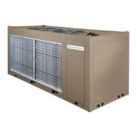
Air-Cooled Scroll Compressor Condensing Units
Brand:
Quantech
| Category:
Heat Pump
| Size: 10.68 MB
Table of Contents
Table of Contents
5
Section 1 - General Equipment Information and Safety
9
Introduction
9
Compressors
9
Condenser
9
Refrigerant Circuit
9
Warranty
9
Safety and Quality
10
About this Manual
10
Misuse of Equipment
10
Section 2 - Product Description
13
Introduction
13
General System Description
13
FIGURE 1 - Quantech Air-Cooled Scroll Compressor Condensing Unit
13
Microcomputer Control Center
14
Building Automation System Interface
15
Communications
15
Power Panel
15
Accessories and Options
16
Discharge Pressure Transducers and Readout Capability
16
FIGURE 2 - Unit Components Front
18
FIGURE 3 - Power Panel Components
19
FIGURE 4 - Power Panel / Control Components
20
Basic Unit
21
FIGURE 5 - Refrigerant Flow Diagram
25
FIGURE 6 - Process and Instrumentation Diagram
26
Section 3 - Handling and Storage
27
Delivery and Storage
27
Inspection
27
Unit Rigging
27
FIGURE 7 - Unit Rigging
27
Section 4 - Installation
29
Installation Checklist
29
Handling
29
Location and Clearances
29
Spring Isolators (Optional)
30
Compressor Mounting
30
Pipework Arrangement
30
Ductwork Connection
30
Recommendations of the Building Services Research Association
30
Wiring
30
High Pressure Cutout
32
Compressor Heaters
32
Refrigerant Piping
32
TABLE 1 - Fitting Equivalent Lengths
33
TABLE 2 - Refrigerant Piping Charges
33
TABLE 3 - Miscellaneous Liquid Line Pressure Drops
34
TABLE 4 - Refrigerant Line Connections
34
Oil Traps
35
Refrigerant Charge
35
Refrigerant Piping Reference
35
Filter Driers / Sight Glasses/ Txv's
35
FIGURE 8 - Single-Point Supply Connection - Terminal Block, Non-Fused Disconnect Switch
36
FIGURE 9 - Discharge Air Sensor Field Wiring
36
FIGURE 10 - Control Wiring
37
Section 5 - Technical Data
39
TABLE 5 - Voltage Limitations
39
TABLE 6 - Physical Data (English)
40
TABLE 7 - Micro Panel Power Supply
41
TABLE 8 - Voltage Range
41
TABLE 9 - Lug Ranges
45
FIGURE 11 - Control Wiring Diagram, Single Circuit, IPU II
51
FIGURE 12 - Control Wiring Diagram, Single Circuit, IPU II
53
FIGURE 13 - Control Wiring Diagram, Dual Circuit, IPU II
55
FIGURE 14 - Control Wiring Diagram, Dual Circuit, IPU II
57
FIGURE 15 - Control Wiring Diagram, Details, Single Circuit
58
FIGURE 16 - Control Wiring Diagram, Details, Dual Circuit
60
FIGURE 17 - Power Wiring, Single Circuit
62
FIGURE 18 - Power Wiring, Single Circuit
64
FIGURE 19 - Power Wiring, Single Circuit
66
FIGURE 20 - Power Wiring, Single Circuit
68
FIGURE 21 - Power Wiring, Dual Circuit
70
FIGURE 22 - Power Wiring, Dual Circuit
72
FIGURE 23 - Connection Wiring, Single Circuit
74
FIGURE 24 - Connection Wiring, Single Circuit
76
FIGURE 25 - Connection Wiring, Single Circuit
78
FIGURE 26 - Connection Wiring, Single Circuit
80
FIGURE 27 - Connection Wiring, Dual Circuit
82
FIGURE 28 - Connection Wiring, Dual Circuit
84
FIGURE 29 - Unit Clearances - All Models
88
FIGURE 30 - Sample Isolator Location Drawing
89
FIGURE 31 - Isolator Locations, 60 HZ
90
FIGURE 32 - One Inch Deflection Spring Isolator Cross-Reference
91
FIGURE 33 - One Inch Deflection Spring Isolators Installation Instructions
92
FIGURE 34 - Two Inch Deflection Seismic Isolator Cross-Reference
93
FIGURE 35 - Seismic Isolator Installation and Adjustment
94
FIGURE 36 - Durulene Isolator Cross-Reference
95
FIGURE 37 - Installation of Durulene Vibration Isolators
96
Section 6 - Commissioning
97
Preparation - Power off
97
Preparation - Power on
98
Equipment Pre-Startup and Startup Checklist
99
Section 7 - Unit Controls
103
Introduction
103
Microprocessor Board
103
Unit Switch
104
Display
104
Keypad
104
Battery Backup
104
Transformer
104
Single System Select and Programming # of Compressors
104
TABLE 10 - Status Key Messages Quick Reference List
110
TABLE 11 - Operation Data
114
TABLE 12 - Cooling Setpoints Programmable Limits and Defaults
125
TABLE 13 - Program Key Limits and Defaults
125
TABLE 14 - Setpoints Quick Reference List
126
TABLE 15 - Options Key Programming Quick Reference List
132
Section 8 - Unit Operation
133
Capacity Control
133
Suction Pressure Limit Controls
133
Discharge Pressure Limit Controls
133
Discharge Air Temperature Control
133
FIGURE 38 - Discharge Air Temperature Control
134
TABLE 16 - Discharge Air Temperature Control for 5 and 6 Compressors (7 and 8 Steps)
134
TABLE 17 - Discharge Air Temperature Control for 4 Compressors (6 Steps)
134
Suction Pressure Control
135
FIGURE 39 - Suction Pressure Control
135
System Lead/Lag
136
Compressor Lead/Lag
136
Anti-Recycle Timer
136
Anti-Coincidence Timer
136
Evaporator Blower Control
136
Evaporator Heater Control
136
Pumpdown Control
136
FIGURE 40 - QCC2040C - QCC2070C Fan Location (Typical)
137
TABLE 18 - QCC2015C - QCC2070C Condenser Fan Control Using Outdoor Ambient Temperature and Discharge Pressure
137
TABLE 19 - QCC2040C - QCC2070C Condenser Fan Control Using Discharge Pressure Only
137
TABLE 20 - QCC2015C - QCC2070C Low Ambient Condenser Fan Control
138
TABLE 21 - QCC2015C - QCC2030C Low Ambient Condenser Fan Control
138
Load Limiting
139
Compressor Run Status
139
Alarm Status
139
TABLE 22 - Compressor Operation - Load Limiting
139
BAS/EMS Discharge Air Temperature Reset Using a Voltage or Current Signal
140
Section 9 - Service and Troubleshooting
141
Clearing History Buffers
141
Service Mode
141
Service Mode - Outputs
141
Service Mode - Condensing Unit Configuration
142
Service Mode - Analog and Digital Inputs
142
Control Inputs/Outputs
143
TABLE 23 - I/O Digital Inputs
143
TABLE 24 - I/O Digital Outputs
143
TABLE 25 - I/O Analog Inputs
143
TABLE 26 - I/O Analog Outputs
143
FIGURE 41 - Microboard Layout
144
Checking Inputs and Outputs
145
Table 27 - Outdoor Air Sensor Temperature/Voltage/Correlation
145
TABLE 28 - Discharge Air Temp. Sensor Temperature/Voltage/Resistance Correlation
146
TABLE 29 - Pressure Transducers
147
FIGURE 42 - I/O Board Relay Contact Architecture
148
Optional Printer Installation
149
FIGURE 43 - Printer to Microboard Electrical Connections
149
TABLE 30 - Troubleshooting
151
Section 10 - Maintenance
153
Important
153
Compressors
153
Condenser Fan Motors
153
Condenser Coils
153
Operating Parameters
153
Onboard Battery Backup
153
Overall Unit Inspection
153
Bacnet, Modbus and Yorktalk 2 Communications
154
FIGURE 44 - Micro Panel Connections
155
TABLE 31 - Minimum, Maximum and Default Values
155
TABLE 32 - Values Required for Bas Communication
156
TABLE 33 - Real Time Error Numbers
156
TABLE 34 - Bacnet and Modbus Communications Data Map
158
TABLE 35 - Yorktalk 2 Communications Data Map
162
Advertisement
Advertisement
Related Products
Quantech QCC2070CEE
Quantech QCC3
Quantech QTC3100THE
Quantech QTC2025T
Quantech QTC2035T
Quantech QTC40220
Quantech QTC40216
Quantech QTC40310
Quantech QTC40395
Quantech QTC3130T
Quantech Categories
Chiller
Air Compressor
Heat Pump
More Quantech Manuals
Login
Sign In
OR
Sign in with Facebook
Sign in with Google
Upload manual
Upload from disk
Upload from URL