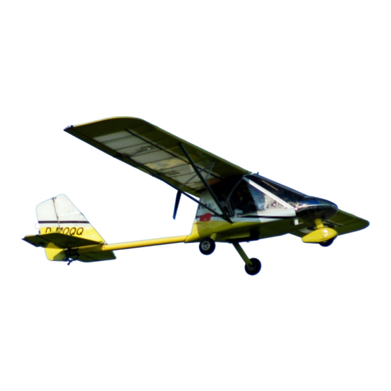
Rans S-12 Airaile Manual
Hide thumbs
Also See for S-12 Airaile:
- Quick start manual (3 pages) ,
- Pilot operating handbook (35 pages)

Related Manuals for Rans S-12 Airaile


Summary of Contents for Rans S-12 Airaile
- Page 29 01A-1 MAIN GEAR LEG ASSEMBLY Locate the parts shown in the parts manual The use of a “D” size drill bit should be followed as described in gear leg assembly. Due to the nature of the heat-treated gear legs it will be necessary to drill the gear legs to 1/4", while only drilling the sockets to “D”.
- Page 30 01A-2 FIGURE 01A-03A IMPORTANT: Fuselage must be in taxi position before setting main gear toe-in. Set up the gear to have exactly zero degrees of toe-in with the nose gear on the ground (skip forward and install the nose gear at this time, if you have not done so).
- Page 31 01A-3 FIGURE 01A-05 With the gear legs properly set, use the pre-drilled hole in the fuselage socket as a drill guide. Drill #11 from each side to mark each gear leg (Do NOT drill through). A 90º drill attachment will be required. Remove the gear leg and finish drilling from each side in a drill press.
- Page 32 01A-4 7 & 8 ALTERNATIVE METHOD: Remove the gear leg and finish drilling from each side in a drill press with a V- block. After drilling thru #11, drill out to 1/4". Step drill hole in the gear socket to 1/4”. Insert the gear leg back into the fuselage socket and align the holes.
- Page 33 01B-1 WHEEL AND HYDRAULIC BRAKE ASSEMBLY STANDARD & TUNDRA NOTE: If installing Main Gear Wheel Pants, refer to MAIN WHEEL PANT INSTALLATION, later in this section, before proceeding. Bolt caliper mount, fairing mount bracket and axle to the gear leg assembly as per parts drawing. Assemble the wheel and brake kit as per parts manual and manufacturers instructions.
- Page 34 01B-2 MAIN WHEEL PANT INSTALLATION HYDRAULIC BRAKES Press the Axle Extender into the axle until bottomed on the Axle Extender shoulder. Drill #30 through the extender using the pre-drilled axle holes as a guide. Complete Wheel and Brake assembly. Make a template as shown in Figure 01C-02 from poster board to mark the bottom hole for wheel clearance.
- Page 35 01B-3 Make a template out of poster board as shown in Figure 01C-03 for the brake cutout. The location of center should be 1/2" directly below the dimple on the wheel pant. Mark the wheel pant using the template. Remove the material using a fine blade jigsaw or Dremel with Reinfiorced Cut-off Wheel. BE SURE to make a right and a left wheel pant.
- Page 36 01B-4 FIGURE 01C-03 09x01bhb msw 10/01/2010...
- Page 319 14D-1 S-12XL OPTIONAL TAIL CABLE ASSEMBLY Select the parts shown in the parts manual. During final assembly of flaps to wing and rudder to vertical fin. Include the hummertangs as shown in FIGURE 14D-01. Bolt one end of the tail cables to the bent hummer tangs attached to the top rudder hinge.
Need help?
Do you have a question about the S-12 Airaile and is the answer not in the manual?
Questions and answers