Advertisement
T
S
OOL
TICK
1. Handling Recommendations
To enable development, the ToolStick Base Adapter and daughter cards are distributed without any protective
plastics. To prevent damage to the devices and/or the host PC, please take into consideration the following
recommendations when using the ToolStick:
Never connect or disconnect a daughter card to or from the ToolStick Base Adapter while the Base Adapter is
connected to a PC.
Always connect and disconnect the ToolStick from the PC by holding the large plastic connector.
Avoid directly touching any of the other components.
Manipulate mechanical devices on the daughter cards, such as potentiometers, with care to prevent the base
adapter or daughter card from accidentally dislodging from their socket.
Rev. 0.1 9/06
Arrow.com.
Downloaded from
D
A
EBUG
DAPTER
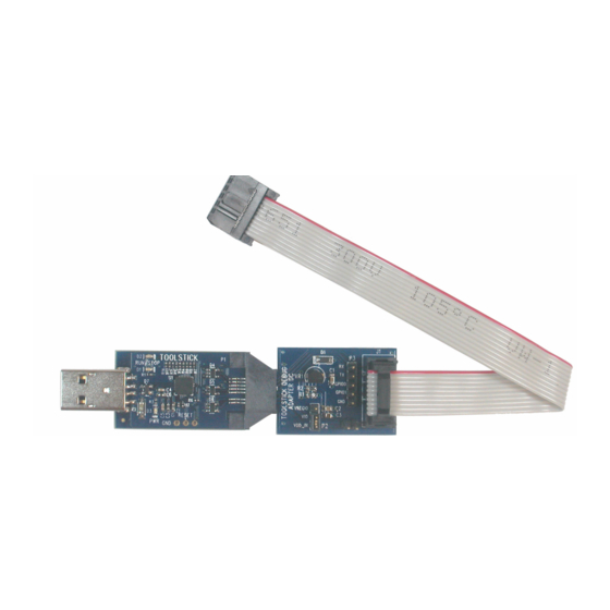
Figure 1. Proper Insertion
Figure 2. Improper Insertion
Copyright © 2006 by Silicon Laboratories
To o l Sti c k D e b u g A d a p t e r
U
'
G
S E R
S
U I D E
ToolStick Debug Adapter
Advertisement
Table of Contents

Subscribe to Our Youtube Channel
Related Manuals for Silicon Laboratories ToolStick Debug Adapter


Summary of Contents for Silicon Laboratories ToolStick Debug Adapter
- Page 1 Manipulate mechanical devices on the daughter cards, such as potentiometers, with care to prevent the base adapter or daughter card from accidentally dislodging from their socket. Rev. 0.1 9/06 Copyright © 2006 by Silicon Laboratories ToolStick Debug Adapter Arrow.com. Downloaded from...
- Page 2 Silicon Laboratories JTAG and C2 debug interfaces. Power is provided to the adapter from the USB connection to the PC. The ToolStick Debug Adapter is capable of providing power to a circuit board via pin 10 of the DEBUG connector. See the respective kit user’s guide for instructions on powering a target board from this source.
- Page 3 3. Connect one end of the USB cable to the USB connector on the ToolStick Debug Adapter. 4. Connect the other end of the USB cable to a USB port on the PC that will run the Silicon Laboratories IDE.
- Page 4 The Silicon Laboratories Integrated Development Environment (IDE), along with other software tools, are provided for device development and debugging. The IDE is available for download from the Silicon Laboratories website and is also available on microcontroller development kit CD-ROMs. Once the IDE has been installed and the hard- ware has been connected as shown in Section 4, follow the steps below to built a project, connect and download to a target board using the ToolStick Debug Adapter.
- Page 5 To olSt ick Debug Adapter 6. ToolStick Debug Adaper Schematic Rev. 0.1 Arrow.com. Arrow.com. Arrow.com. Arrow.com. Arrow.com. Downloaded from Downloaded from Downloaded from Downloaded from Downloaded from...
- Page 6 The products must not be used within any Life Support System without the specific written consent of Silicon Laboratories. A "Life Support System" is any product or system intended to support or sustain life and/or health, which, if it fails, can be reasonably expected to result in significant personal injury or death.
Need help?
Do you have a question about the ToolStick Debug Adapter and is the answer not in the manual?
Questions and answers