Table of Contents
Advertisement
Quick Links
8-B
USB D
I T
1. Introduction
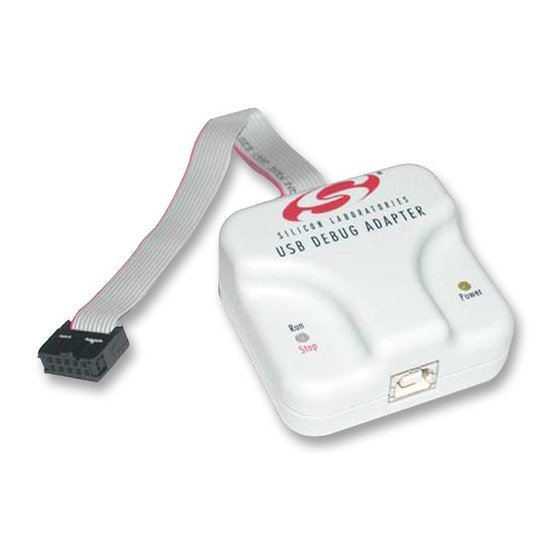
The 8-bit USB Debug Adapter (UDA) provides the interface between the PC's USB port and the Silicon Labs 8-bit
target device's in-system debug/programming circuitry. The 10-pin ribbon cable connects the adapter to the target
board and the target device's debug interface.
Visit
www.silabs.com/8bit-uda
2. Relevant Documentation
Application notes can be found on the 8-bit MCU Application Notes web page: www.silabs.com/appnotes.
AN124: Pin Sharing Techniques for the C2 Interface—Describes in detail the debug interface pin
sharing feature for C2 devices, which enables debugging and use of the /RST and GPIO pins shared with
C2CK and C2D.
AN117: Using C8051Fxxx On-Chip Interface Utilities DLL—The SiUtil DLL discussed in this document
uses the USB Debug Adapter to program the memory space of C2 and JTAG devices.
AN134: Multiple-Device JTAG Configuration in the Silicon Labs IDE—Configuration in the IDE and
using the USB Debug Adapter for devices in a JTAG chain.
Rev. 0.3 1/15
A
E B U G
DAPTER
Figure 1. 8-Bit USB Debug Adapter
for ordering information.
Copyright © 2015 by Silicon Laboratories
8-Bit USB Debug Adapter
U
'
G
SER
S
UIDE
8-Bit USB Debug Adapter
Advertisement
Table of Contents

Subscribe to Our Youtube Channel
Related Manuals for Silicon Laboratories 634-DEBUGADPTR1-USB


Summary of Contents for Silicon Laboratories 634-DEBUGADPTR1-USB
- Page 1 USB Debug Adapter to program the memory space of C2 and JTAG devices. AN134: Multiple-Device JTAG Configuration in the Silicon Labs IDE—Configuration in the IDE and using the USB Debug Adapter for devices in a JTAG chain. Rev. 0.3 1/15 Copyright © 2015 by Silicon Laboratories 8-Bit USB Debug Adapter...
- Page 2 3. Pinout Specification The 8-Bit USB Debug Adapter supports both Silicon Laboratories JTAG and C2 debug interfaces, and the adapter is powered from the USB connection to the PC. The UDA is also capable of providing power to the target device or other circuitry via pin 10 of the connector.
- Page 3 (pins 2, 3, or 9). 5. Hardware Setup using a USB Debug Adapter Connect a target board to a PC running the Silicon Laboratories IDE via the USB Debug Adapter as shown in Figure 3. 1. Connect the USB Debug Adapter’s 10-pin ribbon cable to the JTAG or Debug connector on the target board.
- Page 4 The Silicon Laboratories Integrated Development Environment (IDE) along with other software tools are provided for device development and debugging. The IDE is available for download from the Silicon Laboratories website (www.silabs.com/mcudownloads) and is also available on microcontroller development kit CD-ROMs.
- Page 5 8-Bit USB Debug Adapter 8. Schematics Rev. 0.3...
- Page 6 8-Bit USB Debug Adapter Rev. 0.3...
- Page 7 The products must not be used within any Life Support System without the specific written consent of Silicon Laboratories. A "Life Support System" is any product or system intended to support or sustain life and/or health, which, if it fails, can be reasonably expected to result in significant personal injury or death.
- Page 8 Mouser Electronics Authorized Distributor Click to View Pricing, Inventory, Delivery & Lifecycle Information: Silicon Laboratories DEBUGADPTR1-USB...
Need help?
Do you have a question about the 634-DEBUGADPTR1-USB and is the answer not in the manual?
Questions and answers