Ninglu AM706 Operation & Installation Manual
Anemometer
Hide thumbs
Also See for AM706:
- Operation & installation manual (46 pages) ,
- Operation & installation manual (16 pages)

Related Manuals for Ninglu AM706


Summary of Contents for Ninglu AM706
- Page 1 Anemometer AM706 Operation & Installation Manual Document: NLT-AM706C-SSEN Edition: V170701(EXP) Software: V1.3...
-
Page 2: Table Of Contents
Contents System description ............. 4 Main unit ............... 4 Sensor unit ..............4 Alarm unit ..............5 Peripheral equipment ............5 Printer ..............6 Repeater ..............6 System specification ............7 Physical ................ 7 Power ................8 Measurment ..............8 Functions .............. - Page 3 Installation ..............18 Main unit ..............18 Table mounting ............18 Flush mounting ............19 Sensor unit ..............20 Alarm unit (AM706A1) ............. 22 Wiring diagram ..22 Installation diagram Alarm unit (AM706A2) ............. 23 Installation diagram ..........23 Wiring diagram ............23 System diagrams ..............
-
Page 4: System Description
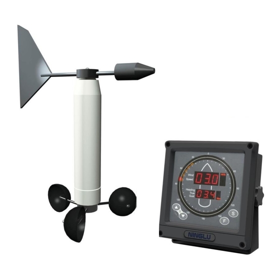
CCR alarm and deck alarm automatically give warnings when wind speed exceeds the setting value. The AM706 is consisted of 3 parts: Main unit, Sensor unit, Alarm units. Main unit The main unit AM706C receives the signal from the sensor unit, and displays: ... -
Page 5: Alarm Unit
System description Alarm unit AM706A1 is installed in the CCR (cargo control room). Light source: LEDs Light form: flash Light color: red Sound source: buzzer Sound form: continues AM706A1 Sound decibel: 60dB~85dB(A) AM706A2 is installed on the cargo deck Light source: Super bright LEDs Light form: rotating flash Light color: red Sound source: horn... -
Page 6: Printer
System description Printer Operating temperature: 0 ~ 40℃ Humidity: 30 ~ 80% RH Weight: 580 g Power: AC220/110V with adaptor DPU414 Current: 2A (Max) Lifetime: 500 thousand bite Printed mode: thermal serial dot-matrix Thermal record paper: CX-050B a roll of paper =30m 10 rolls/group 8 bite parallel /RS-232C serial Interface: Printed paper/content width: 112 mm/89.6 mm... -
Page 7: System Specification
System specification Physical Operating temperature: Main unit -15°C~+55°C Sensor unit -15°C~+70°C Alarm unit -15°C~+55°C Storage temperature: Main unit -20°C~+70°C Sensor unit -20°C~+85°C Alarm unit -20°C~+70°C Humidity: Main unit 10%-90% relative humidity Sensor unit 10%-100% relative humidity Alarm unit 10%-100% relative humidity IP degree Main unit IP 22... -
Page 8: Power
System specification Power Main display power supply: DC24V (20-32V) Wind sensor working power: DC9V to DC36V Power consumption: less than 10W (DC24V) AC adaptor: AC110/220V to DC24V Measurment The range of the wind speed: 1.2~25m/s The range of the wind direction: 0~359°... -
Page 9: Operation
Operation Sleep mode Press [▲] and [▼] at the same time, turn the main unit into sleep mode. Backlight Press [▲] or [▼] to set backlight of the main unit. Unit of the wind speed Press [S] on the main unit to inter the “wind speed unit selection”, then press [▲] or [▼] to select the speed unit. -
Page 10: Wind Speed Alarm Level
Operation Wind speed alarm level There are two levels alarm. If the wind speed achieves or exceeds the first level setting, the first level alarm is triggered with 1 form of sound/light. If the wind speed achieves or exceeds the second level setting, the second level alarm is triggered with 2 form of sound/light. -
Page 11: Set The Second Level Alarm Value
Operation Setting range: Turn the first level alarm off 3~ “X” m/s Step width: 1m/s 10~ “X” km/h Step width: 2km/h 5~ “X” knots Step width: 1kn Set the second level alarm value Press [F] three times on the display to enter the “2 level alarm setting”. -
Page 12: Alarm
Operation Alarm When wind speed achieves or exceeds the alarm setting value for 30 seconds, the main unit AM706C will sound an alarm and the letters in first LED line will be flashing; meanwhile, the main unit will send the alarm signal (switching value) to the alarm unit. -
Page 13: Printed Time Interval
Operation Printed time interval The printed time interval can be adjusted. Press [F] five times on the main unit to inter the “printed time interval setting mode”. The second line LEDs show the time interval, press [▲] or [▼] to select the interval time value. -
Page 14: Printer Setting
Operation Printer setting DPU-414 Print settings is showing as follow: Dip SW-1 1 (OFF):Input=Serial 2 (ON ):Printing Speed=High 3 (ON ):Auto Loading=ON 4 (OFF ):Auto LF=OFF 5 (ON ):Setting Command=Enable 6 (OFF):Printing 7 (ON ):Density 8 (ON ):=100% Dip SW-2 1 (OFF):Printing Columns=80 2 (ON ):User Font Back-up=ON 3 (ON ):Character Select=Normal... -
Page 15: Printed Format
Operation Printed Format With GPS input, printed format is showing as follow: 06/12/11 15:42 28°38.7010N(S) 121°25.8340E(W) 233° 11.0 Knot(s) ① ② ③ ④ ⑤ ⑥ (1) Date/month/year (2) Hour: minute (3) North Latitude (South Latitude) (4) East Longitude (West Longitude) (5) Wind direction (6) Wind speed Without GPS input, printed format is showing as follow:... -
Page 16: The Display Of The Second Line Leds
Operation After setting, press [F] again, the display of the LEDs on the main unit come back to normal situation. The display of the second line LEDs There are several cases about the display of the second line LEDs at the normal situation. -
Page 17: Calibration
Calibration... -
Page 18: Installation
Installation Main unit The main unit can be table or flush mounted. Table mounting Unit: mm... -
Page 19: Flush Mounting
Installation Flush mounting Flush mounting procedure 1. Make a cut out (169mmx169mm) in the Console. 2. Remove the mounting bracket. 3. Unscrew the 4 screws on the frame, then remove frame. 4. Put AM706C into the cut out, fix the inside 4 holes with self-tapping screws (ST4.2 ×... -
Page 20: Sensor Unit
Installation Sensor unit Put the wind vane at the top of the bracket, install as the following order: black O-ring, flat washer, spring washer, two nuts, cotter pin. The two nuts must be screwed tightly and cotter pin locked. Put the wind cups at the bottom of the bracket, then install as the following order: flat washer, spring washer, two nuts, cotter pin. - Page 21 Installation Ensure that the Sensor unit is mounted high enough to avoid any interference from obstacle. The fixed pillar/pipe diameter should be 60mm and make sure the activity radius 550mm. After the installation, calibration must be taken. Please refer to the “page P14”...
-
Page 22: Alarm Unit (Am706A1)
Installation Alarm unit (AM706A1) AM706A1 can be wall mounted with bracket supplied. Installation diagram Wiring diagram ATTENTION! The three lines of LIGHT, COMMON, SOUND will be damaged if connected to the AC220V power supply! High Voltage Hazard! High voltage is on LIGHT, COMMON, SOUND lines when alarm is connected with power. -
Page 23: Alarm Unit (Am706A2)
Alarm unit (AM706A2) AM706A2 can be installed on a console, panel, on the overhead, or on the bulkhead with tapping screws. Installation diagram Unit:mm Wiring diagram... -
Page 24: System Diagrams
System diagrams... -
Page 25: Wiring Diagram
Wiring diagram... -
Page 26: Supplementary Wiring For Printer Dpu-414
Supplementary wiring for printer DPU-414 Female RS232 of printer DPU-414 Male RS232 of printer cable Pin 3 → Print A → ③WC8 Pin 5 → Print B → ④WC9 Male RS232 of printer cable AM706C Supplementary wiring for repeater IR761 Pin 2 →...
Need help?
Do you have a question about the AM706 and is the answer not in the manual?
Questions and answers