Ninglu AM706 Operation & Installation Manual
Anemomete
Hide thumbs
Also See for AM706:
- Operation & installation manual (16 pages) ,
- Operation & installation manual (26 pages)

Related Manuals for Ninglu AM706


Summary of Contents for Ninglu AM706
- Page 1 Anemometer AM706 Operation & Installation Manual Document:NLT-AM706-SSCN Edition:V170816 Website:www.ninglutech.com...
-
Page 2: Table Of Contents
Contents Introduction ..............1 System Composition ................1 Function and Operation (AM706E) ....... 4 Display Layout ..................4 Function ....................4 Power on/off ..................4 Brightness..................4 OK ....................5 Day/Night Mode ................5 MODE ....................5 Arrow Keys ..................6 MENU .................... - Page 3 Normal display mode ................15 Set the dividing value of wind alarm ............. 16 Set the first level alarm value ..............17 Set the second level alarm value ............18 Gust mode .................... 19 Set GST mode ..................19 Printed time interval ................20 Specification ..............
- Page 4 Printer ................37 DPU-414 Specification ................37 Supplementary wiring for printer DPU-414 ........... 37 Printed Format ..................38 Printer setting ..................39 Repeater ............... 39 IR761 Specification ................40 Operation ....................40 Connection ................... 41 Appendix ..............42...
-
Page 5: Introduction
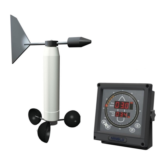
Introduction The Marine Anemometer AM706 is a combined instrument for wind speed and direction. It can measure relative wind speed (accuracy ±5%, min 0.1m/s), relative wind direction (digital display accuracy 1 ° , analog display accuracy 10 ° and output accuracy ± 1 ° ). GYRO (HDT) , SPEEDLOG (VBW)... - Page 6 Introduction Sensor unit AM706S The Sensor unit AM706S includes three parts: ·Wind speed sensor: A rotor with three wind cups. ·Wind direction sensor: A wind vane to drive an absolute angle sensor unit. ·Junction box: It has a waterproof junction box and a sensor unit transmitter.
- Page 7 Introduction Peripheral equipment Printer: DPU414, print date, wind speed & direction and so on Repeater: IR761, redisplay the wind speed & direction VDR: (vessel data recorder): record data from the main unit...
-
Page 8: Function And Operation (Am706E)
Function and Operation (AM706E) Display Layout Wind Speed Digital Display Wind Direction Analog Display Wind Direction Digital Display Operation Keyboard Power on/off Menu Mode Brightness Arrow keys Day/Night Mode Function Power on/off Press the on-off key to turn on /off the system. Brightness In Day/Night mode, press the brightness key to adjust the screen brightness. -
Page 9: Day/Night Mode
Function and Operation (AM706E) Press [OK] key to save the settings in the menu and return to the main screen. Day/Night Mode Press the Day/Night mode key to switch the day mode and night mode. MODE Press [MODE] key to select Relative Mode (relative speed + relative angle + max speed + average speed)... -
Page 10: Arrow Keys
Function and Operation (AM706E) Arrow Keys In the menu mode, press up/down arrow keys to select the setting items and press left/right arrow keys to select the setting values. MENU Menu Explanation Item Range Default Wind Alarm [Off 1~60m/s] Speed Unit [m/s km/h knots] Avg Time [1 min 2 min 5 min 10 min]... -
Page 11: Speed Unit
Function and Operation (AM706E) and flash. When the relative wind speed is less than the relative wind alarm value, the relative speed numbers return to white color and not flash. Then the system will be working normally. Press up/down arrow keys to select the item ‘Wind Alarm’ and press left/right arrow keys to set the wind alarm values. -
Page 12: Input Show
Function and Operation (AM706E) Input Show Set the input display of Gyro, Speedlog and GPS. Press up/down arrow keys to select the item ‘Input Show’ and press left/right arrow keys to select on and off. Setting Range is Off and On and default is Off. Language Set the system language. -
Page 13: Default
Function and Operation (AM706E) Default Reset the system. Setting Range is Off and Reset, and default is Off. Send Ture Set the transmitted relative or true sentence. Yes is to transmit relatvie and true sentence and No is to transmit relative sentence. Data transmission for NMEA0183 Main Unit Output --MWV $--MWV, x.x , a , x.x , a , A*hh<CR><LF>... -
Page 14: Gps Data Input--Rmc
Function and Operation (AM706E) GPS Data Input--RMC $--RMC, hhmmss.ss,A,llll.ll,a,yyyyy.yy,a,x.x,x.x,xxxxxx,x.x,a,a*hh<CR><LF> 8 9 10 1) UTC Time 2) Status, A=Data valid, V = Navigation receiver warning 3) Latitude,N or S 4) Longitude,E or W 5) Speed over ground, knots 6) Course Over Ground, degrees true 7) Date:ddmmyy 8) Magnetic Variation, degrees,E or W 9) Mode Indicator... -
Page 15: Speedlog Data Input--Vbw
Function and Operation (AM706E) Speedlog Data Input--VBW $--VBW, x.x , x.x , A , x.x , x.x , A , x.x , A , x.x , A*hh<CR><LF> 9 10 11 1) Longitudinal water speed, Knots 2) Transverse water speed, Knots 3) Status:water speed, A=data valid, V=data invalid 4) Longitudinal ground speed, Knots 5) Transverse ground speed, Knots... -
Page 16: Function And Operation (Am706C)
Function and Operation (AM706C) Display Layout Red outer ring: Relative wind direction Orange inner ring: Wind direction range Big digital tube: Current wind speed/mode Wind speed unit Small digital tube: See operation part Current mode display speed/mode Wind speed unit selection Mode selection Single press: Set brightness/ values Both Press: Inter sleep mode... -
Page 17: Input And Output
Function and Operation (AM706C) Input and Output RMC input baud rate: Automatic reception of 4800、 9600、 19200、 38400bps. Direction and speed output: 4800bps GPS input: NMEA0183-RMC (The data input cycle should not exceed 2 seconds) $--RMC, hhmmss.ss,A,llll.ll,a,yyyyy.yy,a,x.x,x.x,xxxxxx,x.x,a,a*hh<CR><LF> 8 9 10 1) UTC Time 2) Status, A=Data valid, V = Navigation receiver warning 3) Latitude,N or S... -
Page 18: About Nmea0183 Outputs
Function and Operation (AM706C) About NMEA0183 outputs The echo data outputs adopt NMEA0183 format complying with IEC61162-1. Data transmission: serial asynchronous mode, Baud rate 4800, 8 digits, no parity bit, 1 stop bit. Operation 〖 〗 Press [▲] and [▼] at the same time, turn the main unit Sleep mode into sleep mode. -
Page 19: Normal Display Mode
Function and Operation (AM706C) Normal display mode Red outer ring: Relative wind direction Orange inner ring: Wind direction range speed (relative) Big digital tube: Current wind Wind speed unit Small digital tube: max speed in measurement period Current mode display speed/mode Wind speed unit selection Mode selection... -
Page 20: Set The Dividing Value Of Wind Alarm
Function and Operation (AM706C) Set the dividing value of wind alarm Press [F] once on the main unit to enter the “wind alarm dividing value setting”. “dId” is flashing. The first line LEDs show “dId”, then press [▲] or [▼] to set the dividing value. -
Page 21: Set The First Level Alarm Value
Function and Operation (AM706C) Set the first level alarm value Press [F] twice on the main unit to enter the “1 level alarm setting”. “AL1” is flashing. The first line LEDs show “AL1”, then press [▲] or [▼] to set the value of the 1 level alarm. -
Page 22: Set The Second Level Alarm Value
Function and Operation (AM706C) Set the second level alarm value Press [F] three times on the display to enter the “2 level alarm setting”. “AL2” is flashing. The first line LEDs show “AL2”, then press [▲] or [▼] to set the value of the 2 level alarm. -
Page 23: Gust Mode
Function and Operation (AM706C) Gust mode When wind speed achieves or exceeds the alarm setting value for 30 seconds, the main unit AM706C will sound an alarm and the letters in first LED line will be flashing; meanwhile, the main unit will send the alarm signal (switching value) to the alarm unit. -
Page 24: Printed Time Interval
Function and Operation (AM706C) Printed time interval Press [F] five times on the main unit to inter the “printed time interval setting mode”. The second line LEDs show the time interval, press [▲] or [▼] to select the interval time value, from OFF / 15 s / 30s / 60s / 5min / 10min / 15min / 30min. -
Page 25: Specification
Specification Basic Specification Main Unit Dimension: W188mm H166mm D65 mm (AM706E) W202mm H196mm D64mm (AM706C) Weight: Main Unit 2kg+2kg Sensor 10kg Alarm unit 0.3kg (A1) + 3kg (A2) 24V DC (20-32V) Power Supply: Power through adapter: 110/220V 50/60Hz AC Power:... - Page 26 Specification Technical Specification Wind Speed Range: 0~60m/s Wind Speed Accuracy: ± 5%(min0.1m/s) Wind Direction Range: 0~359° Wind Direction Accuracy: ± 1° ≤ Min Start Speed: 1.2m/s...
-
Page 27: Maintenance
Maintenance Main Unit The main unit is maintenance-free. If doing the cleaning, use soft cloth and mild detergent, and avoid water drop. Sensor Part When there is ice or dirt on sensor to disturb the normal work, please clear in time. -
Page 28: Calibration
Calibration Calibration of AM706 wind vane after finishing the installation. -
Page 29: Installation
Installation Installation of Main Unit AM706E The Main unit AM706E has three mounting methods, table, hanging and flush mounting. The holder supplied by original factory setting is used in table and hung mounting. For flushing mounting, embed the main unit into the bridge control panel (the dimension is shown below) and tighten the rotary knob to fix the main unit. -
Page 30: Installation Of Main Unit Am706C
Installation Installation of Main Unit AM706C 1. Make a cut out (169mmx169mm) in the Console. 2. Remove the mounting bracket. 3. Unscrew the 4 screws on the frame, then remove frame. 4. Put AM706C into the cut out, fix the inside 4 holes with self-tapping screws (ST4.2 ×... -
Page 31: Installation Of Wind Sensor Am706S
Installation Installation of Wind sensor AM706S Wind Vane and Wind Cup Installation [ Wind Vane ] Wind vane is installed on the top of sensor holder, successively into black seal ring, plane washer, spring washer and 2 screw nuts. The two screw nuts should be tightened and then insert the cotter. [ Wind Cup ] Wind cup is installed on the bottom of sensor holder, successively into plane washer, spring washer and 2 screw nuts. -
Page 32: Integral Installation
Installation Integral Installation [ Space and location ] The total height of wind sensor is 838mm. It should be horizontally installed on the ventilated place of ship and the action radius of wind indicator and wind cup is over 550mm. Please note, big Radar antenna rotation can disturb the wind measurement. -
Page 33: 1St Alarm Unit(Am706A1
Installation 1st Alarm Unit(AM706A1) AM706A1 can be wall mounted with bracket supplied. Installation diagram Wiring diagram (unit:mm) YELLOW PURPLE GREY BLACK ATTENTION! The three lines of LIGHT, COMMON, SOUND will be damaged if connected to the AC220V power supply! High Voltage Hazard! High voltage is on LIGHT, COMMON, SOUND lines when alarm is connected with power. -
Page 34: Nd Alarm Unit (Am706A2)
Installation Alarm unit (AM706A2) AM706A2 can be installed on a console, panel, on the overhead, or on the bulkhead with tapping screws. (unitmm) Protection Cover Fitting Hole Junction Box Entrance hole PG13.5 YELLOW ATTENTION! GREEN The three lines of BLUE LIGHT, COMMON, SOUND... -
Page 35: Wiring Explanation
Wiring Explanation System View... -
Page 36: Am706E Wiring Explanation
AM706E Wiring Explanation Wiring Diagram of AM706E Back Cover... -
Page 37: System External Wiring Diagram Of Am706E
AM706E Wiring Explanation System External Wiring Diagram of AM706E... -
Page 38: Am706C Wiring Explanation
AM706C Wiring Explanation System External Wiring Diagram of AM706C The above colors are the colors of the cables provided by our company in the packaging accessories, which are two-core power cable, four-core sensor cable and seven-core data cable, respectively. -
Page 39: Connection Of Am706C And Am706S
AM706C Wiring Explanation The cables in the company's accessories are only for the convenience of the customer connection. The customer can be extended according to the installation needs. Connection of AM706C and AM706S AM706S Sensor Wirings junction box One four-core cable is used to connect the sensor to the main unit. -
Page 40: Connection Of 1
AM706C Wiring Explanation Connection of 1 alarm unit AM706A1 Wirings Three wirings of 1 alarm unit are directly connected to the alarm distributor. RED LIGHT →Distributor A1 LIGHT YELLOW COMMON→Distributor A1 COM PURPLE SOUND →Distributor A1 SOUND Two power wirings (grey and black) of 1 alarm unit are directly connected to AC220V/110V. -
Page 41: Printer
Printer DPU-414 Specification 0 ~ 40℃ Operating temperature: 30 ~ 80% RH Humidity: Weight: 580 g Power: AC220/110V with adaptor DPU414 Current: 2A (Max) Lifetime: 500 thousand bite Printed mode: thermal serial dot-matrix Thermal record paper: CX-050B a roll of paper =30m 10 rolls/group Interface: 8 bite parallel /RS-232C serial Printed paper/content width: 112 mm/89.6 mm... -
Page 42: Printed Format
Printer Printed Format With GPS input, printed format is showing as follow: 06/12/11 15:42 28° 38.7010N(S) 121° 25.8340E(W) 233° 11.0 Knot(s) ① ② ③ ④ ⑤ ⑥ (1) Date/month/year (2) Hour: minute (3) North Latitude (South Latitude) (4) East Longitude (West Longitude) (5) Wind direction (6) Wind speed Without GPS input, printed format is showing as follow:... -
Page 43: Printer Setting
Printer Printer setting Dip SW-1 1 (OFF):Input=Serial 2 (ON ):Printing Speed=High 3 (ON ):Auto Loading=ON 4 (OFF ):Auto LF=OFF 5 (ON ):Setting Command=Enable 6 (OFF):Printing 7 (ON ):Density 8 (ON ):=100% Dip SW-2 1 (OFF):Printing Columns=80 2 (ON ):User Font Back-up=ON 3 (ON ):Character Select=Normal 4 (ON ):Zero=Normal 5 (ON ):International... -
Page 44: Ir761 Specification
It receives NMEA0183 signal from a marine anemometer (talker), display the average, max/min wind speed on digit LEDs, and wind direction on a double LED circle. It’s 144x144 Din size cabinet is suitable for table, hanging and flush mounting. The installation is the same with AM706C. IR761 Specification 0 ~... -
Page 45: Connection
Repeater Connection COLOR SIGNAL COLOR SIGNAL 1 RED NMEA IN B 6 GREEN DIM- 2 BLACK NMEA IN A 7 YELLOW DIMKEY 3 BLUE NMEA OUT A 8 GREY SHIELD 4 WHITE NMEA OUT B DIM+ to DIM930 5 ORANGE DIM+ DIM- Brightness controller DIMKEY... -
Page 46: Appendix
Appendix Wind Grade Table Grade Speed(m/s) Speed(km/h) Grade Speed(m/s) Speed(km/h) 0.0~0.2 <1 24.5~28.4 89~102 0.3~1.5 28.5~32.6 103~117 1.6~3.3 6~11 32.7~36.9 118~133 3.4~5.4 12~19 37.0~41.4 134~149 5.5~7.9 20~28 41.5~46.1 150~166 8.0~10.7 29~38 46.2~50.9 167~183 10.8~13.8 39~49 51.0~56.0 184~20 13.9~17.1 50~61 56.1~61.2 202~220 ≥61.3 ≥221...
Need help?
Do you have a question about the AM706 and is the answer not in the manual?
Questions and answers
How to calibrate Ninglu AM706, it' s showing 10 time more speed. What's "=12Grate wind"