Ninglu AM706 Operation & Installation Manual
Anemometer
Hide thumbs
Also See for AM706:
- Operation & installation manual (46 pages) ,
- Operation & installation manual (26 pages)

Related Manuals for Ninglu AM706


Summary of Contents for Ninglu AM706
- Page 1 Anemometer AM706 Operation & Installation Manual Document: NLT-AM706-SSEN Edition: V120619 Website:www. ninglutech.com...
- Page 2 Quick operating guide Power drops alarm There will be an alarm when one of the power supplies drops off. Press any key to mute the alarm. [ F ] key Select display mode: Heading mode True wind mode Gust mode ...
-
Page 3: Table Of Contents
Operation ................ 5 Specifications ..............6 Maintenance ..............7 Calibration ..............8 Installation ..............9 Operator unit ..............9 Power adapter ..............9 Sensor unit ..............10 Junction ................ 12 AM706 system diagrams ..........12 AM706 main unit wiring diagram ........13... -
Page 4: Quick Operating Guide
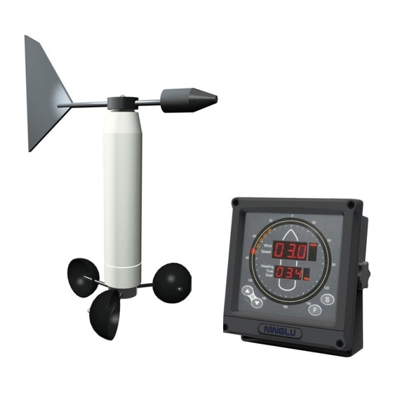
Introduction The Marine Anemometer AM706 is a combined instrument for wind speed and wind direction. It can measure relative wind speed (accuracy ±5%), relative wind direction (display accuracy 10 ° , output accuracy ± 1 ° ). With inputting GPS (RMC) data, user can choose heading, true wind, or gust mode. -
Page 5: Theory Description
Instruction Theory description The wind speed sensor has a rotor with three wind cups which spins as the wind moves past the boat. The Wind speed sensor measures how fast the rotor is spinning to calculate the wind speed. The wind direction sensor has a wind vane which points in the direction that the wind is coming from. -
Page 6: Function
Function Alarm Form explain Shows “ERR” when the operator unit receives no signal or the signal is not a NMEA message. Error alarm Shows “_ _ _” when the message is incorrect Shows “….” when receiving other message Power drops alarm Shows PL and buzzer warns when one of the power supplies drops Press any key to mute the alarm... -
Page 7: Nmea0183 Format
NMEA0183 format Output from AM706 to other marine equipments: $--MWV,x.x,a,x.x,a,A*hh<CR><LF> 1) Wind Angle, 0 to 360 degrees 2) Reference, R = Relative, T = True 3) Wind Speed 4) Wind Speed Unit, K/M/N 5) Status, A = Data Valid 6) Checksum Input from GPS or NMEA912 to AM706: $--RMC,hhmmss.ss,A,llll.ll,a,yyyyy.yy,a,x.x,x.x,xxxx,x.x,a*hh<CR><LF>... -
Page 8: Operation
Operation Turn on/off Press any key to turn on. Press ▲ ▼ at the same time to turn off. Press ▲ or ▼ to set backlight for display Set backlight Select wind speed unit Press [ S ] to select the wind speed unit:(m/s, knots, km/h, mph). Choose display mode Press [ F ] to select the display mode : Heading mode shows H(Chart 1) -
Page 9: Specifications
Specifications Dimension: W 196 x H202 x D 64mm Cutting window: W169 x H169mm Weight: Operator unit 2kg, Sensor unit 10 kg Main/Emergency power supply: 24VDC (20-32V) Main power can connect to 110/220V 50/60Hz AC through an adaptor Power consumption: less than 5W (24 VDC) Sensor unit measurement: Height 838mm, activity radius 550m... -
Page 10: Maintenance
Do not allow water to leak into the unit. Sensor unit Check the sensor unit, installation bolts and cable periodically. If the bracket of sensor unit is moved, please calibrate again. (Please refer to the CALIBRATION page P8 for detail). Please contact NINGLU local dealer for after-sales service. -
Page 11: Calibration
Calibration... -
Page 12: Installation
Operator unit The unit can be mounted on panel, table, wall or ceiling. 1. For table, wall or ceiling mounting use the supplied bracket from NINGLU. 2. For panel flush mounting, take off the bracket and the front frame. Cut a 169x169mm size square window in the panel, fix the inside 4 holes with self-tapping screws, and put on the front frame again. -
Page 13: Sensor Unit
Installation Sensor unit Wind vane and wind cups assembly Put the wind vane at the top of the bracket, install as the following order: black O-ring, flat washer, spring washer, two nuts, one cotter pin. The two nuts must be screwed tightly and cotter pin locked. Put the wind cups at the bottom of the bracket, then install as the following order: flat washer, spring washer, two nuts, one cotter pin. - Page 14 Installation Sensor unit installation Ensure that the sensor unit is mounted high enough to avoid any interference from obstacle. The fixed pillar/pipe diameter should be 60mm and make sure the activity radius 550mm. After the installation of operator unit and sensor unit, calibration must be taken.
-
Page 15: Junction
Junction AM706 system diagrams... -
Page 16: Am706 Main Unit Wiring Diagram
Junction AM706 main unit wiring diagram...
Need help?
Do you have a question about the AM706 and is the answer not in the manual?
Questions and answers