
Related Manuals for Siemens BC8001A


Summary of Contents for Siemens BC8001A
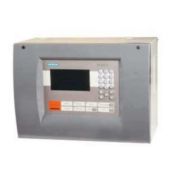
- Page 1 Installation and Operating Instruction Model BC8001A Building Technologies Fire Safety & Security Products...
-
Page 2: Table Of Contents
BC8001A Installation and Operating Instruction TABLE OF CONTENTS CHAPTER 1 DESCRIPTION ································································ 3 Introduction of BC8001A System ················································································· 3 Performance Parameters ···························································································· 4 BC8001A External Structure ························································································ 4 BC8001A Internal Structure ························································································· 5 Compatible Devices Table ··························································································· 5 CHAPTER 2 INSTALLATION ······························································· 6 Introduction ···············································································································... - Page 3 BC8001A Installation and Operating Instruction 11.2 How to isolate/open ··································································································· 26 11.3 How to activate/de-activate ·························································································· 28 11.4 How to test/walk-test ·································································································· 29 Configure ················································································································ 31 12.1 How to configure system ····························································································· 31 12.2 How to configure station ······························································································ 32 12.3...
-
Page 4: Chapter 1 Description
BC8001A Installation and Operating Instruction CHAPTER 1 DESCRIPTION Introduction of BC8001A System − Comply with UL864 − Compatible with BDS A series of field devices − 2-wire detection-bus (polarity-free), allowing transmission distances up to 1’000m (@ twisted pair 18 AWG) −... -
Page 5: Performance Parameters
BC8001A Installation and Operating Instruction Performance Parameters Items Standard Extension Configurations Configurations Number of detector lines (polarity free) Number of field devices LCD display 240×128 pixel, back light Nr. of monitored OC output (400 to 2K ohms @24VDC) Digital I/O’s Nr. -
Page 6: Bc8001A Internal Structure
BC8001A Installation and Operating Instruction BC8001A Internal Structure Compatible Devices Table Type Description Remark Standard BDS031A Addressable heat detector UL listed UL521 BDS051A Addressable smoke detector UL listed UL268 BDS121A Manual signaling box UL listed UL38 BDS132A Input module UL listed... -
Page 7: Chapter 2 Installation
6. Place the BC8001A over the four screws on the wall and slide it down on the screws. 7. Pull cable into the BC8001A control unit. Do not fix the wiring until the location of all the equipment is known. -
Page 8: Wiring
BC8001A Installation and Operating Instruction Figure 1 Mounting holes for BC8001A Wiring Install the wirings to the proper location. Refer to figure 2,3,4. Note: 1. All wirings must be in accordance with corresponding local code or regulation. 2. All wires are UL recognized. - Page 9 BC8001A Installation and Operating Instruction Figure 2 Internal wirings Page 8/49...
- Page 10 BC8001A Installation and Operating Instruction 120/240VAC N GND 12VDC*2 BAT+ BCB8004 Power supply BAT- 24V+I 24V- I 24V+II 24V-II 24V+ 24V- 24V+ 24V- BC8001A Main board 24VDC 24VDC@1.5A To Field Devices 400-2000ohm Figure 3 System Wiring Diagram Terminal description Name(label)
- Page 11 Line impedance: Max. 50ohm Figure 4 External wiring diagram No Connection A-Bus No Connection No Connection B-Bus No Connection To field devices Class B Style 4 24VDC@250mA,Supervised Power Limited Line impedance: max. 50ohm Figure 5 BC8001A Extension card wiring diagram Page 10/49...
-
Page 12: Power Supply
BC8001A Installation and Operating Instruction Power Supply Model: BCB8004 Features: Universal AC power input 120/240VAC,60/50Hz Alternative AC power switch Two power outputs of 24VDC AC fuse capacity: 5.0A; Battery fuse capacity: 10.0A 24V+I 120V 24V-I BCB8004... -
Page 13: Battery
BC8001A Installation and Operating Instruction Battery Wiring as refer to figure 6. Maximum battery circuit Charging: 3.1A Power Supply current Discharging:6A Capacity Sealed Leaded Bat- Bat+ Acid,12VDC,12Ah×2 Expected battery standby 24 Hours and 5 Minutes alarm operational times Dimension(mm) 181×76×167(L×W×H) Battery Maintenance Check battery regularly, if the following things happen, eg. -
Page 14: Chapter 3 Operation
Main menu function ⑦ LCD screen display ⑧ LEDs: Fire Alarm, Trouble, CPU Trouble, Power, Activation, Acknowledge, Alarm Silence, Reset ⑨ Buzzer: BC8001A has 4 kinds of sounds, which are used to indicate fire, trouble, isolation and active. ⑩ Page 13/49... -
Page 15: User Level
BC8001A Installation and Operating Instruction User level BC8001A includes three kinds of user levels: Level 1, Level 2 and Level 3 (as shown with red <Main Menu> L 1 A round). 1.RT Information Level 1 is default for everyone. ... -
Page 16: How To Login
BC8001A Installation and Operating Instruction How to login Press “ ” to enter main menu. <Main Menu> L 1 A The main menu is displayed. 1.RT Information 2.Set LCD Contrast 3. Log in 4. About Press “↓” to choose “Log in” and press “OK” key. -
Page 17: System Hierarchy
BC8001A Installation and Operating Instruction System Hierarchy Devices are organized in a hierarchy way: station - line - point. BC8001A Station Line BC8001A Port BC8001A BDS Line 2 Main IOs BDS Line1 (reserved) Power (Optional) Dry Contact Alarm BDS031A Heat... -
Page 18: Type Of Information
BC8001A Installation and Operating Instruction Type of Information BC8001A includes 6 types of information: Type of information Priority Fire Alarm Trouble Isolation Activation Test Walk-test How to query real time information: Press “ ” to enter main menu. <Main Menu> L 1 A The main menu is displayed. -
Page 19: Normal Status
2005-8-30 14:34:58 Note: “L1” displayed in the upper right corner of screen represents user level. BC8001A Normal screen control unit has totally three user levels, which are L1, L2 and L3. “A” represents control unit working in auto mode, and “M” represents control unit working in manual mode (The mode can be chosen via operating menu on panel). -
Page 20: Fire Alarm Event Handling
BC8001A Installation and Operating Instruction Fire Alarm Event Handling Status: <RT – Alarm:1> L1 A LCD will display fire event automatically as “Fire alarm screen”. * 1 Room 102 heat detector The red fire alarm LED is on. ... -
Page 21: Trouble Event Handling
If you can not remove the trouble by yourself, please call your local service office of Siemens Building Technologies. But if a trouble event is acknowledged and it is not removed within 24 hours, the buzzer will release trouble sound again but the current window on controller will remain unchanged and no new event is displayed. - Page 22 When application software crash or CPU hardware is damaged, system can not work normally and CPU trouble LED is on. Any key is not available. Now you have to switch off power and call for service from Siemens Building Technologies. Page 21/49...
-
Page 23: Isolation Event Handling
BC8001A Installation and Operating Instruction Isolation Event Handling Status: LCD will display isolation event automatically as “Isolation Screen”. <RT – Isolation:1> L1 A The isolation LED is on. - 1 Room 102 heat detector Acknowledge LED is flashing. -
Page 24: History Record
BC8001A Installation and Operating Instruction 10. History Record This function can be done by level 2/3 user. If current level is 1, login should be done first (Refer to “login” on page 14) and then follow these steps: How to query history record: Press “... -
Page 25: Operation
BC8001A Installation and Operating Instruction 11. Operation This function can be done by level 2/3 user. If current level is 1, login should be done first (Refer to “login” on page 14). Device Type Operation Item Isolate/ Activate/ Test/ WalkTest/... -
Page 26: How To Do System Test
BC8001A Installation and Operating Instruction 11.1 How to do system test Function: check work status of LCD, buzzer, LEDs. How to do: <Main Menu> L 3 A Press “ ” to enter main menu. 1. RT Information The main menu is displayed. -
Page 27: How To Isolate/Open
BC8001A Installation and Operating Instruction 11.2 How to isolate/open Isolate/Open Line Function: This is only necessary in exceptional situations, for example, while some part of the construction is in process. As soon as conditions have returned to normal, the isolated <RT –... - Page 28 BC8001A Installation and Operating Instruction Isolate/Open Point Function: only when it is damaged or defective until it is replaced. An isolated point can not generate any messages. As soon as replacement is finished, the isolated point must be immediately restored to normal status again.
-
Page 29: How To Activate/De-Activate
BC8001A Installation and Operating Instruction 11.3 How to activate/de-activate Function: To activate/de-activate OC, Output module manually from control unit. <RT – Active:1> L1 A Status: - 1 Floor 02 BDS221(A) Outpu LCD will display active event automatically as “Activation Screen”. -
Page 30: How To Test/Walk-Test
BC8001A Installation and Operating Instruction 11.4 How to test/walk-test Function: Allow to test the correct function of alarm devices. At test/walk-test mode alarm can be normally generated if alarm condition is fulfilled. But alarm devices are not really <RT – Test:1>... - Page 31 BC8001A Installation and Operating Instruction Press “↓” to choose one desired point and press “OK” key. <Operate Points > L3 A Isolate Open Test Walk-test Press “↓” to choose “Test” / ”Walk-test” and press “OK” key. Test status is shown.
-
Page 32: Configure
BC8001A Installation and Operating Instruction 12. Configure Functions: Configure system, including property and parameters of station, loops and field devices, showing interlock relationship, set system date & time, set LCD contrast, set volume of buzzer, set LCD switch off time, set language, automap, save configuration etc. -
Page 33: How To Configure Station
BC8001A Installation and Operating Instruction 12.2 How to configure station Press “ ” to enter main menu. <Main Menu> L 3 A The main menu is displayed. 1. RT Information 2. History Record 3. Operation 4. Configure Press “↓” to choose “4.Configure” and press “OK” key. -
Page 34: How To Configure Line
BC8001A Installation and Operating Instruction 12.3 How to configure line 1~5 steps is the same as “how to configure station”. <Configure Station> L 3 A Press “↓” to choose “1.Lines” and press “OK” key. 1. Lines All lines are displayed. Press “↓” / ”↑” to scrow down/up. -
Page 35: How To Configure Point
BC8001A Installation and Operating Instruction 12.4 How to configure point 1~7 steps is the same as “how to configure line”. Press “↓” to choose “1.Points” and press “OK” key. <Config Line> L 3 A All points are displayed. Press “↓” / ”↑” to scrow down/up. - Page 36 BC8001A Installation and Operating Instruction Editable Parameters of Different Point Point Type Parameter Default Value Optional Value BDS051(A) Smoke Detector Sensitivity Standard 1: Low 2: Standard 3: High BDS221(A) Output Module Supervision Time: 30…600 Seconds Supervision time: Define the waiting-for-...
-
Page 37: How To Edit Logic Expression
BC8001A Installation and Operating Instruction 12.5 How to edit logic expression 1~9 steps is the same as “how to configure point”. 10. Press “↓” to choose “2.Logic Statement” and press “OK” key. <Config Point> L 3 A Logic expression window is displayed. - Page 38 BC8001A Installation and Operating Instruction • “+~+”,*~* : Both are valid abbreviations. It is not applicable to “[ ]N”; For example: 01.011.001+~+01.011.015=01.011.016, which means that in the 1st line of No.1 Line Card in No.1 Controller, alarm (action) by any of No.1 to No.15 Equipment will link to No.16 Equipment;...
-
Page 39: How To Set Time & Date
BC8001A Installation and Operating Instruction 12.6 How to set time & date Press “ ” to enter main menu. <Main Menu> L 3 A The main menu is displayed. 1. RT Information 2. History Record 3. Operation 4. Configure Press “↓” to choose “4.Configure” and press “OK” key. -
Page 40: How To Set Lcd Contrast
BC8001A Installation and Operating Instruction 12.7 How to set LCD contrast Press “ ” to enter main menu. <Main Menu> L 3 A The main menu is displayed. 1. RT Information 2. History Record 3. Operation 4. Configure Press “↓” to choose “4.Configure” and press “OK” key. -
Page 41: How To Set Buzzer Volume
BC8001A Installation and Operating Instruction 12.8 How to set buzzer volume Press “ ” to enter main menu. <Main Menu> L 3 A The main menu is displayed. 1. RT Information 2. History Record 3. Operation 4. Configure Press “↓” to choose “4.Configure” and press “OK” key. -
Page 42: How To Set Lcd Switch Off Time
BC8001A Installation and Operating Instruction 12.9 How to set LCD switch off time Function: If no key is pressed within a certain time, LCD turns off automatically. LCD can be lighted up by pressing any key. But if fire or faults happen, the LCD turns on immediately. -
Page 43: How To Set Language
BC8001A Installation and Operating Instruction 12.10 How to set Language Press “ ” to enter main menu. <Main Menu> L 3 A The main menu is displayed. 1. RT Information 2. History Record 3. Operation 4. Configure Press “↓” to choose “4.Configure” and press “OK” key. -
Page 44: How To Automap
BC8001A Installation and Operating Instruction 12.11 How to automap Function: Automap can find address of all field devices which are connected with control unit and list them as points. When you navigate points, for those points which are configured will remain unchanged and display its text content and for those points which are not configured will display with “?New?Automap”. -
Page 45: How To Save Configuration
BC8001A Installation and Operating Instruction 12.12 How to save configuration Function: To permanently save the modification of property and logic expression of system, station, line and point. Otherwise the modification will be lost when the system reset. Press “ ” to enter main menu. -
Page 46: Auto/Manual Mode
BC8001A Installation and Operating Instruction 13. Auto/Manual Mode Auto: The output modules will be activated automatically when their logic statements are fulfilled. Manual: The output modules will not be activated automatically when their logic statements are fulfilled. They need to be activated manually by user. -
Page 47: About
BC8001A Installation and Operating Instruction 14. About Function: To display system software version, license number and last download time. How to do: Press “ ” to enter main menu. <Main Menu> L 3 A The main menu is displayed. 1. RT Information 2. -
Page 48: Chapter 4 Maintenance
BC8001A Installation and Operating Instruction CHAPTER 4 MAINTENANCE Daily Checking Persons on duty should do daily check of control unit and make records. If fire alarm, troubles and other abnormal events happen, “Trouble-shooting Guideline” shall be followed. After the control unit restores to normal, the events shall be well recorded. - Page 49 BC8001A Installation and Operating Instruction Failure content Possible reasons Solutions Auto-interlocking trouble Interlocking relationship is not set Change configuration file; correctly or interlocking relationship is not right; Control device is damaged; Replace damaged equipment; Power supply or control line trouble;...
-
Page 50: Fuse Replacement
BC8001A Installation and Operating Instruction Fuse Replacement Name Model Replacement Battery fuse capacity Replace the same model product AC fuse capacity Replace the same model product For problems with other components, please contact manufacturer for replacement. Battery Maintenance Perform the following tests at the recommended interval. Replace the battery set every four years or if any of the test criteria are not met. - Page 51 © 2011 Copyright by Beijing Siemens Cerberus Electronics Limited No.1,Fengzhidonglu, Xibeiwang, HaiDian District, Beijing Siemens Cerberus Electronics Ltd. Beijing, 100094, China Data and design subject to change without notice. Tel: +10 6476 8806 Fax: +10 6476 8899 Doc. No. A5Q00016841A...
Need help?
Do you have a question about the BC8001A and is the answer not in the manual?
Questions and answers