
Subscribe to Our Youtube Channel
Related Manuals for Samson 2406


Summary of Contents for Samson 2406
- Page 1 EB 2522 EN Translation of original instructions Type 2406 Excess Pressure Valve Self-operated Pressure Regulators Edition October 2021...
- Page 2 Note on these mounting and operating instructions These mounting and operating instructions assist you in mounting and operating the device safely. The instructions are binding for handling SAMSON devices. The images shown in these instructions are for illustration purposes only. The actual product may vary.
-
Page 3: Table Of Contents
Contents Safety instructions and measures ..............4 Notes on possible severe personal injury ............7 Notes on possible personal injury ..............7 Notes on possible property damage ..............8 Markings on the device ................10 Regulator nameplate ..................10 2.2 Material identification number ..............10 Design and principle of operation ..............11 Technical data .....................13 Measures for preparation ................18 Unpacking ....................18... -
Page 4: Safety Instructions And Measures
Therefore, operators must ensure that the device is only used in operating conditions that meet the specifications used for sizing the device at the ordering stage. In case operators intend to use the device in other applications or conditions than specified, contact SAMSON. SAMSON does not assume any liability for damage resulting from the failure to use the de- vice for its intended purpose or for damage caused by external forces or any other external factors. Î Refer to the technical data and nameplate for limits and fields of application as well as possible uses. - Page 5 Safety instructions and measures Safety features The Type 2406 Regulator does not have any special safety features. When relieved of pres- sure, the regulator is closed by the force of the set point springs. Personal protective equipment We recommend checking the hazards posed by the process medium being used (e.g. u GESTIS (CLP) hazardous substances database). − Provide protective equipment (e.g. safety gloves, eye protection) appropriate for the pro- cess medium used.
- Page 6 Start-up and shutdown procedures fall within the scope of the operator's duties and, as such, are not part of these mounting and operating instructions. SAMSON is unable to make any statements about these procedures since the operative details (e.g. differential pressures and temperatures) vary in each individual case and are only known to the operator.
-
Page 7: Notes On Possible Severe Personal Injury
Safety instructions and measures 1.1 Notes on possible severe personal injury DANGER Risk of bursting in pressure equipment. Valves and pipelines are pressure equipment. Improper opening can lead to valve components bursting. Î Observe the maximum permissible pressure for valve and plant. Î Before starting any work on the valve, depressurize all plant sections affected as well as the valve. Î To prevent uncontrolled excess pressure, make sure that suitable overpressure pro- tection is installed on site in the plant section. Î... -
Page 8: Notes On Possible Property Damage
WARNING Damage to health relating to the REACH regulation. If a SAMSON device contains a substance which is listed as being a substance of very high concern on the candidate list of the REACH regulation, this circumstance is indi- cated on the SAMSON delivery note. - Page 9 Risk of regulator damage due to the use of unsuitable lubricants. The lubricants to be used depend on the regulator material. Unsuitable lubricants may corrode and damage surfaces. Î Only use lubricants approved by SAMSON. When in doubt, consult SAMSON. Risk of regulator damage due to the use of unsuitable tools.
-
Page 10: Markings On The Device
Markings on the device 2 Markings on the device 2.1 Regulator nameplate SAMSON 2009 xxxx Made in Germany Type designation (2406) Valve size Max. perm. operating pressure at the Pressure rating actuator p Permissible differential pressure (across Configuration ID the valve) Order number or date 10 Perm. temperature... -
Page 11: Design And Principle Of Operation
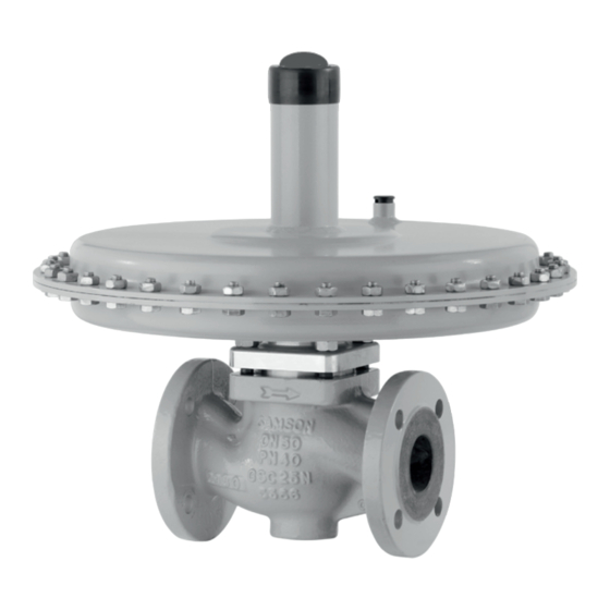
The upstream pressure p to be controlled is tapped upstream of the regulator and trans- In the version with pressure balancing, the mitted over an external control line to the forces produced by the upstream and down- Fig. 2: Type 2406 Excess Pressure Valve without pressure balancing EB 2522 EN... - Page 12 7 Set point spring 1 Valve body 8 Set point adjuster (screw SW 27) 2 Seat 3 Plug 9 Control line connection, G ¼ fitting 4 Plug stem 10 Balancing diaphragm Diaphragm plate with operating dia- Leakage line connection (special version), phragm G ¼ fitting 6 Actuator housing 12 Cap Fig. 3: Type 2406 Excess Pressure Valve with pressure balancing EB 2522 EN...
-
Page 13: Technical Data
Note − For gases The Type 2406 Regulator is not a safety − Temperature range from –20 to +60 °C valve. If necessary, a suitable overpressure protection must be installed on site in the − Set points from 5 mbar to 10 bar... - Page 14 Design and principle of operation Table 1: Technical data Valve size DN 15 DN 20 DN 25 DN 32, 40, 50 1) Pressure rating (valve) PN 16 · PN 25 · PN 40 Standard 0.1 · 0.25 · 0.4 · coefficients Reduced K 0.1 · 0.25 · 0.4 · 0.1 ·...
- Page 15 Design and principle of operation Table 2: Dimensions in mm Valve size DN 15 DN 20 DN 25 DN 32 DN 40 DN 50 Length L Forged steel – – Height H2 Other materials Without balancing Height H 5 to 15 mbar With balancing Actuator ØD = 490 mm, A = 1200 cm² Without balancing Height H With balancing 10 to 30 mbar ØD = 380 mm, ØD = 490 mm, Actuator A = 640 cm²...
- Page 16 150 mm min. 150 mm ØD ØD Control line connection G ¼, for A = 40, 80, Control line connection G ¼, for A = 640 and 160 and 320 cm² 1200 cm² The control line connection is turned by 90° in the drawing. The connection is normally located oppo- site the side with the arrow indicating the direction of flow. G ¼ fitting Control line connection at the side of the actuator Control line connection on the bottom of the housing actuator housing Fig. 4: Dimensions of Type 2406 EB 2522 EN...
- Page 17 Design and principle of operation Table 3: Weights in kg Valve size DN 15 DN 20 DN 25 DN 32 DN 40 DN 50 5 to 15 mbar 10 to 30 mbar 25 to 60 mbar 50 to 200 mbar 0.1 to 0.6 bar 0.2 to 1 bar 0.8 to 2.5 bar 2 to 5 bar 4.5 to 10 bar Body made of cast steel 1.0619: +10 % EB 2522 EN...
-
Page 18: Measures For Preparation
2. Check the shipment for transportation tached lifting equipment. damage. Report any damage to Do not attach lifting equipment to mounting SAMSON and the forwarding agent parts (e.g. adjusting screw or control line). (refer to delivery note). 4.1 Unpacking Transport instructions − Protect the device against external influ-... -
Page 19: Storage
− Observe the storage instructions. ing the pipelines in the plant. − Avoid long storage times. Contact SAMSON in case of different stor- Î Ensure that there is no liquid, e.g. con- age conditions or longer storage times. densed water, inside the regulator. If nec- essary, blow out the connecting parts with clean compressed air. -
Page 20: Mounting And Start-Up
Mounting and start-up 5 Mounting and start-up − Make sure the direction of flow matches the direction indicated by the arrow on the body. 5.1 Installing the valve into the − Install the regulator free of stress and pipeline with the least amount of vibrations as possible. -
Page 21: Mounting Orientation
Strainers Preferably install the regulator in a horizon- We recommend installing a strainer (e.g. tal pipeline. The actuator housing with set SAMSON Type 2 N) upstream of the regula- point adjuster must face upwards. tor. It prevents solid particles in the process medium from damaging the valve. Î Install the strainer upstream of the tem- Fig. 6:... - Page 22 Mounting and start-up Control line NOTICE Fitting with G ¼ female thread (9) on the ac- Regulator damage due to condensed water. tuator housing. Route the control line on site In applications in which the gas can liquefy, preferably using a 6 mm or ¼“ (stainless) condensate may form in the control line, steel pipe. causing damage to the regulator. To allow Always connect the control line connection condensate to run back into the tank, install for pressure tapping (see Fig. 5) directly to...
-
Page 23: Quick Check
Mounting and start-up 5.2 Quick check Adjusting screw Pressure test (8), SW 27 A pressure test of the plant with the regulator already installed is only permissible up to the nominal pressure of the valve (see Table 1). The pressure at the operating diaphragm must not exceed the maximum permissible pressure. If this cannot be guaranteed, pro- Fig. 10: Set point adjustment (view from above) ceed as follows: unscrew the control line at... - Page 24 Mounting and start-up The pressure gauge (Fig. 5) installed on the upstream side on site allows the adjusted set point to be monitored. EB 2522 EN...
-
Page 25: Servicing
− Before starting any work on the valve, de- Note pressurize all plant sections affected as The device was checked by SAMSON before well as the valve. it left the factory. − Drain the process medium from all the −... -
Page 26: Preparation For Return Shipment
Defective valves can be returned to Contact your nearest SAMSON subsidiary SAMSON for repair. or SAMSON's After-sales Service for infor- mation on spare parts, lubricants and tools. Proceed as follows to return devices to SAMSON: 1. Put the control valve out of operation (see section 8). -
Page 27: Malfunctions
Order no.: vibrations 1991-7114 for A =1200 or 640 cm² 1991-7113 for A =320 or 160 cm² Check the sizing data used for the reg- ulator. If necessary, change the K Improper sizing of the regulator. efficient, seat diameter or actuator ar- Note Contact SAMSON's After-sales Service for malfunctions not listed in the table. EB 2522 EN... -
Page 28: Decommissioning And Removal
Decommissioning and removal 8 Decommissioning and 8.1 Decommissioning removal To decommission the control valve for service and repair work or disassembly, proceed as follows: DANGER Risk of bursting in pressure equipment. 1. Close the shut-off valve on the upstream Valves and pipelines are pressure equip- side. -
Page 29: Annex
− EU Declaration of Conformity of Final E-mail address Machinery on page 31. You can reach our after-sales service at af- tersalesservice@samsongroup.com. Addresses of SAMSON AG and its subsid- iaries The addresses of SAMSON AG, its subsid- iaries, representatives and service facilities worldwide can be found on our website (www.samsongroup.com) or in all SAMSON product catalogs. - Page 30 45-4, 45-5, 45-6, 2468, 2478 (2720), 45-9, 46-5, 46-6, 46-7, 46-9, 47-1, 47-4, 47-5, 47-9, 2487, 2488, 2489, 2491, 2494, 2495 (2730), 2405, 2406, 2421 (2811), 2392, 2412 (2812), 2114 (2814), 2417 (2817), 2422 (2814), 2423 (2823) die Konformität mit nachfolgender Anforderung/the conformity with the following requirement.
- Page 31 EB 2522 EN...
- Page 32 EB 2522 EN SAMSON AKTIENGESELLSCHAFT Weismüllerstraße 3 · 60314 Frankfurt am Main, Germany Phone: +49 69 4009-0 · Fax: +49 69 4009-1507 samson@samsongroup.com · www.samsongroup.com...
Need help?
Do you have a question about the 2406 and is the answer not in the manual?
Questions and answers