Table of Contents
Advertisement
Quick Links
OPERATING AND MAINTENANCE
HIGH POWER TWT AMPLIFIER
Prepared for:
Prepared by:
INSTRUCTIONS
MODEL T251-500A
DOCUMENT NUMBER
T251-500A Rev.A
SERIAL NUMBER
Advanced Test Equipment
10401 Roselle St.
San Diego, CA 92121
Phone: 858-588-6500
S/O #
P/O #
Instruments for Industry
903 South Second Street
Ronkonkoma, NY 11779
Phone 631 467-8400
Fax
631 467-8558
Email info@ifi.com
Advertisement
Table of Contents

Subscribe to Our Youtube Channel
Related Manuals for ifi T251-500A


Summary of Contents for ifi T251-500A
- Page 1 OPERATING AND MAINTENANCE INSTRUCTIONS MODEL T251-500A HIGH POWER TWT AMPLIFIER DOCUMENT NUMBER T251-500A Rev.A SERIAL NUMBER Prepared for: Advanced Test Equipment S/O # 10401 Roselle St. P/O # San Diego, CA 92121 Phone: 858-588-6500 Prepared by: Instruments for Industry 903 South Second Street...
-
Page 2: Table Of Contents
TABLE OF CONTENTS SECTION DESCRIPTION PAGE INTRODUCTION ..........................3 GENERAL DESCRIPTION ........................ 4 WARRANTY INFORMATION ....................... 10 GENERAL INFORMATION Scope Of This Manual......................11 Operation Overview ......................11 General Specifications ......................12 Functional Description ......................12 Protection Circuits ....................... 13 Status Indicators, Controls and Connectors................. -
Page 3: Introduction
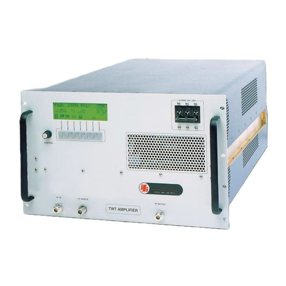
CONTENTS ( For a typical Wide Band Amplifier ) Quantity Description TWT High Power Wide Band Amplifier, P/N T251-500A Mating Connector, Power Line Operation and Instruction Manual Data Sheets (Included in Manual ) FIGURE 1.0 OUTLINE DRAWING Rev. -
Page 4: General Description
SECTION 2.0 GENERAL DESCRIPTION The Instruments For Industry, Inc. ( IFI ) manufactured TWT Wide Band Amplifier is a Bench Top or rack mount amplifier providing a nominal 500 Watts of RF power from 0.8 to 2.5GHz, with output power of at least 500 Watts. The minimum saturated output power midband of the operating frequency range is more than 500 Watts. -
Page 5: Front Display Panel Start Up Menu
TWTA Controller Operation A) Apply power to the unit using the front panel ON/OFF switch. Start. Figure 2.0, Front Panel Display – Start-Up Menu Start-Up Menu When the circuit breaker or AC power on switch is energized, the above menu will be displayed after the MPU booting cycle. -
Page 6: Front Display Panel Gpib Address Menu
Figure 3.0 Front Panel Display – GPIB address Menu The Start-up menu will be replaced by Operate menu after about 5 seconds. Rev. A 10/01/08... -
Page 7: Front Display Panel Operate Menu
Figure 4.0 Operate Menu Rev. A 10/01/08... -
Page 8: Front Display Panel Warm Up Time
Figure 5.0, Front Panel Showing Warmup time 1. Press the ON Key. The unit will display “FILAMENT WARMUP” and will start the countdown as set per TWT used. At this mode the Filament, Collector and Grid (if applicable) supplies will be energized. 2. -
Page 9: Front Display Panel Operate Mode With Rf Power Indication
Figure 6.0 Front Display Panel Showing Operate Mode with RF Power Indication 1. Place the unit in Operate (OPR) mode. At this mode the TWT will be turned ON. 2. The display will show the Helix and Collector, Voltages and Currents as per TWT operating data sheet (enclosed in the manual). -
Page 10: Warranty Information
This warranty is the full extent of obligation and liability assumed by IFI with respect to any and all IFI products. IFI neither makes, nor authorizes any person to make, any other guarantee or warranty concerning IFI Products. -
Page 11: General Information
SECTION 4.0 GENERAL INFORMATION 4.1 SCOPE OF THIS MANUAL This manual is intended to inform a qualified transmitter operator or technician of the normal operating and maintenance procedures for the TWT Amplifier. It is not intended to be a course of instruction for unqualified personnel. -
Page 12: General Specifications
4.4 GENERAL SPECIFICATIONS The specifications listed below represent the minimum performance characteristics at the time of delivery. SPECIFICATIONS Frequency Response 0.8 to 2.5 GHz (Functional) Rated Power Output: 500 Watts minimum 1.0-2.5GHz 250-500 Watts nominal increasing from 0.8-1.0GHz Power Gain: 57 dB, 1.0-2.5GHz Input Impedance: Nominal 50 Ohms... -
Page 13: Protection Circuits
4.6 PROTECTION CIRCUITS The TWT Amplifier is designed with a variety of protection circuits to provide safeguards for the amplifier should any adverse electrical conditions occur or if the amplifier accidentally experiences operator deviation of the design application. Listed below are the safeguards. 4.6.1 Overheat Protection The TWT, a critical component of this Amplifier, is mounted to a heat sink, which is in turn, air cooled by high efficiency blower. -
Page 14: Rear Panel Illustration
RF AMPLIFIER Front Panel: Rear Panel: POWER ON/OFF Ckt Bkr AC Source IEC Power Connector Local/Remote Switch IEEE-488, Connector Amp ON / OFF Switch RF Output, SC Female RF Input, N Female RF Sample, N Female Operate / Standby Switch Fault/Reset Switch Control Knob LCD Status Display... - Page 15 4.7.1 FRONT PANEL STATUS INDICATORS INDICATOR FUNCTION Fault LED The Fault LED illuminates when either the Helix or the Collector Power Supplies deviate from the design parameters. The Amplifier will revert to AMP OFF mode. It also illuminates when either a Thermal or Airflow condition occurs outside design parameters.
-
Page 16: Data Sheets
4.8 DATA SHEETS Provided with each Amplifier are specific Test Data Sheets measured from the amplifier using a calibrated 50 Ohm Pad to assist the operator in maximizing the performance of the Wide Band Amplifier. The accuracy of the Metering is ± .5 dB ( nominal ) so to provide the operator with the ability to maximize the performance of the wide band amplifier. -
Page 17: Principles Of Operation
IFI makes available with each shipped amplifier specific data and curves so the operator will know the proper input signal levels to more efficiently operate the amplifier, refer to Paragraph 4.7 herein. -
Page 18: Ieee-488 Interface Option
IEEE-488.2 Standard is implemented, which defines the protocols and syntax of commands. The GPIB command codes for the IFI Amplifier series are discussed on subsequent pages and, for ease of identification; the command codes are identified within the text by bold capital characters. -
Page 19: Ieee-488 Commands
IEEE COMMANDS FOR TWTA CODE TWTA FUNCTION AMP OFF AMP ON STBY Standby Operate OPRT RESET Fault Reset ATTUxx Increase Attenuation (xx- # of steps) [Response with Attenuator value](optional) ATTDxx Decrease Attenuation (xx- # of steps) [Response with Attenuator value](optional) REQUEST STATUS Code AMPLIFIER STATUS... - Page 20 REQUEST AMPLIFIER STATUS (POWER AND METERING) CODE TWTA FUNCTION Returns Forward Power Value POWERFWD POWERRFL Returns Reflected Power Value Returns Helix Volts Value HELIXV HELIXI Returns Helix Current Value COLLV Returns Collector Volts Value COLLI Returns Collector Current Value FILAMENTV Returns Filament Volts Value [ Optional ] Returns Grid Volts Value [ Optional ] GRIDV...
- Page 21 RS-232 Operation of Serial Port on RF Amplifier 1 – Connect serial port of amplifier to computer using a null modem cable or a standard serial cable with a null modem adapter. 2 – Use a program such as Hyperterm to communicate with the amplifier. (To reach “Hyperterm”...
-
Page 22: Maintenance And Servicing
SECTION 7.0 MAINTENANCE AND SERVICING 7.1 PERIODIC MAINTENANCE The only periodic maintenance required on the TWT amplifier system is insuring that the cooling vents are not obstructed in such a manner that the airflow is restricted. Periodic cleaning of the vents may be required depending on the degree of dust in the atmosphere. -
Page 23: Equipment Return Procedure
For this reason it is important to return the all the accessories with the equipment. It is also IFI's policy to verify performance of all associated accessories of Section 1.0 before returning the equipment to service. -
Page 24: Data Sheets
APPENDIX A TEST DATA SHEETS Rev. A 10/01/08... -
Page 25: Drawings
APPENDIX B Drawings Package T251-500A BILL OF MATERIALS (BOM) 900819 INTERCONNECT DIAGRAM 500466-4 TWT POWER/VSWR METERING BD. 500497-1 HALL EFFECT SENSOR CIRCUIT B 500499-1 SWITCH/LED BOARD ASSY 500503-2 MONITOR/FAULT BD ASSY 500511 PULSE MODULATOR BOARD ASSY 500521 GRID MODULATOR SERVICE SUPPL... - Page 26 BILL OF MATERIALS ITEM PART PRODUCT COST/ NO OF REV NUMBER DESCRIPTION SUBS LTR ITEM T261-500-6674 AMPLIFIER TWT, 1-2.8GHz, 500W CW, 230/400 3PH, 5 WIRE COMPONENTS Upper Level Component Part Extended Rev Unit Desg Part Number Part Number Description Req'd Cost Cost L evel Code T261-500-6674...
- Page 27 T261-500-6674 500553-2 COLLECTOR/HELIX RECTIFIER BD ASSY T261-500-6674 500558 PREAMP RELAY BD ASSY T261-500-6674 500563 FILAMENT SUPPLY BD ASSY, 7 AMP T261-500-6674 500563-2 PREAMP 15V 7A SUPPLY T261-500-6674 500567-2 2KW PWM ASSY WITH 302912 HTSK T261-500-6674 500584 PFC 3PH INPUT ASSY T261-500-6674 500585 PWM OVERCURRENT PROTECTION ASSY...
- Page 28 T261-500-6674 FIL-AYO1-20A FILTER, LINE, EMI,3 PHASE Y CONFIG. 250/440C VAC, 20A, 5 WIRE T261-500-6674 FLT-LA30F FILTER, LOWPASS, 3GHZ, 50W SMA T261-500-6674 FLT-LA30N FILTER, LOWPASS, 3GHZ, 50W T261-500-6674 HAN-245-31 HANDLE, BLK, 10-32 THREAD, 9.5" T261-500-6674 HDW-PLA-FTH-1 HDW, RICHO WIRE TIE HOLDER T261-500-6674 KNO-RKP3SB KNOB, SKIRTED, BLACK TEXTURE...
- Page 29 Helix Current Sample HV In INTERCONNECT DIAGRAM, TWTA A2P4-19 Helix Current Sense DRAWN BY Helix Ret R. GIBSON 9/12/07 Ground T251-500A, 230VAC CHECKED BY R. GIBSON 9/12/07 APPROVED BY HV Out R. GIBSON 9/12/07 SIZE CODE IDENT NO DRAWING NO...
- Page 30 VSWR FLT COM A2P4-14 RFL PWR MON A2P4-10 VSWR FLT OUT VSWR FLT +V PIN DIODE CTRL N.C. Title -12V -12V RF BLOCK DIAGRAM, T251-500A N.C. A2P4-13 FWD PWR MON Size Document Number R e v +12V +12V 900819-8145 Date:...
- Page 31 STAGE GA IN=5 APPROX 0.5V [R2 NOT USED] FOR FULL SCALE GAIN ADJ. 100K 100K S AT APPROX 2.5V INA321 INA321 R5 2K R6 2K FWD. DET. FWD _PWR (NEGATIVE VOLTA GE) -2.5V +2.5v 0.1uF 0.1uF 0.1uF GAIN ADJ. STAGE GA IN=5 100K APPROX 0.5V [R15 NOT USED]...
- Page 32 P/N LA55P +12V HALL-EFFECT SENSOR COLLECTOR -12V 5 TURNS OUTPUT 82, 1/2W 10uF,25V 0.01uF CON10,MOLEX 0.1 SPCING P/N LA55P +12V HALL-EFFECT SENSOR HELIX -12V 10 TURNS OUTPUT 82, 1/2W 10uF,25V 0.01uF INSTRUMENTS FOR INDUSTRY, INC. Title SCHEMATIC, HALL-EFFECT SENSOR CIRCUIT BD Size Document Number R e v...
- Page 33 INSTRUMENTS FOR INDUSTRY, INC.
- Page 34 PHLXI-MON (J5-7) PHLXI-FLT (J1-5) -12V 1N750 .1UF PHLXI-IN (J4-19) 100K,POT VQ100J HLX-I Cal .1UF .1UF LM124 LM124 LM124 -1.03V +2.44V +2.46V D1N4148 +1.67V LM124 +12V 10K,POT .1UF 510K RESET1 (PG3) D1N4148 Title SCHEMATIC, Monitoring Ckt BOARD , Helix PS current sense Size Document Number R e v...
- Page 35 HHLXI-FLT (J1-1) HHLXI-MON (J5-3) .1UF 1N750 -12V VQ100J .1UF LM124 LM124 HHLXI-IN (J4-15) LM124 D1N4148 LM124 100K,POT .1UF .1UF 510K +12V .1UF RESET2 (PG 4) D1N4148 10K,POT Title SCHEMATIC, Monitoring Ckt BOARD , HelixI sense - Hall effect Size Document Number R e v 500503-2 Date:...
- Page 36 HLXV-MON (J5-5) +12V -12V HLXV-FLT (J1-5) 100K,POT .1UF 1N750 HLX-V Cal VQ100J 10K,POT .1UF LM124 LM124 LM124 HLXV-IN (J4-20) +3.5V +0.72V +2.5V 100K D1N4148 6.8UF .1UF LM124 10K,POT U10D D1N4148 +1.5V VQ100J RESET (J1-20) D1N4148 RESET1 Title SCHEMATIC, Monitoring Ckt BOARD , Helix PS voltage sense Size Document Number R e v...
- Page 37 CATHV-MON (J5-4) +12V .1UF CATHV-FLT (J1-2) 1N750 -12V 100K,POT VQ100J 10K,POT .1UF LM124 LM124 CATHV-IN (J4-16) LM124 100K D1N4148 .1UF 6.8UF D1N4148 RESET2 LM124 RESET (J1-20) 10K,POT D1N4148 VQ100J Title SCHEMATIC, Monitoring Ckt BOARD , Cathode Volts sense Size Document Number R e v 500503-2 Date:...
- Page 38 COLLI-MON (JJ5--5) COLLI-FLT (J1-3) 1N750 .1UF R100 +5V NO FAULT -12V VQ100J +0.2V FAULT .1UF LM124 +0.010 TO 0.060V +1.0V LM124 COLLI-IN (J4-17) LM124 D1N4148 LM124 +2.5V -2.5V -10V NO FAULT 510K +2.6V .1UF .1UF +10V FAULT 100K,POT COLL-I CAL +12V .1uF RESET3...
- Page 39 COLLV-FLT (J1-4) COLLV-MON (J5-6) +12V -12V R101 1N750 .1UF 100K,POT VQ100J 10K,POT .1UF LM124 LM124 LM124 COLLV-IN (J4-18) +3.5V +0.74V +2.5V 100K D1N4148 6.8UF D1N4148 .1UF RESET3 LM124 RESET (J1-20) 10K,POT D1N4148 +1.5V VQ100J Title SCHEMATIC, Monitoring Ckt BOARD , Collector Voltage sense Size Document Number R e v...
- Page 40 R103 VQ100J VQ100J HLX-INHIBIT (J4-8) CON2 R102 HLX-ENABLE (J1-26) D23A MAD1108P R104 R105 D19B MAD1108P U10A D19C MAD1108P 74HC08 CATHV-FLT +24V .1UF D19D MAD1108P D1N4148 L293D U10B HHLXI-FLT RLY3-SOURCE RLY2-SOURCE D19E RLY1-SOURCE MAD1108P 74HC08 COLLV-FLT 1,2EN -12V 3,4EN D19F OPERATE (J1-28) MAD1108P R106 COLLI-FLT...
- Page 41 RFL-PWR FWD-PWR CATHV-MON HHLXI-MON COLLV-MON CATHV-FLT COLLI-MON HHLXI-FLT HLXV-MON COLLV-FLT PHLXI-MON COLLI-FLT GRIDV-IN HLXV-FLT FILV-IN PHLXI-FLT SPARE4 AIRFLOW SPARE3 VSWR INTERLOCK THERMAL PIN025DB SUMFLT-IN HEADER 7X2 PIN1DB PIN05DB PIN4DB PIN2DB PIN16DB PIN8DB RESET PIN32DB PULSE-OUT PULSE-IN RLY2-SINK SPARE1 RLY1-SINK SUMFLT-OUT PHLXI-FLT HLX-ENABLE RLY3-SINK...
- Page 42 10,1/2W 22uF 22uF Z15DICT 10, 2W MMBT3906 1N5384, 150V LL4148 BSS123 LL4148 1.2K LL4148 APT1003RBFLL 1.5uF, 400V 1N5384 BSS123 120K 1N5384 LL4148 LL4148 LL4148 300,1W 300,1W 300,1W 300,1W 300,1W 300,1W 22, 2W 22, 2W US1M 4.7K BSS123 US1M MMBT3906 US1M US1M GAP1 2.2K...
- Page 43 PART OF COPPER CLAD ASSEMBLY Z200DICT Z200DICT US1M ATP8060SVR GRID. 90V TO 130V TWT GRID 100, 1W US1M 10K,1W,SM 1MEG,1W,SM US1M US1M 120K,1W 120K,1W Z15DICT 4.7K,1/2W,SM Z47DICT 22UF,400V 22UF,400V POT, 20K 120K,1W FUSE, 0.25A 120K,1W Z100DICT BSS123 US1M US1M 100,1/2W,SM Z30DICT Z15DICT Z100DICT...
- Page 44 6.8UF,25V 22UF,35V 22UF,35V 22UF,35V US1M +15 VDC COMMON 15V 50/50 SQUARE WAVE SG3526DW REGULATION OUTA INHIBIT OUTB CURRENT SENSE COMP US1M R10 5.1K 0.1UF 2.2K CON10 VREF 3000PF R12 10K VOLT-ADJ. 5K,POT 4.7K CURRENT-ADJ. MMBT3906 BSS123 100UF,16V TL431CLP US1M US1M 2.7K 5K,POT 2.2K 1%...
- Page 45 51, 2W 51, 2W 3.15A 360VDC DC(+) APT15D60K DC(+) PF C1 DC(-) DC(-) DC(-) CURRENT SENSE 270K, 1W 270K, 1W 270K, 1W 270K, 1W 470UF 450VDC 470UF 450VDC R 10 R 11 PF1000A-360 270K, 1W 270K, 1W 270K, 1W 270K, 1W RTH1 INRUSH LIMITER A C IN...
- Page 46 E1 TO HELIX SUPPLY R1 10K MG 780 R2 10, 11W E2 TO TWT CATHODE 250PF, 15KV 100M/100K 1.5KE13CA SAMPLE E3 TO TWT COLLECTOR 100M/100K, 1% CURRENT SAMPLE CURRENT SENSE 100M/100K, 1% CON10 E4 TO HELIX SUPPLY RETURN 1.8K 1/2W SMBJ13CA 10, 1W 1UF, 50V...
- Page 47 LT1083 VOUT 120, 1/4W MBR1645 MBR1645 1N5353 6.3 AMP CON6 120, 1/4W 4.7K, 1/4W SG052 2200uF,35V 0.1uF 100uF,16V 100uF,16V MBR1645 MBR1645 Title 7AMP FILAMENT SUPPLY Size Document Number R e v 500563 Date: Thursday, March 27, 2003 Sheet...
- Page 48 +24V LT1083 VOUT 120, 1/4W CON6 10uF,35V 1.0K, 1/4W 1N5353 22uF,35V 22uF,35V Title 13V 5AMP PREAMP SUPPLY Size D o cument Number <Doc> <RevCode> Date: Thursday, February 06, 2003 Sheet...
- Page 49 D13A D13B D14A D14B SMB13CA APT30D60BHB SMB13CA APT30D60BHB MA736CT MA736CT 22UF 35V 5UF, 600V MA736CT R1 22 R2 22 APT60GT60BR APT60GT60BR MIC4423 SMB13CA SMB13CA MA736CT 10, 1/2W CON5 CON8 MA736CT C2 1UF D16B D15A D15B D16A MIC4423 SMB13CA APT30D60BHB SMB13CA APT30D60BHB 600075 MA736CT...
- Page 50 APT60D60B APT60D60B 1.5KE13CA APT60D60B 1.5KE13CA APT60D60B MA736CT MA736CT 22UF 35V 5UF, 600V MA736CT R1 22 R2 22 600075 APT60GT60BR APT60GT60BR MIC4423 SMB13CA SMB13CA MA736CT 10, 1/2W CON5 CON8 MA736CT C2 1UF MIC4423 APT60D60B APT60D60B 1.5KE13CA APT60D60B 1.5KE13CA APT60D60B MA736CT MA736CT MA736CT APT60GT60BR APT60GT60BR...
- Page 51 THE-SG405 6AMP PH A PH B GBPC3506W PH C THE-SG405 CON3 CON5 GBPC3506W THE-SG405 Title SCHEMATIC, PFC 3PH AC RCTF INPUT BD ASSY Size Document Number R e v 500584 Date: Tuesday, February 08, 2005 Sheet...
Need help?
Do you have a question about the T251-500A and is the answer not in the manual?
Questions and answers