Table of Contents
Advertisement
Advertisement
Table of Contents

Related Manuals for ifi SMX100


Summary of Contents for ifi SMX100
- Page 1 OPERATING AND MAINTENANCE INSTRUCTIONS MODEL SMX100 HIGH POWER SOLID STATE AMPLIFIER DOCUMENT NUMBER SMX100MN SERIAL NUMBER Prepared by: Instruments for Industry 903 South Second Street Ronkonkoma, NY 11779 Phone: 631 467-8400 Fax: 631 467-8558 Email: info@ifi.com...
-
Page 2: Table Of Contents
TABLE OF CONTENTS SECTION DESCRIPTION PAGE INTRODUCTION ..................4 GENERAL DESCRIPTION ................5 AC Connection and Set-Up ..............5 WARRANTY INFORMATION..............6 GENERAL INFORMATION Scope Of This Manual ................7 General Specifications ................7 Protection Circuits ................8 Status Indicators, Controls and Connectors........10 Operating Instructions...............13 Data Sheets ..................17 PRINCIPALS OF OPERATION Proper Usage And Warnings ............18 Features Of The Amplifier...............19... - Page 3 LIST OF FIGURES FIGURE DESCRIPTION PAGE SMX100 ILLUSTRATION ................4 SMX100 REAR PANEL ILLUSTRATION..........10 FRONT PANEL DISPLAY START-UP MENU.........13 GPIB ADDRESS MENU ................14 MAIN MENU STATUS DISPLAY .............15 TURNING ON THE AMPLIFIER ...............16 SMX100 SCHEMATIC DIAGRAM............19 ‘E’ FIELD LEVELING SET-UP..............25 LIST OF APPENDICES...
-
Page 4: Introduction
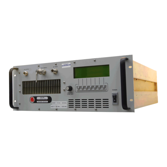
CONTENTS ( For a typical Wide Band Amplifier ) Quantity Description High Power Wide Band Amplifier, P/N SMX100 MS AC Connector Operation and Instruction Manual, Doc. No. SMX100MAN Amplifier Data Sheets (Included in this Manual) FIGURE 1.0... -
Page 5: General Description
SECTION 2.0 GENERAL DESCRIPTION The Instruments For Industry, Inc. ( IFI ) manufactured SMX100 Wide Band Amplifier is a Bench Top or rack mount amplifier providing 100 Watts of RF power from 10 kHz to 1000 MHz. The SMX100 incorporates two frequency bands of operation identified as Band 1 and Band 2 which provides the operator easy frequency band switching without changing the RF Output connections. -
Page 6: Ac Connection And Set-Up
2.1 AC Connection and Set-Up If your amplifier is equipped with a MS Connector for a power connection, the following instructions will assist a qualified technician to wire the supplied mating MS Connector. Determine whether your amplifier is Single Phase or Three Phase by locating the Serial Number Label and noting the Phase (PH) identification. -
Page 7: Warranty Information
This warranty is the full extent of obligation and liability assumed by IFI with respect to any and all IFI products. IFI neither makes, nor authorizes any person to make, any other guarantee or warranty concerning IFI Products. -
Page 8: General Information
4.1 SCOPE OF THIS MANUAL This manual is intended to inform a qualified transmitter operator or technician of the normal operating and maintenance procedures for the SMX100. It is not intended to be a course of instruction for unqualified personnel. -
Page 9: Protection Circuits
4.3.2 Input Protection The SMX100 is designed to operate with less than a 0 dBm ( 1.0 mW ) input signal however, to prevent overdriving the amplifier, the Input Protection circuit will activate if the input signal exceeds 3 dBm ( 2.0 mW ) and will automatically compensate for the increased input signal by reducing the... - Page 10 4.3.5 Mismatch Protection The SMX100 is designed to operate with a tuned 50 Ohm load and should any mismatching of the 50 Ohm load occur, the Reverse Power, also called Reflective Power, will increase producing a high VSWR.
-
Page 11: Status Indicators, Controls And Connectors
4.4 STATUS INDICATORS, CONTROLS AND CONNECTORS The SMX100 has various controls and status indicators, which are identified below and can be visually located on Figure 1.0, SMX100 Illustration and Figure 2.0, SMX100 Rear Panel Illustration. A narrative description for the function and purpose of each control and status indicator is provided within paragraphs 4.4.1 and 4.4.2. - Page 12 4.4.1 SMX100 PANEL STATUS INDICATORS INDICATOR FUNCTION FAULT INDICATOR The Fault indicator displays a fault when either a Thermal, Power Supply or Module Fault occurs on Front panel display. Some units may have Green Status LED Indicators in addition to the Controller Display.
- Page 13 4.4.2 SMX100 CONTROLS CONTROL FUNCTION Local When depressed, the amplifier is restored to the local control from the GPIB mode of control. ALC Switch (Option) The optional Automatic Leveling Control (ALC) is a feature, which selects the method for leveling, either internal, external or manual.
-
Page 14: Operating Instructions
4.5 OPERATING INSTRUCTIONS 4.5.1 Power On FIGURE 3.0 – FRONT PANEL DISPLAY (START-UP MENU) Apply power to the unit using the front panel ON/OFF switch. When the circuit breaker or AC Power On switch is energized, the above menu will be displayed after the Microprocessor (MPU) booting cycle has completed. - Page 15 4.5.3 - Entering the GPIB Address FIGURE 4.0 - GPIB ADDRESS MENU From the START-UP Menu in Figure 3.0, press the button located under the GPIB ADDR indication on the display. In this screen, Figure 4.0, the GPIB Address is entered by dialing in the desired number using the Control Level Adjust knob and pressing the RETURN button.
-
Page 16: Turning On The Amplifier
4.5.4 Turning ON the Amplifier FIGURE 5.0 – MAIN MENU AND STATUS DISPLAY (Typical) The amplifiers status can be monitored using the Main Menu. The Gain (GAIN), Total Hours (TOTL HRS), Operating Hours (OPRT HRS), Forward (FWD) and Reflected (RFL) statuses are continuously displayed. - Page 17 FIGURE 6.0 – TURNING ON THE AMPLIFIER (Typical) 1. From the MAIN MENU in Figure 6.0, press the button located under the Operate/Standby (OPR/STB) indication on the display. Place the unit in Operate (OPR) mode. At this mode the AMPLIFIER will be turned ON. 2.
-
Page 18: Data Sheets
4.6 DATA SHEETS Provided with each SMX100 are specific Amplifier Data Sheets measured from the amplifier using a calibrated 50 Ohm Pad to assist the operator in maximizing the performance of the Wide Band Amplifier. The Amplifier Data Sheets are provided with each amplifier exhibiting the actual metering indication required to produce rated power output as indicated on the data sheet. -
Page 19: Principals Of Operation
5.1.2 Input Signal Levels The SMX100 is designed to operate with less than a 0 dBm ( 1.0 mW ) input signal however, to prevent over driving the amplifier, the Input Protection circuit will activate if the input signal exceeds 3 dBm ( 2.0 mW ) and will automatically compensate for the increased input signal by reducing the... -
Page 20: Features Of The Amplifier
RF Relays to the Band 1 PA and Driver section which in then to the output. With the SMX100 in the High Band ( BAND 2 ) mode of operation, the input signal is directed by RF Relays to the Band 2 PA and Driver section which in then to the output. -
Page 21: Level Control Board
5.3.1 Automatic Level Control (Option) In this mode, the SMX100 serves as the voltage comparator and variable gain stage. It will enable the maintenance of a constant RF voltage vs. frequency at the input to an imperfect load or a virtually constant E-Field at a measurement point in space. -
Page 22: Automatic Leveling Control (Alc )
SECTION 6.0 AUTOMATIC LEVELING CONTROL (Optional) 6.1 ALC FEATURES The Automatic Leveling Control ( ALC ) switch located on the front panel has three positions, 'INT', 'OFF' and 'EXT'. Described below are the features of each position Important Note: Figures 5.0 and 6.0 indicates the display for a typical amplifier and the ALC option is indicated however if the amplifier is not equipped with this option, the ALC option will not be displayed. -
Page 23: Leveling Using The "Int' Mode
6.1.3 The 'EXT' or External Position The SMX100 serves as the voltage comparator and variable gain stage. It will enable the maintaining of a constant RF voltage vs. frequency at the input to an imperfect load or a virtually constant E-Field at a measurement point in space. -
Page 24: Leveling Using The 'Ext' Mode
Connect the ALC on the rear panel to the detected output port on the remote detector. Connect the remote detector in series with the SMX100 output and at the input to the load. The system is now ready for operation. Amplitude adjustments can be made with the level control as in manual operation. - Page 25 The Test Set-Up Procedure, refer to Figure 8.0 for a Typical ‘E’ Field Leveling set-up 1) Connect the RF Output of the Signal Generator to the RF Input of the SMX100. 2) Connect the RF Output of the SMX100, located on the same panel as the RF Input connector, to the antenna.
-
Page 26: E-Field Leveling Set-Up
6) The system is now ready to be tested with a swept analog or stepped frequency input signal. All IFI component blocks shown in Figure 8.0 are capable of operating continuously from 10 kHz to 220 MHz. Extended frequency coverage, over the full range of the unit, can be provided by substituting an EFS-5 for the EFS-1 and adding a second log periodic or ridged horn antenna. -
Page 27: Ieee-488 Interface Option
IEEE-488.2 Standard is implemented, which defines the protocols and syntax of commands. The GPIB command codes for the IFI Amplifier series are discussed on subsequent pages and, for ease of identification; the command codes are identified within the text by bold capital characters. -
Page 28: Gpib Address
7.3 GPIB ADDRESS The GPIB address of the amplifier is set by via the Front panel using the Control knob at the start up menu. NOTES ON USING NATIONAL INSTRUMENTS' GPIB CONTROLLERS: In order for the amplifier to operate correctly with a National Instruments GPIB controller card, the following must be done: (Items 1-5 are done in the IBCONF program.) 1. -
Page 29: Status Commands
7.4 STATUS COMMANDS IEEE COMMANDS FOR SOLID STATE AMPLIFIER CODE AMPLIFIER FUNCTION STBY Standby OPRT Operate RESET Fault Reset ATTU Increase Attenuation [Response with Gain value](optional) Decrease Attenuation [Response with Gain value](optional) ATTD REQUEST STATUS CODE AMPLIFIER STATUS STATUS STANDBY OPERATE FAULT FAULT... - Page 30 REQUEST AMPLIFIER STATUS (POWER AND METERING) CODE AMPLIFIER FUNCTION Returns Forward Power Value POWERFWD POWERRFL Returns Reflected Power Value Returns Power Supply 1 Volts Value PS1V PS1I Returns Power Supply 1 Current Value PS2V Returns Power Supply 2 Volts Value [when applicable] PS2I Returns Power Supply 2 Current Value [when applicable] TOTALH...
-
Page 31: Rs-232 Instructions
7.5 RS-232 INSTRUCTIONS (Option) RS-232 Operation of Serial Port on RF Amplifier 1.0 Connect serial port of amplifier to computer using a null modem cable or a standard serial cable with a null modem adapter. 2.0 Use a program such as Hyperterm to communicate with the amplifier. (To reach “Hyperterm” on windows ’98 go to Start Programs Accessories... -
Page 32: Maintenance And Servicing
MAINTENANCE AND SERVICING 8.1 PERIODIC MAINTENANCE The only periodic maintenance required on the SMX100 amplifier system is ensuring that the cooling vents are not obstructed in such a manner that the airflow is restricted. Periodic cleaning of the vents may be required depending on the degree of dust in the atmosphere. -
Page 33: Equipment Return Procedure
In many cases, a faulty accessory could give the illusion that the equipment itself has failed. For this reason it is important to return all the accessories with the equipment. It is also IFI's policy to verify performance of all associated accessories of Section 1.0 before returning the equipment to service. -
Page 34: Amplifier Data Sheets
APPENDIX A AMPLIFIER DATA SHEETS Page... - Page 35 APPENDIX B DRAWINGS SMX100 BILL OF MATERIALS (BOM) 900703C INTERCONNECT DIAGRAM 500466 POWER/VSWR METERING BD. 500499-1 SWITCH/LED BOARD ASSY 500523 SS HALLEFFECT BD ASSY, 1 CHN 500540 PS, ENABLE XSTR BD ASS`Y Page...
- Page 36 BILL OF MATERIALS ITEM PART PRODUCT NUMBER DESCRIPTION SMX100-TEMPLATE AMPLIFIER, SS, 10K-1000MHZ, 100W, 115/230VAC, 50/60HZ, 1PH, 19W-24D-7H COMPONENTS Upper Level Component Part Desg Part Number Part Number Description Req'd Level Code SMX100-TEMPLATE 0A-100295 ASSY DWG, SMX100, 7"Hx24"D CHASSIS, New Controller...
- Page 37 SMX100-TEMPLATE 700544-6 CABLE, RIBBON, A1P7-LED/SW BD SMX100-TEMPLATE 700545-6 CABLE, RIBBON, A1P3-LCD DISPL SMX100-TEMPLATE 700588 HYBRID, DIVIDER, ASSY, 200-1000MHZ, 200W SMX100-TEMPLATE 700589-42 RIBBON CABLE ASSY, RS 232, 42" LONG SMX100-TEMPLATE 800100-03 CABLE, RF ASSY, EZ FLEX .141, SMA/MALE - N/MALE SMX100-TEMPLATE 800101-03 CABLE, RF, .141, SMA/M-SMA/M...
- Page 38 SMX100-TEMPLATE DIO-1N4007 DIODE SMX100-TEMPLATE DIO-UF5408 DIODE, RECT, HV, 1KV, 3A, 75NS SMX100-TEMPLATE DIS-DMF5005 DISPLAY, MODULE, LCD, 240X64 DO SMX100-TEMPLATE FAN-03245 FAN, GUARD, 6" OR 08126 SMX100-TEMPLATE FAN-4 FAN, 4 INCH GUARD SMX100-TEMPLATE FAN-JD24B2 FAN, 6", 24VDC (12-28VDC), 250CFM, 0.8 Static Pressure, 3500RPM SMX100-TEMPLATE FER-T502525T FERRITE CORES, TOROID, CN20 MATERIAL, SIZE 0.5"...
- Page 39 LOW-BAND GAIN CONTROL +28V +28V +28V HTSK ASSY 500466 -46dBc, NOMINAL N, FEMALE FWD SAMPLE INSTRUMENTS FOR INDUSTRY RONKONKOMA, NY RF BLOCK DIAG, SMX100 Size CAGE Code DWG NO R e v 01105 900703-STD Scale Sheet Tuesday, August 21, 2007...
- Page 40 K1-NC K1-NO K1-NO +24V CON6 TB1-5 DUAL BAND 80A INSTRUMENTS FOR INDUSTRY RELAY BD ASSY CON2 RONKONKOMA, NY 500532-1 SMX100, INTERCONNECT DIAG, NEW CNTRL Size CAGE Code DWG NO R e v 01105 900703-STD Scale Sheet Tuesday, August 21, 2007...
- Page 41 EXHAUST FAN 6" 24VDC UF5408 PHASE LINE-A LOAD-A LINE UF5408 LINE POWER PS2, 100-240 VAC NEUT QUAD NEUTRAL NEUT-1 NEUT-2 +12V AUTO RANGE PS1-FLT INPUT1 5V, +/- +12V +12V +24V INPUT2 REMOTE MPU BD ASSY 12V,24V -12V RS232 INPUT3 -12V -12V 500536 RQ65D...
- Page 42 +28V NOTE: PRELI MINARY SETTING FOR VSWR ADJUSTMENT SET TP8 TO 10.8V & ADJUST R19 UNTIL HIGH VS WR STOP FLASHING ON DISPLAY NINV IN SET TO 11.8V VOUT FOR NORMAL OPR. CUR LIM 1.2K CUR SEN VREF +12V INV IN 2.2K LM723 REV_PWR...
- Page 43 INSTRUMENTS FOR INDUSTRY, INC.
- Page 44 +12V 4.7K 10uF,35V 10K, 1/4W LM124 10K, 1/4W +12V 10K, 1/4W 1N751 10K, 1/4W P/N LA55P +12V PS1, +28V -12V -12V +12V -12V 10K, 1/4W HALL-EFFECT SENSOR OUTPUT LM124 POT,5K 1N751 10uF,25V 10K, 1/4W 0.01uF 22, 1/4W 20K,POT 1N751 PS1, +28V PS1, +28V, MONITOR PS1, +28V,FLT PS1 I NOM...
- Page 45 Date: 1/31/2007 Time : 09:43:29 AM 680,1/2W CON5 2N2222 1K,1/4W ASSY 500540 Title PS, ENABLE CKT Size Document Number 500540 Date: Friday, December 01, 2006 Sheet Title: T:\Engineering\Design-Final\500000, Orcad Schms\500540B, PS ENABLE CKT.DSN...
Need help?
Do you have a question about the SMX100 and is the answer not in the manual?
Questions and answers
Why does the manual contradict itself?!?!?!? "the correct command is "ZA\r\n" then the next page says the command is ZEROATT which like: ridiculous