Table of Contents
Advertisement
Quick Links
Advertisement
Table of Contents

Related Manuals for ASTRO EdgeQAM U 158


Summary of Contents for ASTRO EdgeQAM U 158
- Page 1 Operating manual U 158 8-way IP / QAM converter U 100 - 230 Base unit...
- Page 2 U158. We expressly recommend reading this manual before installing or operating the device. The ASTRO company confirms the information in this manual to be correct at the time of printing, but it reserves the right to make changes, without prior notice, to the specifications, the operation of the device and the operating manual.
-
Page 3: Table Of Contents
Table of contents Figures ........................4 1.1 Monitoring via rotary knob ................... 4 Introduction ......................5 2.1 Description of functions ..................5 2.2 Safety instructions ..................... 5 2.3 Mounting instructions ..................5 2.4 Potential equalisation / grounding ............... 6 2.5 Maintenance and repair ..................6 2.6 Service tasks .................... -
Page 4: Figures
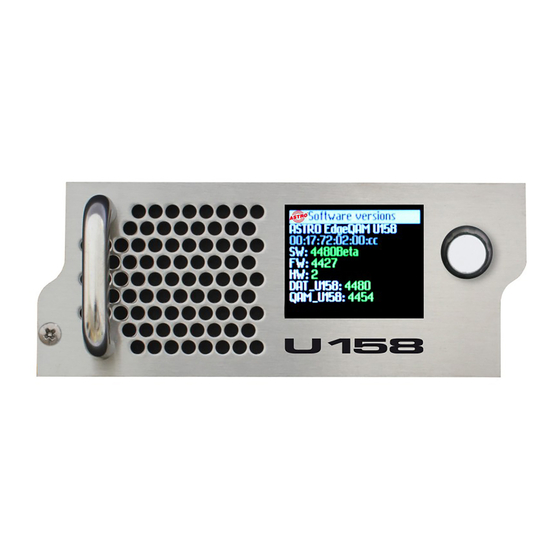
1 Figure The figures show the U 158 installed in the U 100 - 230 base device. Status display Status display for slots L = left Control and data wheel, menu switch M = middle R = right Display of management IP addresses, P = power supply data IP addresses, status messages, etc. -
Page 5: Introduction
The device may only be repaired by sending it to ASTRO along with a precise description of the error. Displays indicate the status of the device operation, as well as the existence of DC voltages separate from the mains that are supplying the components of the device. -
Page 6: Potential Equalisation / Grounding
U 100. Replacing power units After the screws on the cover of the power unit chamber (ASTRO logo) are removed,the power units can be pulled out by hand, forwards along the mounting panel. When power units are being installed, there should be no contact with the ventilator or the fan grid, and only the mounting panel attached to the power unit should be used. -
Page 7: Installing And Coding The Backplane
Installing and coding the backplane The scope of delivery of every U 1xx signal converter includes a backplane to create the physical connection between the signal converter and the base device. Both the mains HF connections and the network connections are connected to this backplane. The temperature controlled fan for cooling the U 1xx signal converter is located on the backplane. -
Page 8: Installing The Backplane
2.8.2 Installing the backplane In its state on delivery, the back of the U 100 base device is covered with blind panels: Phillips screws Figure 2: Position of the blind panel on delivery of U 100 To remove the blind panel, unscrew the two Phillips screws indicated in the above figure and remove the blind panel. -
Page 9: General Introduction
3 General introduction 3.1 Connecting the U 158 to a PC / laptop When the operating voltage is connected, or after it is inserted into the slot of the base device, the U 154 switches on automatically. After the boot phase (ca. 90 seconds), will be displayed status messages. -
Page 10: Login
In the state on delivery, the login data is as follows: User: admin or user Password: astro After correctly entering the login data, you can proceed with the configuration. Note: For security reasons, the user names and passwords should be changed from the state on deli- very. -
Page 11: Status
Status When you click on the “Status” submenu in the left frame, the following window appears (example) Ethernet status Status display of the IP receivers Status display of the HF output channels Here all the relevant Display of diverse data for the status of status messages on the U 158 is displayed the module tempera-... -
Page 12: Settings For The Ip Interfaces, Ip Management And Base Device
Settings for the IP interfaces, IP management and base device When you click on the “Main” submenu in the left frame, the following window appears (example): Figure 5: Overall view The settings available are described in detail in the following sections. Operating Manual U 158 8-way IP / QAM Converter... -
Page 13: Configuration Of The Ip Interfaces
6.1 Configuration of the IP interfaces In the area of the user interface displayed below you can activate and deactivate the IP interfaces. The connection type is automatically detected and displayed by the U 158 . (Here: 1 GBit/s, full duplex for Data A&B and 1 GBit/s, full duplex for Management A&B). Figure 6: IP interface configuration Changes in the IP addresses can only be done by the admin (account 1 in the user administration, see chapter 10). -
Page 14: U 100 Settings
6.3 U 100 settings Under “U 100 Rack Settings” an address can be allocated to the relevant base device. This setting affects all other signal converters in the base unit. The number of the currently selected slot is displayed below it: Figure 8: Rack Settings 6.4 Saving and loading a configuration, default and reboot The current configuration of the U 158 is always written to the device using the “Submit”... -
Page 15: Test Generator
Test generator The U 158 has an integrated test generator for checking the functions of the QAM modulators when no input signal is available yet. The max. data rate that can be set is 67 MBit/s. Figure 10: Test generator settings If you choose the testgenerator at “... -
Page 16: Configuration Of The Ip Inputs
Configuration of the IP inputs When you click on the “IP RX” submenu in the left frame, the following window appears (example): Figure 11: Overview of the IP input configuration Here the four IP inputs to be configured are activated or deactivated, and their current configura- tion is displayed. - Page 17 Figure 13: Setting the Multicast addresses The “use” selection box defines the data source used. This data source is defined via the Multicast address and can - if this Multicast address is provided by multiple senders - be used preferentially by the IP receiver.
-
Page 18: Configuration Of The Hf Outputs
IP RX 1 to IP RX 8 are displayed. The last possible option to choose from is the ASTRO test generator, which creates a digital radio program with a 1 kHz tone in the adjusted output channel. -
Page 19: Adjusting The Output Channel
In the column „Symbol Rate“, the configured symbol rate of the output channels are displayed. Further information concerning the output channel are shown in the column „Standard Bandwidth Constellation TS Rate“. This information is: QAM Standard, the bandwidth of the output channel, the type of modulation and the output data rate. -
Page 20: Operation With Output Channel Filter
9.1.3 Operation with output channel filter If an output channel filter (U-KF…) is plugged to the U 158, this channel filter will be recognised by the device. This leads to the activating of the option „Channel filter On / Off“. If no filter is assembled, this option remains inactive. -
Page 21: Detail Adjustments Of The Qam Output Channels
9.2 Detail adjustments of the QAM output channels By clicking to the submenus RF 1.1, RF 1.2, RF 1.3, RF 1.4, RF 2.1, RF 2.2, RF 2.3 or RF 2.4, the following window opens up as an example: Figure 20: Detail settings of the output channel In this subpage all details of the output channel can be set. -
Page 22: Processing The Transport Stream
The U 158 is able to generate QAM channels according DVB-C standard annex A/ C or accor- ding ITU-T J.83 annex B. This choice is done in the line “Standard”. Depending on the chosen standard, the options in line “Defaults” change. In this line, the choice for the type of modulation and for the channel bandwidth is made. -
Page 23: Nit-Processing
The U 158 offers a PID-remap function. This means that PIDs at the input can be renamed and fed into the output data stream with a new PID name. For setting such filter, a PID from the drop down menu has to be chosen. The new name of this PID must be typed into the field „Output- PID“... -
Page 24: Generating A Static Nit
9.3.4 Generating a static NIT The static NIT can be generated like in the sample below: Insertion of the network ID and network name Insertion of the TS details: TS-ID, ON-ID, output frequency, constellation and symbol rate Adding of TS via „Add“ button. Display of the NIT with all entries: NIT can be sorted... -
Page 25: User Management
You reach the user management by clicking on the “User” submenu. The U 158 allows you to create four different users. In the state on delivery, “admin”, “user” and “bc4” are created, all with the password “astro”. Only an admin account is able to change IP settings and the option “Lock RF relevant settings”. -
Page 26: Transport Stream (Ts) Analyzer
11 Transport Stream (TS) Analyzer The U 154 can be equipped with a Transport Stream Analyzer by obtaining a licence. This Analy- zer displays the structure of the MPEG2 TS, from the tables to the individual PID and its service. You click on the “TS Analyzer”... -
Page 27: Licensing
Some functions of the U 158 (e.g. the TS Analyzer) must be activated using a licence key. The licence key can be obtained from ASTRO along with the function. The text sent is then copied into the text input field and transferred to the device using “Submit”. -
Page 28: Software Update / Saving And Loading A Configuration
13 Software update / saving & loading a configuration By clicking on the “Update” submenu in the left frame, the following window appears: Figure 25: Action selection in the “Software Upgrade” submenu Here you have the option to initiate different actions via (T)FTP. To configure the U 158 for these actions, the server address (line “(T)FTP server address”), the used protocol (line “Protocol”), the username and password (line “FTP username (e.g. -
Page 29: Update Using Example Of A Tftp Server For Windows
If the U 158 is working from the backup area, you must not start the action “Overwrite backup firmware”. This leads to a total malfunction of the device which can only be recovered by sending the device to ASTRO! 13.1 Update using example of a TFTP server for Windows If no fixed (T)FTP server is set up for the update, you also have the option to transfer locally saved update files onto the device. - Page 30 NOTE: A reboot or a network failure during an update process can cause the U 158 software to crash irrevocably. The device then has to be returned to ASTRO for repair. Operating Manual U 154 quad IP / QAM converter...
-
Page 31: System Log
14 System Log Clicking on the “System Log” submenu takes you to the log of the U 158 . All the procedures rele- vant to the operation of the device are documented here. Additionally, the SNMP settings are made here (defining the trap recipients, the trap community & the trap filter). Also, the “Log file filter” line can be used to define which events lead to an entry in the log. -
Page 32: Statistics
15 Statistics Clicking on the “Statistics” submenu takes you to the statistics for the data transfer of the U 158 . Here all the statistics relevant to the operation of the device and its analysis are displayed. Figure 29: Statistics for the data transfer Operating Manual U 158 8-way IP / QAM Converter... -
Page 33: Network Properties
16 Network properties You reach the network properties by clicking the “Network Monitor” submenu. The proper- ties displayed are purely for information pur- poses, and are used to describe the network. Figure 30: Example view of the network properties in the “Network Monitor” submenu Operating Manual U 158 8-way IP / QAM Converter... -
Page 34: Logout
17 Logout Clicking on the “Logout” submenu (only available when you are logged in) takes you to the logout of the U 158 . Figure 31: Logging out of the U 158 If you confirm the request by clicking “Yes”, you are logged out. No further settings can be made without logging in again, but you do have the option to view the settings of the U 158 . -
Page 35: Technical Data
18 Technical data Type U 100 - 48 U 100 - 230 Order number 380 100 380 101 EAN-Code 4026187611064 4026187611149 Network interfaces (passive routing to U 1xx) Management 2 x 100 Base-T Ethernet (RJ 45) Data 2 x 1000 Base-T Ethernet (RJ 45) Protocol IEEE802.3 Ethernet, RTP, ARP, IPv4, TCP/UDP, HTTP, SNTP, IGMPv3 Transport stream editing... - Page 36 ASTRO Strobel Kommunikationssysteme GmbH Olefant 1–3, D-51427 Bergisch Gladbach (Bensberg) Tel.: 0 22 04 / 4 05-0, Fax: 0 22 04 / 4 05-10 eMail: kontakt@astro-kom.de, www.astro-kom.de...
Need help?
Do you have a question about the EdgeQAM U 158 and is the answer not in the manual?
Questions and answers