Subscribe to Our Youtube Channel
Summary of Contents for GAPOSA QC400
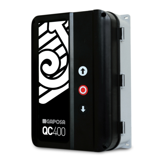
- Page 1 QC400 PANTONE 302C Automatic control unit for three/single-phase motors RAL 5000 with digital or mechanical limits C 100 M 30 K 50 PCB VERSION 7-0217 R1717 VERSION – SOFTWARE V05_00...
-
Page 3: Important Safety Instructions
DESCRIPTION The QC400 has been designed to operate an industrial door safely under electrical control of a pushbutton or key switch. Its intended use is to be connected to a suitable motor not exceeding the load for the controller. Connections are provided for mains supply (both 3ph and 1ph), motor power, mechanical or electronic limits, Push Buttons, Pneumatic or Electrical or Optical Safety Edge, Photo beam safety and 24VDC Auxiliary power (100mA max). -
Page 4: Technical Details
TECHNICAL DETAILS Installation Vertical on a vibration free and flat wall Temperature range (operating) -10…+50°C Humidity Up to 93% RH non-condensing. Vibration Low-vibration installation, wall mounted. Supply voltage: 3ph - 230/400V~ ± 10% L1,L2,L3,PE (‘N’ required ONLY for services - see par. 7/9) (Selectable by jumper 1~ 230V~ ±... - Page 5 QCF4 PHOTOCELL ENCODER FOR ELECTRONIC LIMITS MECHANICAL LIMIT SWITCHES CLOSE LIMIT OPEN LIMIT ATTENTION! In case of MECHANICAL ENCODER LIMIT SWITCHES COM OL CL SAFETY PHOTO 24 V OUTPUT terminals 2 and 5 of the OPEN BUTTON connector X6 must be jumped 12 11 10 9 8 7 6 5 4 3 2 1 STOP BUTTON...
-
Page 6: Installation
1 INSTALLATION For a correct installation: • Install where the control unit can be protected from rain or adverse weather conditions • Mounting must be vertical • The mounting surface must be flat and not be subject to vibrations • Do not install in an area of potential risk of condensation • It is important that the door can be clearly seen from the position of the control while operating • Install in an area not accessible to children or unauthorized persons • Do not perform any electrical connections before the installation is completely accomplished... -
Page 7: Dip Switch Functions
3 DIPSWITCH FUNCTIONS 1 2 3 4 5 6 7 8 9 10 NOTE OPERATING LOGIC Dead-man OPEN/CLOSE Impulse OPEN/CLOSE Impulse OPEN / Deadman CLOSE OPTIONS Auto close (after delay time) Electronic after run / edge monitoring Force control (Multiturn) (NOT AVAILABLE AT THE MOMENT) Force control fine sense (NOT AVAILABLE AT THE MOMENT) - Page 8 In particular, the motor will not find the limit positions and this could put at risk the safety of peo- ple and/or things. In order to connect the QC400 with a motor with mechanical limits set the DIP10 on S3 in OFF (See 4.1 PROGRAMMING). 1 GREY >...
- Page 9 4.1 PROGRAMMING WITH MECHANICAL LIMIT SWITCH ATTENTION: to let the safeties work, these must be connected before starting the control unit setup. Setup process - Mechanical limits standard Set DIP10 in OFF position for selecting mechanical limits and DIP1 and DIP2 to OFF position for deadman operation. Standard control for mechanical limits are for PNE edge type (3-4 terminals on X5) and no photo connected.
- Page 10 In particular, the motor will not find the limit positions and this could put at risk the safety of peo- ple and/or things. In order to connect the QC400 with a motor with electronic limit switch: 1. Remove the 3pins white terminal from the cable (our part # FLCE31W012 ) - Fig. 1 2.
- Page 11 5.1 PROGRAMMING WITH ELECTRONIC LIMIT SWITCH ATTENTION: to let the safeties work, these must be connected before starting the control unit setup. Setting process Turn OFF the power and connect the encoder and all safety equipment. The controller memorises the encoder type by power-up. Set DIP10 in ON position and turn the power ON.
- Page 12 6 BRAKE RELAY CONNECTIONS ON AUX 1 Brake can be used for both mechanical and electronic limits. AUX1 output is going OFF 30 ms before motor contactor is turned ON for releasing the brake a brief time before motor starts. External Relay AUX1 output is going ON 20 ms Brake...
- Page 13 9 PLUG-IN TRAFFIC LIGHT QCLSM (OPTIONAL) This is a plug-in board to be used with the QC400 in order to control flashing lights, courtesy lamps or traffic lights during the operation of the door or shutter.
- Page 14 10 SPECIAL TECHNICAL INFORMATION Go Func normal : Go function input terminal X5-11,12. (DIP7 OFF) Go function, when photo safety is connected to controller: When Door is not open > the door will open. When door is open > the door will start closing. When door is running down >...
- Page 16 Gaposa srl - via Ete, 90 - 63900 Fermo - Italy T. +39.0734.220701 - F. +39.0734.226389 - info@gaposa.com www.gaposa.com 0119...


Need help?
Do you have a question about the QC400 and is the answer not in the manual?
Questions and answers