Table of Contents
Advertisement
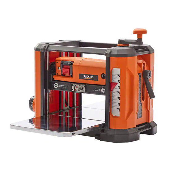
OPERATOR'S MANUAL
13 inch Portable Planer
R4850
Your saw has been engineered and manufactured to our high standard for dependability, ease of operation, and operator
safety. When properly cared for, it will give you years of rugged, trouble-free performance.
WARNING:
To reduce the risk of injury, the user must read and understand the operator's manual before using this product.
SAVE THIS MANUAL FOR FUTURE REFERENCE
Advertisement
Table of Contents

Related Manuals for RIDGID R4850


Summary of Contents for RIDGID R4850
- Page 1 OPERATOR’S MANUAL 13 inch Portable Planer R4850 Your saw has been engineered and manufactured to our high standard for dependability, ease of operation, and operator safety. When properly cared for, it will give you years of rugged, trouble-free performance. WARNING: To reduce the risk of injury, the user must read and understand the operator’s manual before using this product.
-
Page 2: Table Of Contents
UNPACKING ............8 FUNCTIONAL DESCRIPTION FOREWORD The RIDGID Model R4850 is a 13 inch (330mm) Portable Planer ® Specifications: that has a cutting capacity of 13 inch (330mm) wide, 6 inch (152mm) thick and 1/8 inch (3.2mm) deep. This machine has a Model: R4850 powerful 15 amp 120 volt motor with a three-knife cutterhead. -
Page 3: Features
FEATURES Cutterhead Height Adjusting Handle Micro Adjustment Main Housing Indicator Arrow Base In-feed Table Depth Stop Knob / Lock Material Removal Gauge On/Off Switch Reset Button Dust Deflector Wear Table Out-feed Table Cutterhead Lock Handle Wrench Storage (Under Table) Dust Collection Attachment FIGURE 1... -
Page 4: Safety Guidelines - Definitions
OTHER THAN THAT FOR WHICH IT WAS DESIGNED. If you have any questions or concerns relative to the use of your tool or the contents of this manual, stop using the tool and contact 1-888-359-4778 RIDGID Customer Service (toll free) ®... -
Page 5: General Safety Rules
GENERAL SAFETY RULES Failure to follow these rules may result in serious personal injury. For your own safety, read the instruction manual and attachments not recommended by RIDGID ® before operating the machine. Learning the machine’s cause damage to the machine or injury to the user. -
Page 6: Additional Specific Safety Rules
ADDITIONAL SPECIFIC SAFETY RULES FAILURE TO FOLLOW THESE RULES MAY RESULT IN SERIOUS PERSONAL INJURY. DO NOT OPERATE THIS MACHINE until it is completely to prevent kickback. assembled and installed according to the instructions. A 16. DO NOT FEED A WORKPIECE that is warped, contains knots, machine incorrectly assembled can cause serious injury. - Page 7 ADDITIONAL SPECIFIC SAFETY RULES POWER SOURCE This saw is equipped with a 15-amp motor for use with a 120-volt, 60-HZ alternating current. For voltage, the wiring in a shop is as important as the motor’s rating. A line intended only for lights may not be able to properly carry the current needed for a power tool motor;...
-
Page 8: Unpacking
UNPACKING UNPACKING AND CLEANING This machine weighs about 75 pounds. Use a helper to lift or move it. Carefully unpack the machine and all loose items from the shipping container. Figure 2 illustrates the planer and all loose items supplied with your machine. -
Page 9: Assembly
ASSEMBLY To reduce the risk of injury, turn unit off and disconnect the machine from power source before installing and removing accessories, before adjusting or when making repairs. An accidental start-up can cause injury. ASSEMBLY TOOLS REQUIRED T-handle Torx wrench (Supplied) HOW TO ATTACH THE CUTTERHEAD LOCK HANDLE... - Page 10 ASSEMBLY HOW TO PREPARE FOR DUST MANAGEMENT You have two options for dust management. The first is the dust deflector and the second is the dust collection attachment to at- tach your machine to a dust collector. Note: The dust deflector comes factory installed and can be used if the user elects not to use a dust collector system.
-
Page 11: Operation
ASSEMBLY HOW TO FASTEN THE PLANER TO A SUPPORTING SURFACE Before operation, secure the planer to the supporting surface. Four holes (two of which are shown at Figure 9) are provided for this purpose. Operate the planer on a flat, level surface. Four attachment holes are provided for mounting the planer to a stand or work surface. - Page 12 OPERATION How to Use the Cutterhead Lock The cutterhead lock Figure 13 helps to eliminate snipe in the board that is being planed. Snipe can also be eliminated by butting boards end to end and feeding them through the planer. Long boards should ALWAYS be supported, when feeding them through the planer to help eliminate snipe.
- Page 13 OPERATION NOTE: DO NOT exceed the recommended depth of cut for various widths of material, shown in the “RECOMMENDED 1/8 inch DEPTH OF CUT” section below. (3.2mm) DO NOT turn the unit “ON” with the workpiece 3/32 inch in position. (2.4mm) SOFT WOOD 1/16 inch...
- Page 14 OPERATION How to Use the Adjustable Indexing Ring The cutterhead height adjusting handle has an adjustment ring Figure 18. The Adjustable Index Ring is best utilized after the initial cut has been made. To use the adjustment ring to make fine adjustments: Once the initial cut has been made and fine tuning is required, measure the thickness of a planed board.
-
Page 15: Maintenance/Adjustment
OPERATION Snipe Snipe is a depression made when an unsupported end of your material drops toward the floor, causing the opposite end to lift up into the cutter head. To Avoid Snipe Feed the workpiece into the planer so it is level and remains flat against the table at all times. Keep the workpiece level throughout planing operation by receiving or “catching”... - Page 16 MAINTENANCE/ADJUSTMENT Place the magnetized end of the wrench at the center of the knife. Lift the wrench until the knife separates from the pins. Remove the knife. Repeat steps 3 through 5 to remove the other two knives. Press down the cutterhead lock release and use the supplied wrench to rotate the cutterhead until the lock engages and the next knife is in position to be...
- Page 17 MAINTENANCE/ADJUSTMENT How to Adjust the In-Feed and Out-Feed Tables Your unit has been factory set to eliminate snipe. If your unit loses its adjustment and causes snipe, you can adjust the in-feed and out- feed tables to minimize this condition. Raise the cutter head.
- Page 18 RIDGID brushes. ® Replacing the Drive Belt FIGURE 28 Drive belts are available at extra cost at RIDGID authorized service centers. Replacement of the drive belt should be performed by ® qualified service personnel. Keep Machine Clean Periodically blow out all air passages with dry compressed air. All plastic parts should be cleaned with a soft damp cloth.
-
Page 19: Troubleshooting
® ® ® Service Centers. Please visit our Web Site www.RIDGID.com for an online catalog or for the name or your nearest supplier. Since accessories other than those offered by RIDGID have not been tested with this product, use of ®... -
Page 20: Parts, Service Or Warranty Assistance
® cover any malfunction, failure or defect resulting from (toll free) 1-888-359-4778. misuse, abuse, neglect, alteration, modification or repair by other than an authorized service center for RIDGID 90-DAY SATISFACTION GUARANTEE POLICY ® branded stationary power tools. Consumable accessories During the first 90 days after the date of purchase, if you... - Page 21 13 inch Portable Planer R4850 Customer Service Information: For parts or service, do not return this product to the store. Contact your nearest RIDGID ® authorized service center. Be sure to provide all relevant information when you call or visit. For the location of the authorized service center nearest you, please call 1-888-359-4778 or email us at RidgidWoodworking@ridgidproducts.com.
Need help?
Do you have a question about the R4850 and is the answer not in the manual?
Questions and answers