Advertisement
Quick Links
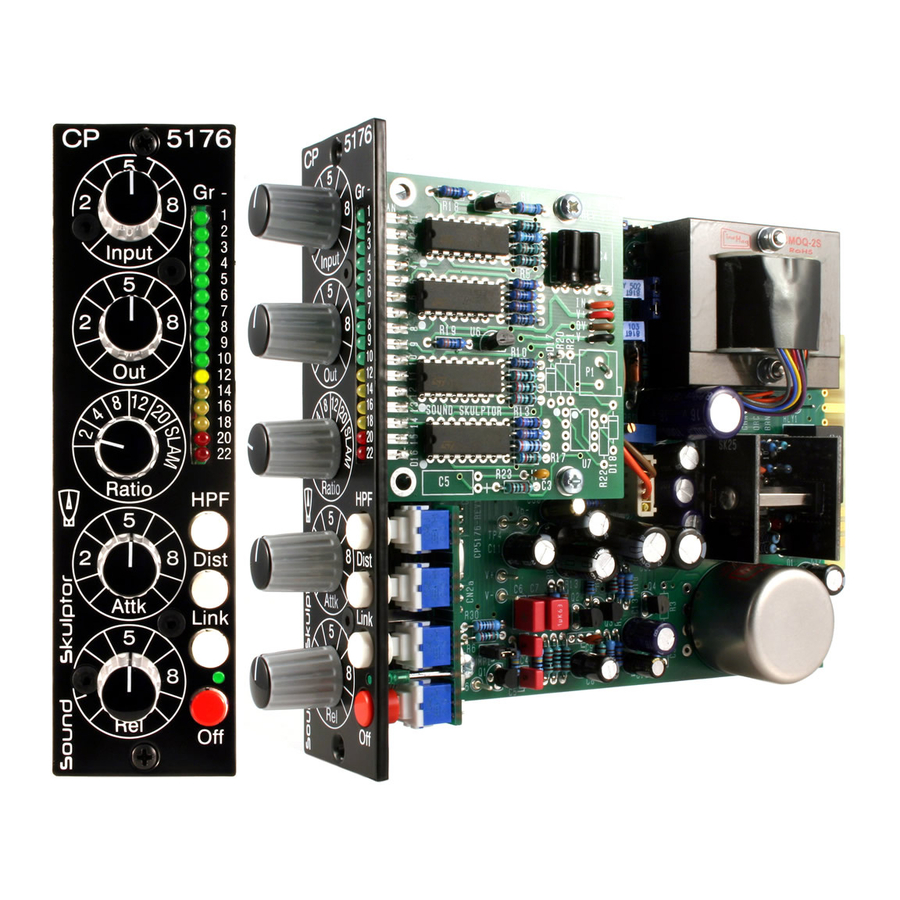
CP5176 Assembly guide
Safety warning
The kits are main powered and use potentially lethal voltages. Under no circumstance should someone undertake the
realisation of a kit unless he has full knowledge about safely handling main powered devices.
Please read the "DIY guide" before beginning.
Print or open the following documents :
• CP5176 Schematics
• CP5176 Components layout
• CP5176 Parts list
• CP5176 Setup guide
Follow this guide from item number 1 till the end, in this order. The assembly order is based on components height, from
low to high profile, in order to ease the soldering process : The component you are soldering is always taller than the
previously assembled ones and it is pressing nicely against the work area foam.
CP5176 Assembly guide – Main PCB
1.
PCB to PCB connectors
Insert the male, 90° angled, 2x10 connectors into the corresponding 2x10 sockets and put them in
place, flat under the PCB. Solder.
: The connectors are installed on the solder side of the PCB.
Warning
Warning
: It is important not to split the PCB before this step as the small PCB is used to line up the
connectors horizontally.
Copyright ©2013 to Today SoundSkulptor
Document revision 1.3 – Last modification : 26/03/17
www.soundskulptor.com
Advertisement

Related Manuals for Sound Skulptor CP5176


Summary of Contents for Sound Skulptor CP5176
- Page 1 : The component you are soldering is always taller than the previously assembled ones and it is pressing nicely against the work area foam. CP5176 Assembly guide – Main PCB PCB to PCB connectors Insert the male, 90°...
- Page 2 Document revision 1.3 – Last modification : 26/03/17 CP5176 Assembly guide – Main PCB PCB split Split the PCB along the groove, taking care not to press on the connectors. DOA Pin Sockets Solder the 7 pin sockets for the DOA. Solder one at a time.
- Page 3 Document revision 1.3 – Last modification : 26/03/17 CP5176 Assembly guide – Main PCB IC Sockets Insert and solder the 14 pins sockets of UI and U2. Warning : Make sure to respect the socket direction, marked by a notch.
-
Page 4: Electrolytic Capacitors
Document revision 1.3 – Last modification : 26/03/17 CP5176 Assembly guide – Main PCB 10. Ceramic capacitors Add C9, C16, C26. Warning : Some capacitors have provision for 2 sizes. Small size capacitors must be inserted in the correct holes as shown in the picture. -
Page 5: Output Transformer
Document revision 1.3 – Last modification : 26/03/17 CP5176 Assembly guide – Main PCB 18. Output transformer 1 Washer The transformer is mounted using two 25mm M3 screws inserted from the back of the board. Two metal washers are fitted on each screw to prevent the transformer touching the PCB. - Page 6 Make a full visual check. Any missing component on the board ? Any remaining component in the box ? When everything looks correct, proceed with the front PCB assembly. CP5176 Assembly guide – front PCB assembly Resistors Add R14, R34... R38, R42... R45.
- Page 7 Document revision 1.3 – Last modification : 26/03/17 CP5176 Assembly guide – front PCB assembly Diode Add D3. Warning : Make sure to respect the direction of the diode which is marked by a ring on the component and letter K on the PCB marking.
- Page 8 Document revision 1.3 – Last modification : 26/03/17 CP5176 Assembly guide – front PCB assembly Push buttons Insert the caps on the push buttons. Insert the push buttons, flat, in the correct direction and solder only one pin. Warning...
-
Page 9: Integrated Circuits
Document revision 1.3 – Last modification : 26/03/17 CP5176 Assembly guide – Gain reduction meter LEDs For each one of the 16 LED's cut the short leg (cathode) at 5mm from body and cut the long leg (anode) at 6mm. - Page 10 Document revision 1.3 – Last modification : 26/03/17 CP5176 Assembly guide – Gain reduction meter Electrolytic capacitors Add C1, C2. Warning : The +lead must go into the +hole. Do not reverse (they may explode !) Regulator IC's Add U5 and U6. Press the IC's down as far as possible in order to keep the components height low.
- Page 11 Attach the GR meter on the two spacers with two M3x6 screws, making a loop with the cable under the PCB. Don't plug the cable yet. 13. Test and setup It is time for test and setup. Follow instructions on cp5176-setup-guide.pdf. Copyright ©2013 to Today SoundSkulptor...
- Page 12 Document revision 1.3 – Last modification : 26/03/17 CP5176 Assembly guide – Final assembly 14. Congratulations ! You're done ! Copyright ©2013 to Today SoundSkulptor...
Need help?
Do you have a question about the CP5176 and is the answer not in the manual?
Questions and answers