Advertisement
Quick Links
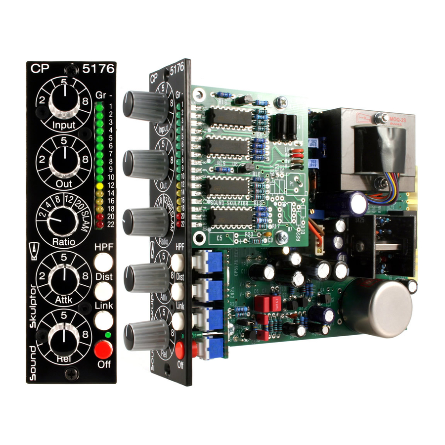
CP5176 Assembly guide
Safety warning
The kits are main powered and use potentially lethal voltages. Under no circumstance should someone undertake the
realisation of a kit unless he has full knowledge about safely handling main powered devices.
Please read the "DIY guide" before beginning.
Print or open the following documents :
• CP5176 Schematics
• CP5176 Components layout
• CP5176 Parts list
• CP5176 Setup guide
Follow this guide from item number 1 till the end, in this order. The assembly order is based on components height, from
low to high profile, in order to ease the soldering process : The component you are soldering is always taller than the
previously assembled ones and it is pressing nicely against the work area foam.
Soldering
All the PCB holes are metallized. It means the connection between the top and bottom pads is already
done. The parts must be soldered only from below (unless differently stated).
Use only small diameter solder, 0.5 or 0.7 mm, 1mm maximum. Use the minimum possible amount of
solder. Bad joints are almost always caused by too much solder.
Cut the component leads and pins totally flush with the PCB after soldering. A too long tail could create
an electric connection with the side plate.
Here are two excellent introduction to soldering videos:
http://www.eevblog.com/2011/06/19/eevblog-180-soldering-tutorial-part-1-tools/
http://www.eevblog.com/2011/07/02/eevblog-183-soldering-tutorial-part-2/
CP5176 Assembly guide – Main PCB
1.
PCB split
Split the second PCB along the groove. Use extra
thin sandpaper to clean up all the rough sides.
Copyright ©2013 to Today SoundSkulptor
Document revision 2.1 – Last modification : 12/11/17
www.soundskulptor.com
Advertisement

Related Manuals for Sound Skulptor CP5176


Summary of Contents for Sound Skulptor CP5176
- Page 1 Here are two excellent introduction to soldering videos: http://www.eevblog.com/2011/06/19/eevblog-180-soldering-tutorial-part-1-tools/ http://www.eevblog.com/2011/07/02/eevblog-183-soldering-tutorial-part-2/ CP5176 Assembly guide – Main PCB PCB split Split the second PCB along the groove. Use extra thin sandpaper to clean up all the rough sides.
- Page 2 Document revision 2.1 – Last modification : 12/11/17 CP5176 Assembly guide – Main PCB PCB to PCB connectors Insert the female 2x10 connectors on the male parts and position them on the solder side of the main PCB. Use the second PCB to create a flat continuous surface.
- Page 3 Document revision 2.1 – Last modification : 12/11/17 CP5176 Assembly guide – Main PCB Ceramic capacitors Add C10, C26, C17, C20, C21, C22. IC Sockets Insert and solder the 14 pins sockets of UI and U2. Warning : Make sure to respect the socket direction, marked by a notch.
- Page 4 Document revision 2.1 – Last modification : 12/11/17 CP5176 Assembly guide – Main PCB 11. Jumper headers Insert the 5 pins jumper header JMP1. Solder one pin first, check verticality, then solder the other pins. 12. Transistors and regulators Add Q1 to Q4 and U3.
-
Page 5: Output Transformer
Document revision 2.1 – Last modification : 12/11/17 CP5176 Assembly guide – Main PCB 19. Input transformer Pin 1 on the transformer is identified by a red dot. Insert the transformer, pin 1 into hole number 1 and solder. - Page 6 Document revision 2.1 – Last modification : 12/11/17 CP5176 Assembly guide – Main PCB 22. IC's Insert U1 and U2 into their sockets. It is necessary to bend the pins slightly inward before inserting. Warning: Make sure to insert the IC's in the correct direction which is identified by a notch.
- Page 7 Make a full visual check. Any missing component on the board ? Any remaining component in the box ? When everything looks correct, proceed with the front PCB assembly. CP5176 Assembly guide – front PCB assembly 26. Diode Add D3. This diode is installed vertically.
- Page 8 Document revision 2.1 – Last modification : 12/11/17 CP5176 Assembly guide – front PCB assembly 2mm LED Insert the 2mm LED, taking care of the anode/cathode position. The shortest leg (cathode) is the closest to the PCB edge. Temporarily attach the front panel with two M3x8 mm screws.
-
Page 9: Integrated Circuits
Document revision 2.1 – Last modification : 12/11/17 CP5176 Assembly guide – Gain reduction meter LEDs For each one of the 16 LED's cut the short leg (cathode) at 5mm from body and cut the long leg (anode) at 6mm. -
Page 10: Electrolytic Capacitors
Document revision 2.1 – Last modification : 12/11/17 CP5176 Assembly guide – Gain reduction meter Electrolytic capacitors Add C1, C2. These capacitors are installed below, on the solder side of the PCB. Warning : C1 & C2 are soldered under the PCB, on the solder side. - Page 11 11. Knobs Attach the 5 knobs to the 5 potentiometers and switch spindles. 12. Test and setup It is time for test and setup. Follow instructions on cp5176-setup-guide.pdf. Copyright ©2013 to Today SoundSkulptor...
- Page 12 Document revision 2.1 – Last modification : 12/11/17 CP5176 Assembly guide – Final assembly 13. Gain reduction meter assembly Attach the GR meter on the lower spacer with one M3x6 screw. Place the 4mm spacer on the higher hole 14.
Need help?
Do you have a question about the CP5176 and is the answer not in the manual?
Questions and answers