Advertisement
Quick Links
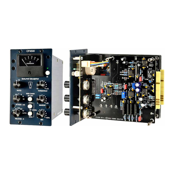
CP4500 Assembly guide
Safety warning
The kits are main powered and use potentially lethal voltages. Under no circumstance should someone undertake the
realisation of a kit unless he has full knowledge about safely handling main powered devices.
Please read the "DIY guide" before beginning.
Print or open the following documents :
• CP4500 Schematics
• CP4500 Components layout
• CP4500 Parts list
• CP4500 Setup guide
Follow this guide from item number 1 till the end, in this order. The assembly order is based on components height, from
low to high profile, in order to ease the soldering process : The component you are soldering is always taller than the
previously assembled ones and it is pressing nicely against the work area foam.
Soldering
All the PCB holes are metallized. It means the connection between the top and bottom pads is already
done. The parts must be soldered only from below (unless differently stated).
Use only small diameter solder, 0.5 or 0.7 mm, 1mm maximum. Use just the minimum necessary amount
of solder. Bad joints are often masked by too much solder.
Cut the component leads and pins totally flush with the PCB after soldering. A too long tail could create
an electric connection with the side plate.
Here are two excellent introduction to soldering videos:
http://www.eevblog.com/2011/06/19/eevblog-180-soldering-tutorial-part-1-tools/
http://www.eevblog.com/2011/07/02/eevblog-183-soldering-tutorial-part-2/
CP4500 Assembly guide – PCB A
1.
PCB to PCB connector CN1A &
CN2A
Insert the female 2x10 connector into
the male part and position the later below
PCB-A
on the solder
connectors must sit flat on its side.
Solder two pins, check position then
solder the other pins.
Do the same for CN2A 2x5 connector.
After soldering remove the female parts.
Copyright ©2019 to Today SoundSkulptor
side. The female
Document revision 1.1 – Last modification : 09/12/20
www.soundskulptor.com
Advertisement

Related Manuals for Sound Skulptor CP4500


Summary of Contents for Sound Skulptor CP4500
- Page 1 Here are two excellent introduction to soldering videos: http://www.eevblog.com/2011/06/19/eevblog-180-soldering-tutorial-part-1-tools/ http://www.eevblog.com/2011/07/02/eevblog-183-soldering-tutorial-part-2/ CP4500 Assembly guide – PCB A PCB to PCB connector CN1A & CN2A Insert the female 2x10 connector into the male part and position the later below...
- Page 2 Document revision 1.1 – Last modification : 09/12/20 CP4500 Assembly guide – PCB A PCB split Split the PCB along the groove. Use extra thin sandpaper to polish all the rough sides. Resistors Here is a good method for selecting and installing the resistors: 1.
- Page 3 Document revision 1.1 – Last modification : 09/12/20 CP4500 Assembly guide – PCB A IC Socket Insert and solder the IC sockets: 7 DIL (dual in line) 8 pins, 2 DIL 16 pins and 1 SIL (single in line) 8 pins.
- Page 4 Document revision 1.1 – Last modification : 09/12/20 CP4500 Assembly guide – PCB A 10. Transistor and regulators Add Q1, U23, U24. Warning : Q1 is a device sensitive to static electricity. Make sure your body is grounded before manipulating simply by removing your shoes.
- Page 5 Document revision 1.1 – Last modification : 09/12/20 CP4500 Assembly guide – PCB A 14. Polarized electrolytic capacitors Add C17, C18, C52, C55, C15, C16 Warning : The +lead must go into the +hole. Do not reverse, it would damage them.
- Page 6 Document revision 1.1 – Last modification : 09/12/20 CP4500 Assembly guide – PCB A 17. Visual check Brush the solder side with a hard tooth brush to remove any remaining solder bits. Make a full visual check. When everything looks correct, proceed with PCB B.
- Page 7 Document revision 1.1 – Last modification : 09/12/20 CP4500 Assembly guide – PCB B 22. IC Socket Insert and solder the IC sockets: 5 DIL (dual in line) 8 pins, 2 DIL 16 pins and 1 SIL (single in line) 8 pins.
- Page 8 Document revision 1.1 – Last modification : 09/12/20 CP4500 Assembly guide – PCB B 26. Film capacitors Add C43, C31, C34, C42, C29, C30. 27. Trimmer potentiometers Add T2 and T3. Solder one pin, check verticality then solder the other pins.
- Page 9 Document revision 1.1 – Last modification : 09/12/20 CP4500 Assembly guide – PCB B 30. IC's Insert the IC's into their respective socket. On the DIL IC's, the pin 1 is marked by a dot. It must face the white dot on the PCB.
- Page 10 Document revision 1.1 – Last modification : 09/12/20 CP4500 Assembly guide – PCB C 33. Diodes Add D1, D2. These diodes are installed vertically, cathode (black ring) up. Warning : Make sure to respect the direction of the diodes which is marked by a ring on the component and a 'k' on the PCB marking.
-
Page 11: Rotary Switches
Document revision 1.1 – Last modification : 09/12/20 CP4500 Assembly guide – PCB C 38. Push switches Insert the push switches, flat on the PCB, in the correct direction and solder one pin. Check again the good position then solder the other pins. - Page 12 Document revision 1.1 – Last modification : 09/12/20 CP4500 Assembly guide – PCB C 43. Visual check Brush the solder side with a hard tooth brush to remove any remaining solder bits. Make a full visual check. Any missing component on the board ? Any remaining component in the box ? When everything looks correct, proceed with the switches PCB assembly.
-
Page 13: Meter Connection
Document revision 1.1 – Last modification : 09/12/20 CP4500 Assembly guide – Meter assembly 45. Meter connection Solder the blue wire to the (-) small solder lug on the meter. Solder the yellow wire to the (+) solder lung. - Page 14 Document revision 1.1 – Last modification : 09/12/20 CP4500 Assembly guide – Final assembly 49. First channel (PCB A) assembly Insert PCB A connectors into PCB C connectors and attach to the chassis plate with three 35 mm spacers and nine metal washers.
- Page 15 Document revision 1.1 – Last modification : 09/12/20 CP4500 Assembly guide – Final assembly 52. Setup – second channel You can now finish the setup. Please refer to the Setup Guide. 53. Knobs Set all the potentiometers and rotary switches fully anti-clockwise.
Need help?
Do you have a question about the CP4500 and is the answer not in the manual?
Questions and answers