Table of Contents
Advertisement
Quick Links
Follow the testing procedure in the shown order. If one test fails, find out the problem, correct it then resume.
Always unplug power between steps because it is very easy to create a short circuit when moving a DMM probe. And
most of the time, shortcuts are fatal to the circuits.
Step
The setup is done in 2 times. First we will setup the channel 1 of the compressor (PCB-A) then in the second
time, we will setup the channel 2 (PCB-B).
If you own an XT500 connector extension, you can use it for the channel 1 setup.
1.
Before setup
2.
Board installation
(without XT500)
3.
Board installation (with
XT500)
4.
Initial settings
5.
Power voltages check
Copyright ©2019 SoundSkulptor
CP4500 Setup guide
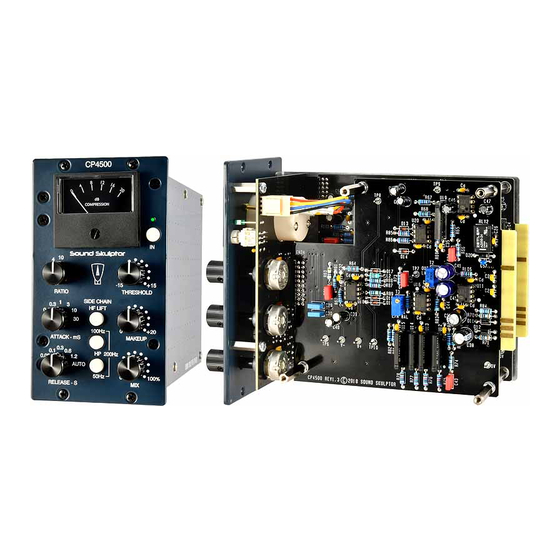
Description
Remove CP4500 cover and the top PCB (B), leaving only PCB-C (front panel PCB) and
PCB-A in place.
Remove all other modules from your 500 rack or Lunchbox and insert the CP4500 into
the leftmost slot.
Connect the lower PCB (PCB-A) to your XT500.
Set RATIO to 10,
Set ATTACK to 0.1 mS,
Set RELEASE to 1.2 S,
Set THRESHOLD to +15,
Set MAKEUP to 0,
Set MIX to 100%
Set all the push switches in the up position.
Set your DMM to DC Volts on a 20 V scale.
Connect the black probe to test point 0V.
Power up the lunchbox.
Connect the red probe to test point V+. Check that you get a value between +15 and
+16 Volts.
Connect the red probe to test point V-. Check that you get a value between -15 and -16
Volts.
Connect the red probe to test point +12V. Check that you get a value between +11.5
and +12.5 Volts.
Connect the red probe to test point -12V. Check that you get a value between -11.5
and -12.5 Volts.
Press the IN switch and check that the front panel LED and meter light up.
Document revision 1.1 – Last modification : 06/02/19
www.soundskulptor.com
Advertisement
Table of Contents

Related Manuals for Sound Skulptor CP4500


Summary of Contents for Sound Skulptor CP4500
- Page 1 2 (PCB-B). If you own an XT500 connector extension, you can use it for the channel 1 setup. Before setup Remove CP4500 cover and the top PCB (B), leaving only PCB-C (front panel PCB) and PCB-A in place. Board installation...
- Page 2 You can use your multitrack software (DAW) to play a sine tone like the one that is downloadable from the “Support/Downloads & Useful links” section on our website. Connect your DMM to the CP4500 output, between pin 2 and pin 3 of the XLR. The DMM is set to AC Voltage.
Need help?
Do you have a question about the CP4500 and is the answer not in the manual?
Questions and answers