Table of Contents
Advertisement
Quick Links
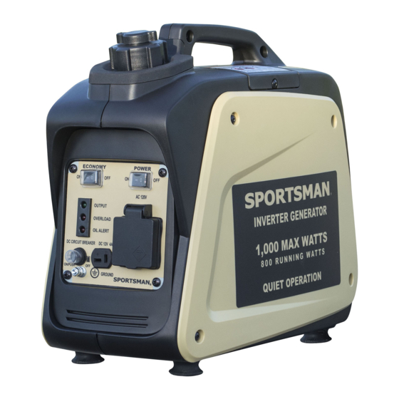
ITEM # GEN1000I-SS
1,000 SURGE WATTS / 800 RUNNING WATTS
GASOLINE INVERTER GENERATOR
INSTRUCTION MANUAL
R E A D A L L I N S T R U C T I O N S A N D W A R N I N G S B E F O R E U S I N G T H I S P R O D U C T .
This manual provides important information on proper operation & maintenance. Every effort has been made to ensure the
accuracy of this manual. These instructions are not meant to cover every possible condition and situation that may occur. We
reserve the right to change this product at any time without
prior notice.
I F T H E R E I S A N Y Q U E S T I O N AB O U T A C O N D I T I O N B E I N G S A F E O R U N S A F E , D O N O T
O P E R A T E T H I S P R O D U C T !
If you experience a problem, have questions or need parts for this product, call Customer Service at 1-866-460-9436, Monday-
Friday, 8 AM - 4 PM Central Time. A copy of the sales receipt is required.
FOR CONSUMER USE ONLY – NOT FOR PROFESSIONAL USE.
KEEP THIS MANUAL, SALES RECEIPT & APPLICABLE WARRANTY FOR FUTURE REFERENCE.
CALIFORNIA PROPOSITION 65
WARNING: This product, or the exhaust from this generator, may contain chemicals, including lead, known to the State of
California to cause cancer and birth defects or other reproductive harm. Wash hands after handling.
1
Advertisement
Table of Contents

Related Manuals for Buffalo Tools GEN1000I-SS


Summary of Contents for Buffalo Tools GEN1000I-SS
- Page 1 ITEM # GEN1000I-SS 1,000 SURGE WATTS / 800 RUNNING WATTS GASOLINE INVERTER GENERATOR INSTRUCTION MANUAL R E A D A L L I N S T R U C T I O N S A N D W A R N I N G S B E F O R E U S I N G T H I S P R O D U C T .
- Page 2 FEATURES: Included with this Generator: • 1000 Surge Output / 800 Running Watts* • DC connector wires for connecting 12 Volt • 120V Operation automotive-type batteries • 1.3 HP Engine, 4 Stroke , 5500 RPM • Spark plug wrench • Displacement (CC): 40cc •...
-
Page 3: Important Safety Instructions
IMPORTANT SAFETY INSTRUCTIONS STOP! Before using this generator and if you have any questions regarding the hazard and safety notices listed in this manual and/or on this generator, call 1-866-460-9436, Monday - Friday, 8 AM - 4 PM Central Time. Carbon Monoxide Gas: When in operation, the exhaust from this generator contains poisonous carbon monoxide gas. - Page 4 This generator produces powerful voltage, which can result in electrocution. Powerful Voltage: • ALWAYS ground this generator before using it. (See “Ground the Generator” section in this manual). • Only electrical devices should be plugged into this generator, either directly or with an extension cord. NEVER connect a building electrical system to this generator without a qualified electrician.
- Page 5 Misuse of this generator can damage it or shorten its life. Usage: • Use this generator only for its intended purpose. • Operate this generator only on a dry, level surface. Do not secure the generator with a chain or rope, which would prevent it from being moved in an emergency.
-
Page 6: Engine Switch
DESCRIPTION (1) Economy control switch (2) Engine switch (3) Fuel tank (4) Spark plug (5) Muffler (6) Carrying handle (7) Choke lever (8) AC pilot light (9) Overload indicator light (10) Oil warning light (11) Ground (earth) terminal (12) DC protector (13) DC receptacle (14) AC receptacle (16) Fuel filter... -
Page 7: Overload Indicator Light
3) LOW OIL ALERT SENSOR When the oil level falls below the acceptable level, the engine stops automatically. Unless you refill with oil, the engine will not start again. 4) OVERLOAD INDICATOR LIGHT The overload indicator light comes on when an overload of a connected electrical device is detected, the inverter unit overheats, or the AC output voltage rises. -
Page 8: Check Engine Oil
CHECK ENGINE OIL Remove side panel, remove oil filler cap and check the engine oil level. Make sure the engine oil is at the upper level of the oil filler hole. l WARNING: The generator has been shipped without engine oil. Fill with oil or it will not start. Do not tilt the generator when adding engine oil. - Page 9 DC APPLICATION This usage is applicable to 12V battery charging. Be sure the Economy Control Switch is turned off while charging the battery. STOPPING T HE E NGINE Turn off the power switch of the electric apparatus or disconnect any electric devices.
-
Page 10: Engine Oil Replacement
System Check muffl e r screen. l Cl e an / repl a ce i f necessary. Carburetor Check choke operati o n l Cool i n g Check fan damage. l system Starti n g Check recoi l starter operati o n. l... -
Page 11: Cleaning And Adjusting Spark Plug
WASHABLE AIR FILTER Maintaining an air cleaner in proper condition is very important. Dirt induced through improperly installed, improperly serviced, or inadequate elements damages and wears out engines. Keep the element always clean. 1. Remove the cover. 2. Remove the air filter cover and element. 3. -
Page 12: Troubleshooting
TROUBLESHOOTING Engine won’t start 1. Fuel system: No fuel supplied to combustion chamber. l No fuel in tank …. Add fuel. Fuel in tank …. Fuel tank cap air vent knob to “OPEN”, fuel cock knob to “OPEN”. l l Clogged fuel line …. - Page 13 SPECIFICATION MODEL GEN1000I-SS Type Invertor Generator AC Voltage 60Hz 120V Max. Output 1.00 kVA Rated Output 0.80 kVA Power Factor DC Output 12V / 4.0A Model XY139F-6 Type Air-cooled, 4 cycle, OHV, Gasoline Engine Bore×Stroke mm×mm 39×33.5 Displacement 40 cc Max.
-
Page 14: Storage Instructions
STORAGE INSTRUCTIONS Long t erm s torage o f y our m achine w ill r equire s ome p reventive p rocedures t o g uard a gainst d eterioration. 1. ... -
Page 15: Wiring Diagram
WIRING DIAGRAM 15 ... - Page 16 16 ...
- Page 17 17 ...
- Page 18 18 ...
- Page 19 19 ...
- Page 20 20 ...
- Page 21 21 ...
- Page 22 22 ...
- Page 23 23 ...
- Page 24 EMISSION C ONTROL S YSTEM W ARRANTY BUFFALO C ORPORATION Your Warranty Rights and Obligations The California Air Recourse Board, U.S. EPA and Buffalo Corp. are pleased to explain the Emission Control System Warranty on your 2019 model year new outdoor power equipment engine.
- Page 25 Owner’s Warranty Responsibility As the power equipment engine owner, you are responsible for the performance of the required maintenance listed in your owner’s manual. BUFFALO CORP. recommends that you retain all receipts covering maintenance on your power equipment engine, but BUFFALO CORP. cannot deny warranty solely for the lack of receipts or for your failure to ensure the performance of all scheduled maintenance.
- Page 26 Corp. According to Subsection (4) below. Any such part repaired or replaced under warranty will be warranted for the remainder of the period prior to the first scheduled replacement point for the part. Repair or replacement of any warranted part under the warranty provisions herein must be performed at a warranty station at no charge to the owner. Notwithstanding the provisions herein, warranty services or repair will be provided at all of our distribution centers that are franchised to service the subject engines.
- Page 27 EMISSION WARRANTY PARTS LIST (1) Fuel Metering System: (a) Gasoline carburetor assembly and its internal components (b) Carburetor gaskets (c) Fuel line (d) Clamps (e) Fuel tank (f) Fuel line fittings (g) pressure regulator (if equipped) (h) Mixer assembly and its internal components (if equipped) (2) Air induction system including: (a) Intake pipe/manifold (b) Air cleaner (3) Ignition system including: (a) Spark plug (b) Ignition coil...
Need help?
Do you have a question about the GEN1000I-SS and is the answer not in the manual?
Questions and answers