Table of Contents
Advertisement
Quick Links
Advertisement
Table of Contents

Related Manuals for Clevo M590KE


Summary of Contents for Clevo M590KE
- Page 1 All manuals and user guides at all-guides.com...
- Page 2 All manuals and user guides at all-guides.com...
- Page 3 All manuals and user guides at all-guides.com Preface Notebook Computer M590KE Service Manual...
- Page 4 All manuals and user guides at all-guides.com Preface Notice The company reserves the right to revise this publication or to change its contents without notice. Information contained herein is for reference only and does not constitute a commitment on the part of the manufacturer or any subsequent ven- dor.
- Page 5 All manuals and user guides at all-guides.com Preface About this Manual This manual is intended for service personnel who have completed sufficient training to undertake the maintenance and inspection of personal computers. It is organized to allow you to look up basic information for servicing and/or upgrading components of the M590K series notebook PC.
- Page 6 All manuals and user guides at all-guides.com Preface IMPORTANT SAFETY INSTRUCTIONS Follow basic safety precautions, including those listed below, to reduce the risk of fire, electric shock and injury to per- sons when using any electrical equipment: 1. Do not use this product near water, for example near a bath tub, wash bowl, kitchen sink or laundry tub, in a wet basement or near a swimming pool.
- Page 7 All manuals and user guides at all-guides.com Preface Instructions for Care and Operation The notebook computer is quite rugged, but it can be damaged. To prevent this, follow these suggestions: 1. Don’t drop it, or expose it to shock. If the computer falls, the case and the components could be damaged. Do not expose the computer Do not place it on an unstable Do not place anything heavy...
- Page 8 All manuals and user guides at all-guides.com Preface 4. Avoid interference. Keep the computer away from high capacity transformers, electric motors, and other strong mag- netic fields. These can hinder proper performance and damage your data. 5. Take care when using peripheral devices. Use only approved brands of Unplug the power cord before peripherals.
- Page 9 All manuals and user guides at all-guides.com Preface Battery Precautions • Only use batteries designed for this computer. The wrong battery type may explode, leak or damage the computer. • Do not continue to use a battery that has been dropped, or that appears damaged (e.g. bent or twisted) in any way. Even if the computer continues to work with a damaged battery in place, it may cause circuit damage, which may possibly result in fire.
- Page 10 All manuals and user guides at all-guides.com Preface Related Documents You may also need to consult the following manual for additional information: User’s Manual on CD This describes the notebook PC’s features and the procedures for operating the computer and its ROM-based setup pro- gram.
-
Page 11: Table Of Contents
LCD 20" (M590KE) ..............A-6 External Locator - Bottom View .............1-8 DVD DUAL (M590KE) ............... A-7 M590KE Mainboard Overview - Top (Key Parts) ......1-9 Combo Drive (M590KE) ............... A-8 M590KE Mainboard Overview - Bottom (Key Parts) ....1-10 HDD (M590KE) ................A-9 M590KE Mainboard Overview - Top (Connectors) .....1-11... - Page 12 All manuals and user guides at all-guides.com Preface PCI 7411, MCARD CON ............. B-21 PCMCIA SOCKET ..............B-22 HITACHI H8S/2111 ..............B-23 BIOS, CCD CON & FAN CON ........... B-24 SUPER I/O & FIR ................ B-25 AUDIO (ALC655), MDC ............B-26 SRS AP8202Q ................
-
Page 13: Introduction
1: Introduction Overview This manual covers the information you need to service or upgrade the M590KE series notebook computer. Information about operating the computer (e.g. getting started, and the Setup utility) is in the User’s Manual. Information about driv- ers (e.g. VGA & audio) is also found in User’s Manual. That manual is shipped with the computer. -
Page 14: System Specifications
All manuals and user guides at all-guides.com Introduction System Specifications Feature Specification µ Processor Types AMD Turion™ 64 X2 Mobile Technology Processor (31W) 0.09) 0.09 Micron Silicon-On-Insulator (SOI) Process 638-pin Micro-PGA-S1 Package Technology, 256KB * 2 L2 Cache Model TL-50 1.6GHz µ... - Page 15 All manuals and user guides at all-guides.com Introduction Feature Specification Storage Options Two Changeable Bays for 2.5" 9.5mm (h) Serial-ATA (SATA) Hard Disk Drives RAID 0, RAID 1, HDD Fault Tolerance System in SATA Configuration One Changeable Optical Device Bay - 12.7 mm (h) for Optical CD/DVD Device Drive Options (see“Optional”...
- Page 16 All manuals and user guides at all-guides.com Introduction Feature Specification Communication Infrared Transceiver 802.11 b/g USB Wireless LAN Module Infrared Transfer 1cm ~ 1M Operating Distance (Option) FIR/ IrDA 1.1 Compliant Bluetooth™USB 2.0 Module - Class II 10/100/1000 BASE-TX Fast Ethernet LAN (Factory Option) (PCIe Interface) 1.3M Pixel USB 2.0 PC Camera Module...
-
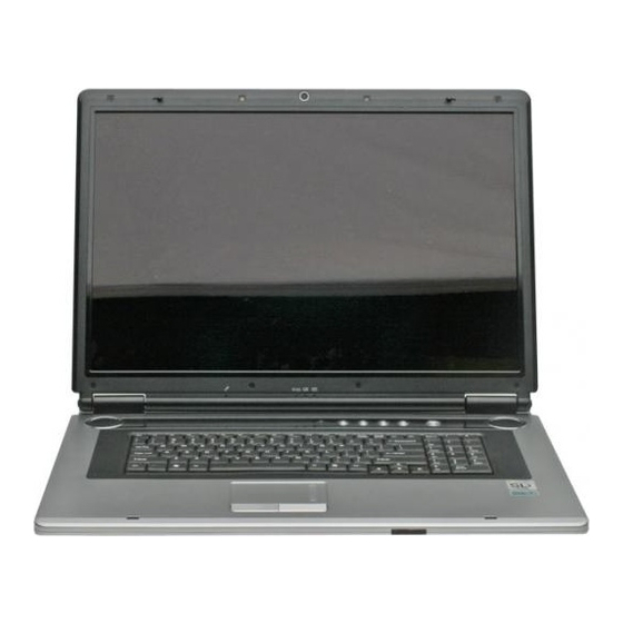
Page 17: External Locator - Top View With Lcd Panel Open
All manuals and user guides at all-guides.com Introduction External Locator - Top View with LCD Panel Open Figure 1 Top View 1. Optional Built-In PC Camera 2. LCD 3. LED Power & Communication Indicators 4. Speakers 5. AP-Key Buttons & Power Button 6. -
Page 18: External Locator - Front & Rear Views
All manuals and user guides at all-guides.com Introduction External Locator - Front & Rear Views Figure 2 Front &Rear Views LCD Latches Consumer Infrared Transceiver* 7-Pin S-Video-Out Jack DVI-Out Port DC-In Jack Vent/Fan Intake RJ-11 Phone Jack 2 * USB 2.0 Ports Serial Port 10. -
Page 19: External Locator - Left & Right Side View
All manuals and user guides at all-guides.com Introduction External Locator - Left & Right Side View Figure 3 Left Side View 1. S/PDIF-Out Jack 2. Line-In Jack 3. Microphone-In Jack 4. Headphone-Out Jack 5. Optical Device Drive Bay (for CD/ DVD Device) 6. -
Page 20: External Locator - Bottom View
All manuals and user guides at all-guides.com Introduction External Locator - Bottom View Figure 4 Bottom View 1. Battery 2. Battery Release Latch 3. CD/DVD Device Release Latch 4. Hard Disk Bay Cover 5. Vent/Fan Intake 6. Sub Woofer 7. Component Bay Cover 8. -
Page 21: M590Ke Mainboard Overview - Top (Key Parts)
1. KBC H8S/211 2. Sub Woofer 3. Audio ALC655 4. SRS AP8202Q 5. Ultra Media Card Bus PCI-7411 6. PC Card Assembly 7. VCORE 8. Super I/O PC87383 9. Infrared Transceiver M590KE Mainboard Overview - Top (Key Parts) 1 - 9... -
Page 22: M590Ke Mainboard Overview - Bottom (Key Parts)
3. CPU Socket (no CPU installed) 4. Memory Slots DDR2 SODIMM 5. TI ENE Card Controller 6. Mini Card Socket 7. Mini-PCIE Socket 8. NFORCE Crush K804 740BGA 9. Flash BIOS ROM 1 - 10 M590KE Mainboard Overview - Bottom (Key Parts) -
Page 23: M590Ke Mainboard Overview - Top (Connectors)
3. Fan (JFAN5) 4. Speaker-2 Cable (JSPK2) 5. Debug (JDEBUG2) 6. TouchPad (JTP1) 7. Keyboard Cable (JINTKB1) 8. Audio Cable (JAUDIO1) 9. RJ11 Board 10. Modem Module (JMDC1) 11. LED Cable (JLED1) M590KE Mainboard Overview - Top (Connectors) 1 - 11... -
Page 24: M590Ke Mainboard Overview - Bottom (Connectors)
9. Bluetooth Cable (J6) 10. Battery (JBAT1) 11. 40-Pin VGA Socket (CON4/CON2) 12. 30-Pin VGA Socket (CON1/CON3) 13. 160-Pin VGA Socket (CON5/ CON6) 14. Battery (JBAT1) 15. ODD (JCD1) 16. HDD (JHDD1/ JHDD2) 1 - 12 M590KE Mainboard Overview - Bottom (Connectors) -
Page 25: Disassembly
2: Disassembly Overview This chapter provides step-by-step instructions for disassembling the M590KE series notebook’s parts and subsystems. When it comes to reassembly, reverse the procedures (unless otherwise indicated). We suggest you completely review any procedure before you take the computer apart. -
Page 26: Maintenance Tools
All manuals and user guides at all-guides.com Disassembly NOTE: All disassembly procedures assume that the system is turned OFF, and disconnected from any power supply (the battery is removed too). Maintenance Tools The following tools are recommended when working on the notebook PC: •... -
Page 27: Maintenance Precautions
All manuals and user guides at all-guides.com Disassembly Maintenance Precautions The following precautions are a reminder. To avoid personal injury or damage to the computer while performing a re- moval and/or replacement job, take the following precautions: Power Safety Warning 1. -
Page 28: Disassembly Steps
All manuals and user guides at all-guides.com Disassembly Disassembly Steps The following table lists the disassembly steps, and on which page to find the related information. PLEASE PERFORM THE DISASSEMBLY STEPS IN THE ORDER INDICATED. To remove the Battery: To remove the Wireless LAN Module: 1. -
Page 29: Removing The Battery
All manuals and user guides at all-guides.com Disassembly Removing the Battery Figure 1 Battery Removal 1. Turn the computer off, turn it over and remove the battery. 2. Slide latch towards the unlock symbol and hold it in place, and slide latch in the direction of the arrow. -
Page 30: Removing The Hard Disk Drive(S)
All manuals and user guides at all-guides.com Disassembly Removing the Hard Disk Drive(s) Figure 2 HDD Assembly The hard disk drive is mounted in a removable case and can be taken out to accommodate other 2.5" serial (SATA) hard Removal disk drives with a height of 9.5mm (h). -
Page 31: Removing The Optical (Cd/Dvd) Device
All manuals and user guides at all-guides.com Disassembly Removing the Optical (CD/DVD) Device Figure 3 Optical Device 1. Turn off the computer, and turn it over and remove the battery (page 2 - Removal 2. Slide latch towards the unlock symbol and hold it in place. Slide the optical device out of the computer at point a. -
Page 32: Removing The System Memory (Ram)
All manuals and user guides at all-guides.com Disassembly Removing the System Memory (RAM) Figure 4 RAM Module The computer has two memory sockets for 200 pin Small Outline Dual In-line (SO-DIMM) DDRII (DDR2) type memory Removal modules. The total memory size is automatically detected by the POST routine once you turn on your computer. 1. -
Page 33: Removing The Processor
All manuals and user guides at all-guides.com Disassembly Removing the Processor Figure 5 Processor Removal 1. Turn off the computer, and turn it over, remove the battery (page 2 - 5) and remove the component bay cover (page 2 - 2. - Page 34 All manuals and user guides at all-guides.com Disassembly 5. Turn the release latch towards the unlock symbol , to release the CPU. Figure 6 6. Carefully (it may be hot) lift the CPU up out of the socket (Figure e). Processor Removal 7.
-
Page 35: Removing The Vga Card(S)
All manuals and user guides at all-guides.com Disassembly Removing the VGA Card(s) Figure 7 VGA Card(s) 1. Turn off the computer, and turn it over, remove the battery (page 2 - 5) and remove the component bay cover (page 2 - Removal 2. -
Page 36: Removing The Wireless Lan Module
All manuals and user guides at all-guides.com Disassembly Removing the Wireless LAN Module Figure 8 Wireless LAN 1. Turn off the computer, and turn it over, remove the battery (page 2 - 5) and remove the component bay cover Module Removal (page 2 - 2. -
Page 37: Removing The Tv Tuner Card
All manuals and user guides at all-guides.com Disassembly Removing the TV Tuner Card Figure 9 TV Tuner Card 1. Turn off the computer, and turn it over, remove the battery (page 2 - 5) and remove the component bay cover Removal (page 2 - 2. -
Page 38: Removing The Bluetooth Module
All manuals and user guides at all-guides.com Disassembly Removing the Bluetooth Module Figure 10 Bluetooth Module 1. Turn off the computer, and turn it over, remove the battery (page 2 - Removal 1. The Bluetooth module bay cover is located under the battery. 2. -
Page 39: Removing The Keyboard
All manuals and user guides at all-guides.com Disassembly Removing the Keyboard Figure 11 Keyboard Removal 1. Turn off the computer, and remove the battery (page 2 - 2. Press the four keyboard latches at the top of the keyboard to elevate the keyboard from its normal position (you a. -
Page 40: Removing The Pc Camera Module
All manuals and user guides at all-guides.com Disassembly Removing the PC Camera Module Figure 12 PC Camera Removal 1. Turn off the computer, and remove the battery (page 2 - 2. Remove the rubber covers and screws from the front of the LCD assembly, then run your finger around the a. -
Page 41: Part Lists
Part Lists Appendix A: Part Lists This appendix breaks down the M590KE series notebook’s construction into a series of illustrations. The component part numbers are indicated in the tables opposite the drawings. Note: This section indicates the manufacturer’s part numbers. Your organization may use a different system, so be sure to cross-check any relevant documentation. -
Page 42: Part List Illustration Location
A - 3 Top - (M590KE) page A - 4 Bottom - (M590KE) page A - 5 LCD 19" - (M590KE) page A - 5 LCD 20" - (M590KE) page A - 6 DVD DUAL - (M590KE) page A - 8... -
Page 43: Top (M590Ke
Figure A - 1 無鉛 無鉛 Top (M590KE) 無鉛 無鉛 無鉛 無鉛 無鉛 無鉛 無鉛 無鉛 無鉛 無鉛 無鉛 無鉛 無鉛 無鉛 無鉛 無鉛 無鉛 無鉛 無鉛 無鉛 無鉛 無鉛 無鉛 無鉛 無鉛 無鉛 無鉛 無鉛 無鉛 無鉛 Top (M590KE) A - 3... -
Page 44: Bottom (M590Ke
無鉛 無鉛 無鉛 無鉛 無鉛 無鉛 無鉛 無鉛 無鉛 無鉛 無鉛 無鉛 無鉛 無鉛 無鉛 無鉛 無鉛 無鉛 (黑色)硬度:30度 無鉛 無鉛 無鉛 無鉛 無鉛 無鉛 無鉛 昆山 M590KE 無鉛 (外) 新盛力 無鉛 無鉛 無鉛 無鉛 A - 4 Bottom (M590KE) -
Page 45: Lcd 19" (M590Ke
Figure A - 3 無鉛 LCD 19" (M590KE) 無鉛 無鉛 無鉛 無鉛 無鉛 無鉛 無鉛 無鉛 無鉛 無鉛 無鉛 無鉛 無鉛 無鉛 無鉛 無鉛 無鉛 無鉛 無鉛 無鉛 中性 無鉛 無鉛 無鉛 無鉛 無鉛 無鉛 無鉛 無鉛 LCD 19" (M590KE) A - 5... -
Page 46: Lcd 20" (M590Ke
LCD 20" (M590KE) 無鉛 無鉛 無鉛 無鉛 無鉛 無鉛 無鉛 無鉛 無鉛 無鉛 無鉛 無鉛 無鉛 無鉛 無鉛 無鉛 無鉛 無鉛 惠貿 無鉛 無鉛 惠貿 無鉛 無鉛 中性 無鉛 無鉛 無鉛 無鉛 無鉛 無鉛 無鉛 無鉛 A - 6 LCD 20" (M590KE) -
Page 47: Dvd Dual (M590Ke
All manuals and user guides at all-guides.com Part Lists DVD DUAL (M590KE) Figure A - 5 DVD DUAL (M590KE) 無鉛 無鉛 無鉛 無鉛 無鉛 無鉛 無鉛 無鉛 無鉛 DVD DUAL (M590KE) A - 7... -
Page 48: Combo Drive (M590Ke
All manuals and user guides at all-guides.com Part Lists Combo Drive (M590KE) Figure A - 6 Combo Drive (M590KE) 無鉛 無鉛 無鉛 無鉛 無鉛 無鉛 A - 8 Combo Drive (M590KE) -
Page 49: Hdd (M590Ke
All manuals and user guides at all-guides.com Part Lists HDD (M590KE) Figure A - 7 HDD (M590KE) HDD (M590KE) A - 9... - Page 50 All manuals and user guides at all-guides.com Part Lists A - 10...
-
Page 51: Schematic Diagrams
All manuals and user guides at all-guides.com Schematic Diagrams Appendix B: Schematic Diagrams This appendix has circuit diagrams of the M590KE notebook’s PCB’s. The following table indicates where to find the appropriate schematic diagram. Diagram - Page Diagram - Page... -
Page 52: System Block Diagram
All manuals and user guides at all-guides.com Schematic Diagrams SYSTEM BLOCK DIAGRAM DDR2 SHEET 27 SO-DIMM M590KE Socket SHEET 9 SHEET 2,3,4,5,6 BLOCK Dual channel TV OUT SHEET 16 Hyper Transport SHEET DIAGRAM Link0 800Hz Min trace w idth=5 mils... -
Page 53: Npt 64 (P1) Hypertransport
All manuals and user guides at all-guides.com Schematic Diagrams NPT 64 (P1) HyperTransport +3VS 5,7,8,9,10,11,12,13,14,15,17,18,19,22,23,24,25,27,28,31,32,34,35 +1.2V_HT 5,10,15 VLDT +1.2V(1.14~1.26) 1500mA U53A Place close to Socket Place close to Socket SEC 1 OF 6 +1.2V_HT C971 C972 C973 C974 C975 C976 C968 V_HT0_A1 V_HT0_B1... -
Page 54: Npt 64 (P2) Ddr2_A
All manuals and user guides at all-guides.com Schematic Diagrams NPT 64 (P2) DDR2_A U53C MEM_A_DATA[0..63] MEM_A_DATA[0..63] MEM_A_DQM[7..0] SEC 3 OF 6 MEM_A_DQM[7..0] 7 MEMORY _A MEM_A_DATA63 AA12 MEM_A_DQM7 MA_DATA[63] MA_DM[7] MEM_A_DATA62 AB12 AB16 MEM_A_DQM6 MA_DATA[62] MA_DM[6] MEM_A_DATA61 MEM_A_DQM5 AA14 MA_DATA[61] MA_DM[5] MEM_A_DATA60 MEM_A_DQM4... -
Page 55: Npt 64 (P3) Ddr2_B
All manuals and user guides at all-guides.com Schematic Diagrams NPT 64 (P3) DDR2_B +1.8V 5,6,7,8,29 +0.9V 6,7,8,29 +3V 5,10,11,12,14,15,18,19,20,21,22,23,25,28,29,31,32 U53D MEM_B_DATA[0..63] MEM_B_DQM[7..0] SEC 4 OF 6 MEM_B_DATA[0..63] MEM_B_DQM[7..0] 8 MEMORY_B MEM_B_DATA63 MEM_B_DQM7 AD11 AD12 MB_DATA[63] MB_DM[7] MEM_B_DATA62 MEM_B_DQM6 AF11 AC16 MB_DATA[62] MB_DM[6] MEM_B_DATA61... -
Page 56: Npt 64 (P4) Misc
All manuals and user guides at all-guides.com Schematic Diagrams NPT 64 (P4) Misc +1.8V +1.2V_HT 2,10,15 U60D 7/12 Add C1177 for LVC power +1.8V 4, 6,7,8,29 74LVC08 +3V 10,11, 12,14,15, 18,19,20,21, 22,23,25, 28,29,31,32 +3VS 2,7, 8,9,10,11, 12,13,14,15,17,18,19, 22,23,24,25,27,28,31, 32,34,35 +VDD3 9, 14,17,19,23, 28,29,30 C1177 0.1UF_06 R923... -
Page 57: Npt 64 (P5) Power
All manuals and user guides at all-guides.com Schematic Diagrams NPT 64 (P5) Power VCORE 31 +1.8V 4,5,7,8,29 +0.9V 4,7,8,29 U53F SEC 6 OF 6 CPU VDD GROUND VSS1 VSS66 VCORE +1.8V AA11 VSS2 VSS67 AA13 VSS3 VSS68 VCOR E AA15 U53E VSS4 VSS69... -
Page 58: Ddr Sodimm 1
All manuals and user guides at all-guides.com Schematic Diagrams DDR SODIMM 1 +0.9V MEM_A_ODT1 +1.8V 4,5,6,8,29 MEM_A_CS1# RN40 C 1111 0.1UF_06 +3VS 2,5,8,9,10,11,12,13,14,15,17,18,19,22,23,24,25,27,28,31,32,34,35 8P4RX47 +0.9V 4,6,8,29 MEM_A_CAS# C 1112 0.1UF_06 MEM_A_CKE1 RN41 C 1116 0.1UF_06 MEM_A_ADD14 8P4RX47 MEM_A_ADD15 C 1115 0.1UF_06 SO-DIMM A MEM_A_ADD12... -
Page 59: Ddr Sodimm 2
All manuals and user guides at all-guides.com Schematic Diagrams DDR SODIMM 2 +0.9V 4,6,7,29 +0.9V +1.8V 4,5,6,7,29 +1.8V +0.9V +3VS 2,5,7,9,10,11,12,13,14,15,17,18,19,22,23,24,25,27,28,31,32,34,35 MEM_B_RAS# C1129 0.1UF_06 C1096 0.1UF_06 MEM_B_BANK1 8P4RX47 RN47 MEM_B_ADD0 C1130 0.1UF_06 MEM_B_CS1# C1097 0.1UF_06 MEM_B_CAS# RN48 C1131 0.1UF_06 MEM_B_ODT1 8P4RX47 C1132 0.1UF_06... -
Page 60: Lcd Con & Lcd Vcc
All manuals and user guides at all-guides.com Schematic Diagrams LCD CON & LCD VCC +VDD3 5,14,17,19,23,28,29,30 LCD Vcc Power trace >= 60mil +3VS 2,5,7,8,10,11,12,13,14,15,17,18,19,22,23,24,25,27,28,31,32,34,35 +5VS 12,15,17,19,22,23,25,27,28,29,32,33,34,35 +12V 5,20,21,23,25,27,28,29 +5V 14,16,17,19,21,22,23,28,31 8P4RX0 LVDSUCLKN LVDS_UCLKN 35 LVDSUCLKP LVDS_UCLKP 35 LVDSUN3 LVDS_UN3 35 LVDSUP3 LVDS_UP 3 35 8P4RX0... -
Page 61: Ck804 Ht Part A
All manuals and user guides at all-guides.com Schematic Diagrams CK804 HT Part A +1.2V_HT 2,5,15 +3V 5,11,12,14,15,18,19,20,21,22,23,25,28,29,31,32 +3VS 2,5,7,8,9,11,12,13,14,15,17,18,19,22,23,24,25,27,28,31,32,34,35 +VDD5 14,17,19,23,25,28,29,31,33,35 U4H1A MBGA740 CK804 L0_CADOUT_H[15..0] L0_CADIN_H[15..0] 2 L0_CADOUT_H0 AG30 L0_CADIN_H0 SEC 1 OF 7 HT_RXD0 HT_TXD0 L0_CADOUT_H1 AF30 L0_CADIN_H1 HT_RXD1 HT_TXD1 L0_CADOUT_H2 L0_CADIN_H2... -
Page 62: Ck804 Pci-E Part B
All manuals and user guides at all-guides.com Schematic Diagrams CK804 PCI-E Part B +1.5VS 15,19,32,33 +3V 5,10,12,14,15,18,19,20,21,22,23,25,28,29,31,32 +3VS 2,5,7,8,9,10,12,13,14,15,17,18,19,22,23,24,25,27,28,31,32,34,35 MBGA740 U4H1B PEG_RXP[0..15] PEG_TXP[0..15] PEG_RXP[0..15] 35 SEC 2 OF 7 PEG_TXP0 PEG_RXP0 PE0_RX0 PE0_TX0 PEG_TXP1 CK804 PEG_RXP1 PCIE route 5/5/20. PE0_RX1 PE0_TX1 PEG_TXP2 PEG_RXP2... -
Page 63: Ck804 Pci Part C
All manuals and user guides at all-guides.com Schematic Diagrams CK804 PCI Part C +3VS 2,5,7,8,9,10,11,13,14,15,17,18,19,22,23,24,25,27,28,31,32,34,35 +3V 5,10,11,14,15,18,19,20,21,22,23,25,28,29,31,32 +5VS 9,15,17,19,22,23,25,27,28,29,32,33,34,35 Shared bus to all PCI Device Route 5/5. U4H1C +3VS MBGA740 PCI_AD[0..31] 19,20 PCI_AD[0..31] SEC 3 OF 7 PCI_AD0 R292 PEX REFCLKIN FREQ PCI_AD0 PCI_REQ0/GPIO* PCI_REQ0# 20... -
Page 64: Ck804 Sata & Pata Part D
All manuals and user guides at all-guides.com Schematic Diagrams CK804 SATA & PATA Part D +3VS 2,5,7,8,9,10,11,12,14,15,17,18,19,22,23,24,25,27,28,31,32,34,35 U4H1D MBGA740 IDE_PDD[0..15] IDE_PDD[0..15] 34 route 7/12/30 max length 3000mils SEC 4 OF 7 AE20 IDE_PDD0 SATATXP0 SP_TXP0 IDE_DATA_P0 CK804 AA17 IDE_PDD1 SATATXN0 SP_TXN0 IDE_DATA_P1 IDE_PDD2... -
Page 65: Ck804 Codec, Usb, Io Part E
All manuals and user guides at all-guides.com Schematic Diagrams CK804 CODEC, USB, IO Part E +VDD5 10,17,19,23,25,28,29,31,33,35 Ma tch RXD[0..3] & Match TXD[0..3] & +VDD3 5,9,17,19,23,28,29,30 +3V 5,10,11,12,15,18,19,20,21,22,23,25,28,29,31,32 RXCTL signal to this TXCTL signal to this RGMII(Reduced Gigabit media indepentent I/F) +3VS 2,5,7,8,9,10,11,12,13,15,17,18,19,22,23,24,25,27,28,31,32,34,35 signal within 100mil. -
Page 66: Ck804 Power & Gnd Part F
All manuals and user guides at all-guides.com Schematic Diagrams CK804 Power & GND Part F +5VS +5VS +1.5VS 11,19,32,33 +5VS 9,12,17,19,22,23,25,27,28,29,32,33,34,35 +3V 5,10,11,12,14,18,19,20,21,22,23,25,28,29,31,32 +1.2V_HT 2,5,10 +3VS 2,5,7,8,9,10,11,12,13,14,17,18,19,22,23,24,25,27,28,31,32,34,35 RB751V RB751V CK804 DECOUPLING MBGA740 U4H1G +1.5VS +1.5VS SEC 7 OF 7 CK804 AH30 Z1401 +1.5V1... -
Page 67: Usb Con * 3, Tv-S Out
All manuals and user guides at all-guides.com Schematic Diagrams USB CON * 3, TV-S Out +5V 14,17,19,21,22,23,28,31 Vcc Power trace >= 60mil 6-21-B4900-104 JUSB1 Z1504 L_0805(159) USB_+5V-3 GND1 Z1505 GND2 7/21 USB Power from POLY SW to RT9701 USB_PN1 DATA- R265 GND3 C236... -
Page 68: Inv, Web, Click, S/W Con
All manuals and user guides at all-guides.com Schematic Diagrams INV, WEB, CLICK, S/W CON +5V 14,16, 19, 21,22,23,28,31 +5VS 9,12,15, 19, 22,23,25, 27,28,29,32,33,34,35 +3VS 2,5, 7,8,9,10, 11, 12,13,14,15,18,19,22,23,24,25,27, 28, 31,32,34, 35 LID SWITCH VI N 28,29, 30, 31,33,35 C140 10U_10V_1206 +VDD3 5, 9,14,19,23,28, 29,30 +3VS +VDD5 10,14, 19, 23,25,28,29,31,33,35... -
Page 69: Pci-E Lan (Realtech 8111B
All manuals and user guides at all-guides.com Schematic Diagrams PCI-E LAN (Realtech 8111B) +3V 5,10,11,12,14,15,19,20,21,22,23,25,28,29,31,32 LAN_AVDD3 LAN_VDD3 LANVDD15 7/12 R505 unstaff +3VS 2,5,7,8,9,10,11,12,13,14,15,17,19,22,23,24,25,27,28,31,32,34,35 LAN_VDD3 LANVDD15 R505 *10K_06 R506 3.6K_06 C1159 0.1UF_06 60 mil C1160 0.1UF_06 EECS C1161 0.1UF_06 EECS MA2/EESK LAN_AVDD18 AVDD18 EESK... - Page 70 All manuals and user guides at all-guides.com Schematic Diagrams MINIPCI (Tuner, WLAN, BT) PCI_AD[0..31] JANT3 5/30 change PCIE signal to PCIE1 12,20 PCI_AD[0..31] I-pad JANT1 +VDD3 +VDD3 5,9,14,17,23,28,29,30 JANT1_GND RP20 8P 4RX0 +3V 5,10,11,12,14,15,18,20,21,22,23,25,28,29,31,32 JANT3 PETP0 +3VS PE1_IN +3VS 2,5,7,8,9,10,11,12,13,14,15,17,18,22,23,24,25,27,28,31,32,34,35 JANT2_GND PETN0 PE1_IN#...
-
Page 71: Pci 7411, Mcard Con
All manuals and user guides at all-guides.com Schematic Diagrams PCI 7411, MCARD CON MS_SD_3V PCUVCC U30-1 PCI7411GHK VCC P +3V 5,10,11,12,14,15,18,19,21,22,23,25,28,29,31,32 R743 12,19 PCI_AD[0..31] +12V 5,9,21,23,25,27,28,29 VCC P 10K_06 NEW PART VR _1.5V 21 PC I_AD31 R 744 R 745 R 78 AD31 PC I_AD30... -
Page 72: Pcmcia Socket
All manuals and user guides at all-guides.com Schematic Diagrams PCMCIA SOCKET VCCCA VCCCA NEW PART VR_1.5V 20 +3V 5,10,11,12,14,15,18,19,20,22,23,25,28,29,31,32 +5V 14,16,17,19,22,23,28,31 U30-3 U30-2 VPPCA +12V 5,9,20,23,25,27,28,29 Z2111 GND1 T505 VCCB VCCA Z2112 CAD0 GND2 T506 VCCB VCCA D3 - CAD0 CAD1 GND3 D4 - CAD1... -
Page 73: Hitachi H8S/2111
All manuals and user guides at all-guides.com Schematic Diagrams HITACHI H8S/2111 +3V 5,10,11,12,14,15,18,19,20,21,23,25,28,29,31,32 +5VH8 +3VH8 H8MD_1 +3VS 2,5,7,8,9,10,11,12,13,14,15,17,18,19,23,24,25,27,28,31,32,34,35 +3VH8 +VDD3 5,9,14,17,19,23,28,29,30 +5V 14,16,17,19,21,23,28,31 Z2216 R320 10K_06 +5VS 9,12,15,17,19,23,25,27,28,29,32,33,34,35 +3VH8 Z2217 Z2218 H8_RESET# C351 C648 C300 C320 C279 R330 150K_06 +5VH8 27,28,29 RESET# +3VH8 +3VH8... -
Page 74: Bios, Ccd Con & Fan Con
All manuals and user guides at all-guides.com Schematic Diagrams BIOS, CCD CON & FAN CON +3VS +12V 5,9,20,21,25,27, 28,29 +5VS 9,12,15,17,19,22,25,27,28,29,32,33,34, 35 C701 0.01U_06 +5V 14,16,17,19, 21,22,28,31 +3VS 2,5,7, 8,9,10,11, 12,13,14,15,17, 18,19,22,24,25, 27,28,31,32,34, 35 C744 0.01U_06 +3V 5, 10,11,12,14,15, 18,19,20,21,22, 25,28,29,31,32 SOCKET PLCC32 +VDD3 5,9,14,17,19,28, 29, 30 7/12 change R733 component &... -
Page 75: Super I/O & Fir
All manuals and user guides at all-guides.com Schematic Diagrams SUPER I/O & FIR +3VS +3VS 2,5,7,8,9,10,11,12,13,14,15,17,18,19,22,23,25,27,28,31,32,34,35 +3V 5,10,11,12,14,15,18,19,20,21,22,23,25,28,29,31,32 FIRVCC L_0805(159) 4.7U_0805 +3VS FIRGND 8P4RX18 8P4RX18 *4.7K_06 47K_06 Z2504 FIRGND 1000P_06 +3VS RP6-NC1 RP6-NC2 LPC_AD1 HSDL-360 IRRX RP6-NC3 LPC_AD0 LPC_AD3 LPC_DRQ#0 IRMODE U3-MD0 LPC_AD2... -
Page 76: Audio (Alc655), Mdc
All manuals and user guides at all-guides.com Schematic Diagrams AUDIO (ALC655), MDC Vcc Power trace >= 60mil +5VS AUD_5VS +5VS 9, 12, 15,17,19,22,23,27,28,29,32,33,34, 35 C619 C618 +3V 5,10,11,12,14,15,18,19, 20, 21,22, 23,28,29,31,32 PLEASE PLACE CLOSE CODEC & +3VS 2, 5,7,8,9,10, 11,12, 13, 14,15,17,18,19,22,23,24,27,28,31, 32, 34,35 1UF/10V_06 *1UF/10V_06 AMP THE POWER INPUT PINS... -
Page 77: Srs Ap8202Q
All manuals and user guides at all-guides.com Schematic Diagrams SRS AP8202Q AUDIO PROCESSOR PRE-AMP AUD_VDD 17,25 R318 *0_06 *0_06 R297 7/12 C632 fix value to meet BOM C296 1UF/10V_06 Z2701 Z2729 R 562 0_06 17,25 FRONT-L LOU T PRE_LOUT 25 C284 1UF/10V_06 Z2702... -
Page 78: Sub Woofer, Dvi Con
All manuals and user guides at all-guides.com Schematic Diagrams SUB WOOFER, DVI CON +5VS +5VS 9,12,15,17,19,22,23,25,28,29,32,33,34,35 +12V +12V 5,9,20,21,23,25,28,29 +5VH8 +5VH8 22,28,29 +3VS +3VS 2,5,7,8,9,10,11,12,13,14,15,17,18,19,22,23,24,25,28,31,32,34,35 AUD_VDDA1 Z2813 R339 10K _06 C657 270P_06 AUD_AGND C651 C263 C628 C658 C633 Truth table 0.1UF_06 0.1UF_06 0.1UF_06... -
Page 79: 5Vs, +3Vs, +5V, +3V
All manuals and user guides at all-guides.com Schematic Diagrams +5VS, +3VS, +5V, +3V VAD 22,30 +VDD3 VA 30 +VDD3 5,9,14,17,19,23,29,30 VIN 17,29,30,31,33,35 +3VH 8 22 VIN1 29,35 +3V 5,10,11,12,14,15,18,19,20,21,22,23,25,29,31,32 +12V 5,9,20,21,23,25,27,29 +3VS 2,5,7,8,9,10,11,12,13,14,15,17,18,19,22,23,24,25,27,31,32,34,35 PR29 +5VH8 22,27,29 +1.5VS 11,15,19,32,33 1K_06 PQ23 +5V 14,16,17,19,21,22,23,31 +VDD5 10,14,17,19,23,25,29,31,33,35 +3VS... -
Page 80: Vdd5, +Vdd3, +3V, +5V, +1.25V
All manuals and user guides at all-guides.com Schematic Diagrams +VDD5, +VDD3, +3V, +5V, +1.25V VIN 17,28, 30,31,33,35 +VDD5A VIN 1 28,35 PQ39 0.7A +12V+ +12V +12V 5,9,20, 21,23,25,27,28 AO3409 PC59 10U_25V_1206 Z3016 +5VS 9,12,15,17,19,22,23,25,27,28,32,33,34, 35 6. 8uH SM140A +5VH8 22,27,28 +VDD5 10,14,17,19,23,25, 28,31,33,35 PC103 0.01U_06... -
Page 81: Charger, Bat Con, Pwr Con
All manuals and user guides at all-guides.com Schematic Diagrams CHARGER, BAT CON, PWR CON Allen_20060421 VAD 22,28 EMI Rule VA 28 VIN 17, 28,29, 31,33, 35 +VDD3 +VDD 3 5,9, 14,17,19,23,28,29 SI4835BDY 5/30 PR115 meet BOM H CB4532K-800(1812) PR109 40m_2512 EMI Rule 40m_2512 C840... -
Page 82: Vcore
All manuals and user guides at all-guides.com Schematic Diagrams VCORE 8/3 Add PC205, PC206 for VIN noise 8/3 Add PQ72 PQ73 for thermal issue CPU_VID0 PR136 CPU_VID0 CPU_VID1 1K_06 CPU_VID1 PC130 PC131 PC132 PC133 PC205 PC206 CPU_VID2 PC134 PR137 10U_25V_1206 10U_25V_1206 10U_25V_1206 22U_25V_OS10*5... -
Page 83: Power Good
All manuals and user guides at all-guides.com Schematic Diagrams POWER GOOD +5VS 9,12,15,17,19,22,23,25,27,28,29,33,34,35 +3V 5,10,11,12,14,15,18,19,20,21,22,23,25,28,29,31 C900 0.1UF_06 +3VS +3VS 2,5,7,8,9,10,11,12,13,14,15,17,18,19,22,23,24,25,27,28,31,34,35 +1.5VS 11,15,19,33 C901 0.1UF_06 C904 C905 C906 C907 +3VS 0.1UF_06 0.1UF_06 0.1UF_06 0.1UF_06 C902 0.1UF_06 +3VS C903 0.1UF_06 +3VS NOTE: POWER SEQUENCING +3VS CK8_PWRGD Faster than PWRGD_SB. - Page 84 All manuals and user guides at all-guides.com Schematic Diagrams +1.5VS 5/30 PC89 change BOM level C422 C407 C425 PC89 C424 C426 VIN 17,28,29,30,31,35 +VDD5 +VDD5 10,14,17,19,23,25,28,29,31,35 2.2U_1206 *10U_1206 2.2U_1206 10U_25V_DIP 0.1UF_06 0.01U_06 +5VS 9,12,15,17,19,22,23,25,27,28,29,32,34,35 R433 10_06 +1.5VS 11,15,19,32 +5VS R633 08-10692-2D0 R632 1SS355...
-
Page 85: Sata Hdd & Cdrom
All manuals and user guides at all-guides.com Schematic Diagrams SATA HDD & CDROM +5VS 9,12,15,17,19,22,23,25,27,28,29,32,33,35 +3VS 2,5,7,8,9,10,11,12,13,14,15,17,18,19,22,23,24,25,27,28,31,32,35 SLAVE 5/30 Change STAT connector signal MASTER JHDD1 Place 0.01U ca ps at connector. JHDD2 Place 0.01U ca ps at conne ctor. Z3501 C516 0.01U_06 SATATXP2 13... -
Page 86: Vga Board Connector
All manuals and user guides at all-guides.com Schematic Diagrams VGA Board Connector VIN1 28,29 Slaver VIN 17,28,29,30,31,33 Z36142 PEG_TXN[0..15] +VDD5 10,14,17,19,23,25,28,29,31,33 T346 PEG_TXN[0..15] 11 Master Z36143 +5VS 9,12,15,17,19,22,23,25,27,28,29,32,33,34 6-21-C2Q10-280 T347 PEG_TXP[0..15] +3VS 2,5,7,8,9,10,11,12,13,14,15,17,18,19,22,23,24,25,27,28,31,32,34 PEG_TXP[0..15] 11 6-21-C2Q10-280 Master 6-20-C2D40-220 CON6 PEG_RXN[0..15] PEG_RXN[0..15] 11 Z36104 Z36144... -
Page 87: Click Board
M-MARK1 T756 CTP_RS_L T757 CTP_RS_D T758 TPBUTTON_L T759 CON12_85201-1205 Synaptic Touchpad 12 pin connector VENDOR PART NUMBER : 800504-2602 CLEVO PART NUMBER : Not apply C+5V 20-94A10-104 T760 CTP_DATA T761 CTP_CLK R-A/F 1.0mm UP T762 T763 CON1 CGND Click Board Connect TO MB. -
Page 88: Hot Key Board
All manuals and user guides at all-guides.com Schematic Diagrams HOT KEY BOARD HOT KEY BOARD BT SWITCH EMAIL SWITCH WWW SWITCH WLAN SWITCH CCD SWITCH PWR SWITCH HSW3 HSW4 HSW2 HSW1 HSW5 HWEB1# HWEB0# HWLAN_SW# HCCD_SW# HM_BTN# HCH_STS-02 HCH_STS-02 HCH_STS-02 *HCH_STS-02 HCH_STS-02 VGA SPEED SWITCH... -
Page 89: Phone Jack Board
All manuals and user guides at all-guides.com Schematic Diagrams PHONE JACK BOARD 20-B4040-006 UJSPDIF1 Z3901 AU DIO_JACK T781 Z3902 T782 PHONE JACK BOARD Z3903 T783 Z3904 L_0603(129) T784 USPDIF1 Z3905 75_06 680P_06 T785 SPDIF OUT UGND 1/20 VIN Pin1 Inverter. 20-B4040-006 UJLINEIN1 Z3906... -
Page 90: Rj11 Board
All manuals and user guides at all-guides.com Schematic Diagrams RJ11 BOARD M+3VS M+3VS MMDCC1 MJMODEM1 RJ11 BOARD L_0805(123) GND2 RJ11 MGND Z4005 Z4007 Z4006 Z4008 RING BAV99 BAV99 GND1 MGND1 L_0805(123) 85204-2 MS_IOC MS_IOY PIN GND1 T813 MGND =HGND1 6/23 JSVIDEO1 BOM error PIN GND2 =HGND 6-20-92K00-226... -
Page 91: Cd-Rom Board
All manuals and user guides at all-guides.com Schematic Diagrams CD-ROM BOARD +5VCDROM_DD DVD DRV REAR VIEW MASTER TO CDROM DDJCD2 INT_CD_R_1 INT_CD_L_1 Z4108 CD_GND_1 CDD[8]_1 CRESETN_1 CDD[9]_1 CDD[7]_1 CDD[10]_1 CDD[6]_1 CDD[11]_1 CDD[5]_1 CDD[12]_1 CDD[4]_1 CDD[13]_1 CDD[3]_1 CDD[14]_1 CDD[2]_1 CDD[15]_1 CDD[1]_1 CDMARQ_1 CDD[0]_1 CDIORN_1... -
Page 92: 2Nd Cd-Rom Board
All manuals and user guides at all-guides.com Schematic Diagrams 2nd CD-ROM BOARD SGND_DD SGND_DD +5VCDROM_DDD DVD DRV REAR VIEW MASTER TO CDROM DDJCD3 SINT_CD_R_1 SINT_CD_L_1 SZ4108 SCD_GND_1 SCDD[8]_1 SCRESETN_1 SCDD[9]_1 SCDD[7]_1 SCDD[10]_1 SCDD[6]_1 SCDD[11]_1 SCDD[5]_1 SCDD[12]_1 SCDD[4]_1 SCDD[13]_1 SCDD[3]_1 SCDD[14]_1 SCDD[2]_1 SCDD[15]_1 SCDD[1]_1... -
Page 93: Cir Board
All manuals and user guides at all-guides.com Schematic Diagrams CIR BOARD CIR+VDD5 C.IR GND2 GND2 C859 10U/10V_0805 GND1 GND1 C858 0.1UF_06 CIR_GND CIR_GND Sheet 44 of 46 CIR BOARD CIR+VDD5 JCIR2 CCIR_RX ACES_85204-0300 CIR_GND C27 6D107 CIR_GND CIR BOARD B - 43... -
Page 94: Flash Board
All manuals and user guides at all-guides.com Schematic Diagrams FLASH BOARD 20-51100-110 F+3V JDDEBUG1 F+3V FLASH_MD FUD1 TXDD11 Z4201 FCD1 0.1UF_06 RXDD11 DTR#D11 Z4202 4.7K_06 4.7K_06 4.7K_06 80CLOCK-D Z4205 FCD3 0.47U FCD13 FCD14 80DATA-D FCD2 0.47U Z4203 0.1UF_06 0.1UF_06 1000P DETECT Z4204 Z4206... -
Page 95: Debug Board
All manuals and user guides at all-guides.com Schematic Diagrams DEBUG BOARD D+5VS D+5VS D+5VS DJ80DEBUG1 0.1UF_06 0.1UF_06 0.1UF_06 0.1UF_06 10U_10V_1206 10U_10V_1206 10U_10V_1206 10U_10V_1206 80DATA-FH 80CLK-FH LPCDETECT 85205-5 D+5VS D+5VS D+5VS D+5VS D+5VS D+5VS D+5VS D+5VS D+5VS D+5VS 80DATA-FH Z4302 DR10 *LED_R *LED_R *LED_R... - Page 96 All manuals and user guides at all-guides.com Schematic Diagrams B - 46...
Need help?
Do you have a question about the M590KE and is the answer not in the manual?
Questions and answers