Table of Contents
Advertisement
Quick Links
Advertisement
Table of Contents

Related Manuals for Neptune Technology TRICON SmartTrol


Summary of Contents for Neptune Technology TRICON SmartTrol
- Page 1 ® TRICON SmartTrol™ Installation and Maintenance Guide...
- Page 3 ® TRICON SmartTrol™ Installation and Maintenance Guide...
- Page 4 This manual is an unpublished work and contains the trade secrets and confidential information of Neptune Technology Group Inc., which are not to be divulged to third parties and may not be reproduced or transmitted in whole or part, in any form or by any means, electronic or mechanical, for any purpose, without the express written permission of Neptune Technology Group Inc.
-
Page 5: Table Of Contents
Contents Chapter 1: Introduction Chapter 2: Typical Application Chapter 3: Operating the SmartTrol™ Display Total Display Grand Total Display Rate Setup the SmartTrol™ Chapter 4: General Description and Principles of Operation Display Resets Presets Relays K Factor Ratemeter Counter Lockout RS-232C Communications 4-20 mA Output Entering Decimal Points... - Page 6 Contents Fractional Units of Volume Changing Units of Volume Datalost Reset to Zero or Set to Preset Automatic or Manual Reset Decimal Location Ratemeter K Factor A and K Factor B (Rate) Changing Units of Times Changing Units of Volume Weight Window Significant Figures...
- Page 7 Contents Example: Unit Number 1 Chapter 12: Warranty Chapter 13: Assistance By Phone By Email Appendix A: Specifications ® TRICON/E Performance Data ® Trident Turbine Performance Data HP Turbine Performance Data DISC Elements in Compound Meters ® TRU/FLO Compound Meter (Turbine Side) ®...
- Page 8 Contents This page intentionally left blank ® ™ TRICON SmartTrol Installation and Maintenance Guide...
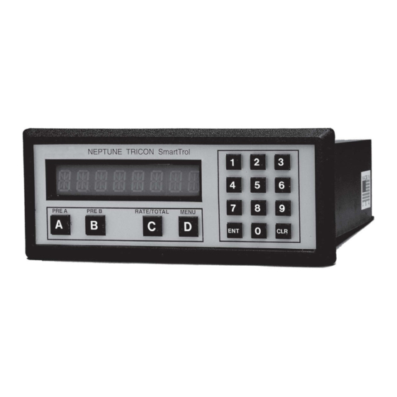
- Page 9 Figures ® Figure 1 – TRICON SmartTrol™ ® Figure 2 – SmartTrol™ to Power Single TRICON/E Transmitter Figure 3 – SmartTrol™ Dimensions ® Figure 4 – SmartTrol™ and Single TRICON/E Transmitter (Pulse Output and Remote Reset) Figure 5 – SmartTrol™ and Two TRICON/E ®...
- Page 10 Figures This page intentionally left blank. ® viii ™ TRICON SmartTrol Installation and Maintenance Guide...
- Page 11 Tables Table 1 – Display Total Table 2 – Display Grand Total Table 3 – Return to Total Table 4 – Display Rate Table 5 – Return to Total Table 6 – Specifications Table 7 – Example Programming Worksheet Table 8 – Setting Up the Counter Table 9 –...
- Page 12 Tables Table 31 – Accepting Current Register Reading Table 32 – Enter Current Register Reading Table 33 – Incrementing Total ® ™ TRICON SmartTrol Installation and Maintenance Guide...
-
Page 13: Chapter 1: Introduction
Chapter 1: Introduction The Neptune ® SmartTrol™ is a versatile microprocessor-based controller for use with ® TRICON/E electronic registers. The main functions of the unit are to: Display rate and totalization values. Control relays for batching or alarming. The SmartTrol allows two meter flows to be measured, separately scaled for both rate and total, then combined into one overall rate and total. - Page 14 Chapter 1: Introduction This page intentionally left blank. ® ™ TRICON SmartTrol Installation and Maintenance Guide...
-
Page 15: Chapter 2: Typical Application
Chapter 2: Typical Application ® In the following illustration, the SmartTrol™ powers a single TRICON/E transmitter that provides digital pulses to the SmartTrol. The SmartTrol scales the pulse input to determine rate of flow and total quantity through the meter. The SmartTrol uses the rate of flow or total values to operate two relays. - Page 16 Chapter 2: Typical Application This page intentionally left blank. ® ™ TRICON SmartTrol Installation and Maintenance Guide...
-
Page 17: Chapter 3: Operating The Smarttrol
Chapter 3: Operating the SmartTrol™ When you power on the SmartTrol™, it is in the normal operating mode. You can view Total, Grand Total, and Rate. To view Total, Grand Total, or Rate, apply power to one of the following displays. Display Total When you power on the SmartTrol, the current value of Total is displayed as indicated. -
Page 18: Display Rate
Chapter 3: Operating the SmartTrol™ Press the key indicated in the table to return to the Total. Table 3 – Return to Total Press Display Description ######## Current value of Total. Display Rate When Rate is displayed, the first character position on the display is “R”. Rate represents the volume of liquid passing through the meter in a unit of time (for example: gallons per minute). -
Page 19: Chapter 4: General Description And Principles Of Operation
Chapter 4: General Description and Principles of Operation This chapter provides a general description and the operating principles of the ® TRICON SmartTrol™. Display The SmartTrol shows one of three different variables on its eight-digit, alphanumeric displays: Total - the volume through the meter in gallons, cubic feet, or cubic meter units. Grand Total - similar to Total but continues to count when Total is reset. -
Page 20: Relays
Chapter 4: General Description and Principles of Operation Relays The SmartTrol is used for monitoring or for control purposes, such as batching. There are two control relays in the SmartTrol whose operations are based on preset values of Rate, Total, or Grand Total. Each relay may be programmed to its own preset value. The presets can be programmed to allow two-stage stepping of a process providing precise control of a dispensing or blending application. -
Page 21: Rs-232C Communications
Chapter 4: General Description and Principles of Operation RS-232C Communications You can order the SmartTrol with RS-232C computer communications. This option allows the SmartTrol to communicate with virtually any computer that has an RS-232C serial communications port. You can use the computer to read or modify the data in the SmartTrol. - Page 22 Chapter 4: General Description and Principles of Operation This page intentionally left blank. ® ™ TRICON SmartTrol Installation and Maintenance Guide...
-
Page 23: Chapter 5: Specifications
Chapter 5: Specifications ® This chapter provides the specifications for the TRICON SmartTrol™. Table 6 – Specifications Specification Description Housing High-impact plastic case with NEMA 4X front panel. Dimensions See Figure 3 on page 13. Display 8-character, 0.55" high, 15-segment, red orange LED. Input Power 110 VAC +/–... - Page 24 Chapter 5: Specifications This page intentionally left blank. ® ™ TRICON SmartTrol Installation and Maintenance Guide...
-
Page 25: Chapter 6: Mounting And Installation
Chapter 6: Mounting and Installation This chapter provides information on mounting and installing a SmartTrol™. Panel Mounting Mount the SmartTrol on any panel with a thickness between .047” (1.2 mm) and .187” (4.7 mm). It ships with two side mounting brackets, screws, and a panel gasket. The gasket fits between the SmartTrol bezel and the front panel to form a NEMA 4 splash-proof assembly when properly mounted. - Page 26 Chapter 6: Mounting and Installation This page intentionally left blank. ® ™ TRICON SmartTrol Installation and Maintenance Guide...
-
Page 27: Chapter 7: Connections To The Smarttrol
Chapter 7: Connections to the SmartTrol™ This chapter provides information on the various connections to the SmartTrol™. Power Connection For Alternating Current (AC) Be certain to remove all power from the wire before connecting the power wiring to the SmartTrol. Also be sure that the power is 120 VAC to prevent damage due to application of incorrect voltage. -
Page 28: Figure 4 - Smarttrol™ And Single Tricon/E
Chapter 7: Connections to the SmartTrol™ ® Figure 4 – SmartTrol™ and Single TRICON/E Transmitter (Pulse Output and Remote Reset) ® Figure 5 – SmartTrol™ and Two TRICON/E Transmitters (Pulse Output and Remote Reset) ® TRICON SmartTrol™ Installation and Maintenance Guide... -
Page 29: Figure 6 - Smarttrol™ And 4-20 Ma Tricon/E
Chapter 7: Connections to the SmartTrol™ The 24 VDC must power the 4-20 mA TRICON/E. The SmartTrol can produce 24 VDC by “stacking” two independent 12 VDC power supplies. Configure the SmartTrol to provide +24 VDC by tying the +12 VDC (PIN 15). This jumper causes +24 VDC to appear across PIN 16 referenced to ground (PIN 12). -
Page 30: Figure 7 - Smarttrol™ With 4-20 Ma Output Option And Smartchart And Single Tricon/E
Chapter 7: Connections to the SmartTrol™ Figure 7 – SmartTrol™ with 4-20 mA Output Option and SmartChart and ® Single TRICON/E Transmitter with Pulse Output ® TRICON SmartTrol™ Installation and Maintenance Guide... -
Page 31: Figure 8 - Smarttrol™ Powered By +24 Vdc, Relays Controlling +24 Vdc, And Single Tricon/E
Chapter 7: Connections to the SmartTrol™ An external DC power supply can power the SmartTrol. The supply must provide 12-27 VDC and at least 250 mA of current. Connect the positive side (+DC) of the supply to terminal 14 and the negative (or ground) side to terminal 12. Units Powered by DC voltage do not have an isolated voltage on terminals 15 and 16. -
Page 32: Figure 9 - Smarttrol™ And Single Tricon
Chapter 7: Connections to the SmartTrol™ ® Figure 9 – SmartTrol™ and Single TRICON /S Transmitter (Pulse Output and Remote Reset) Order the SmartTrol™ from the factory configured for use with the ® TRICON ® TRICON SmartTrol™ Installation and Maintenance Guide... - Page 33 Chapter 7: Connections to the SmartTrol™ Figure 10 – SmartTrol™ with 4-20 mA Output Option and Remote Device and Battery-Powered TRU/MAG™ ® ™ TRICON SmartTrol Installation and Maintenance Guide...
- Page 34 Chapter 7: Connections to the SmartTrol™ Figure 11 – SmartTrol™ with 4-20 mA Output Option and Remote Device and DC-Powered TRU/MAG™ ® TRICON SmartTrol™ Installation and Maintenance Guide...
-
Page 35: Chapter 8: Programming Worksheet
Chapter 8: Programming Worksheet This chapter provides an example of the programming worksheet. Table 7 – Example Programming Worksheet Configured By:__________________________________________________________ Date:________/________/________ Model Number:________________________________________________________ Application:_________________________________ Calculation Area:_______________________________________________________ COUNTER K Factor A:______________________________________________________________ K Factor B:______________________________________________________________ Reset to 0:______________________________________________________________ Reset to Preset:_____________________________ Automatic Reset:_______________________________________________________ Manual Reset:_______________________________ ... - Page 36 Chapter 8: Programming Worksheet This page intentionally left blank. ® ™ TRICON SmartTrol Installation and Maintenance Guide...
-
Page 37: Chapter 9: Using The Worksheet
Chapter 9: Using the Worksheet The worksheet is an aid to help in setting the operating configuration of the SmartTrol™. Fill out the worksheet first, to have all the data needed to program the unit in front of you during programming. This makes programming the unit as simple as selecting items from a menu. -
Page 38: Changing Units Of Volume
Chapter 9: Using the Worksheet Changing Units of Volume You can modify the K Factor so that the displayed values of Total or Grand Total are in units of measurement instead of gallons. To change the display from gallons to cubic feet, multiply the K Factor by 7.4805, which is the number of gallons per cubic foot. -
Page 39: Decimal Location
Chapter 9: Using the Worksheet Decimal Location In a previous example ("K Factor A and K Factor B (Counter)" on page 25), the K Factor was divided by ten to display Total and Grand Total in tenths of gallons. Set the decimal point for the display so that the value displayed using the decimal point is the total in gallons, and the value displayed not using the decimal point is the total in tenths of gallons. -
Page 40: Changing Units Of Times
Chapter 9: Using the Worksheet Changing Units of Times You may choose to display the Rate of flow in another quantity of time such as hours. To determine the proper K Factor, divide pulses per gallon by the flow rate in gallons per hour, the calculation is: Entering a K Factor of 0.0004444 displays the Rate in gallons per hour. -
Page 41: Significant Figures
Chapter 9: Using the Worksheet Significant Figures This function selects the number of significant figures (digits) displayed for the Rate value. This number is set from one to six. For example, if the number of significant figures is set at three, a rate of 24737.89 is displayed as 24700, and a rate of 0.739216 is displayed as 0.739. -
Page 42: Baud Rate
Chapter 9: Using the Worksheet Baud Rate The Baud Rate is the communication rate in bits / seconds. It must be selected to match the host computer Baud Rate. You can set the rate to any of the following values: 300, 600, 1200, 2400, 4800, or 9600 baud. -
Page 43: Presets
Chapter 9: Using the Worksheet Presets The value entered for Preset A and Preset B are the values used for comparison with Rate, Total, or Grand Total to actuate the respective relay. The same decimal location selected in the counter setup is also displayed in Preset A or B if the comparison is made with either Total or Grand Total values. - Page 44 Chapter 9: Using the Worksheet This page intentionally left blank. ® ™ TRICON SmartTrol Installation and Maintenance Guide...
-
Page 45: Chapter 10: Setting Up The Smarttrol
Chapter 10: Setting Up the SmartTrol™ Configure the SmartTrol™ using the keyboard on the front panel of the unit. Press the “D” key to enter the Set Up Mode. In all cases, when “v” appears in the last position of the display, you can press the "D"... -
Page 46: Setting Up The Ratemeter
Chapter 10: Setting Up the SmartTrol™ Setting Up the Ratemeter This section provides information on setting up the Ratemeter Table 9 – Setting Up the Ratemeter Press Display MENU (Displays 1 second). RTv CNTv. K Fact A (Display 1 second). ######## (current value blinks). -
Page 47: Setting Up The Outcard For Rs-232 Communications
Chapter 10: Setting Up the SmartTrol™ Table 10 – Setting Up the Lock Out Code (continued) Press Display 0 (Blinks). Type new Code value from the worksheet. SmartTrol returns to normal operating mode. Setting Up the OUTCARD for RS-232 Communications This section provides information on setting up the OUTCARD for RS-232 Communications. -
Page 48: Setting Up The 4-20 Ma Output
Chapter 10: Setting Up the SmartTrol™ Setting Up the 4-20 mA OUTPUT This section provides information on setting up the outcard for RS-232 Communications. Table 12 – Setting Up the 4-20 mA OUTPUT Press Display MENU (Displays 1 second). DEV TYPv. LOCKOUTv. -
Page 49: Setting Up Preset A
Chapter 10: Setting Up the SmartTrol™ Table 13 – Setting Up the Relay Operation (continued) Press Display DUR A ## (Duration of Relay A if Comparison mode is Total or Grand Total). Type new OutPut Duration from the worksheet for Relay A, or if Comparison mode for Relay A is Rate. - Page 50 Chapter 10: Setting Up the SmartTrol™ This page intentionally left blank. ® ™ TRICON SmartTrol Installation and Maintenance Guide...
-
Page 51: Chapter 11: Rs-232C Serial Communication Operations
Chapter 11: RS-232C Serial Communication Operations The RS-232C communications port obtains information from the SmartTrol™ by a host computer. RS-232 is an EIA (Electrical Industry Association) specification for the electrical characteristics and signal assignments for a serial communication format. The SmartTrol expects the connection to the host computer to comply with the electrical characteristics for RS-232C. -
Page 52: Command Code Definitions
Chapter 11: RS-232C Serial Communication Operations The SmartTrol only communicates in response to commands from the host. To allow more than one SmartTrol to be connected onto the RS-232C port, each SmartTrol must have a unique number. This number selects the SmartTrol to which the command is issued. To address a SmartTrol unit, the host must transmit a “D”... -
Page 53: Example: Unit Number 1
Chapter 11: RS-232C Serial Communication Operations Table 17 – Command Code Definitions (continued) Code Description COMMAND TO TRANSMIT RATE KFactor B KD (S) XXX COMMAND TO LOAD RATE K Factor B WITH XXX. COMMAND TO TRANSMIT PRESET A. PA (S) XXX COMMAND TO LOAD PRESET A WITH XXX. - Page 54 Chapter 11: RS-232C Serial Communication Operations This page intentionally left blank. ® ™ TRICON SmartTrol Installation and Maintenance Guide...
-
Page 55: Chapter 12: Warranty
Chapter 12: Warranty ® Neptune Technology Group warrants the SmartTrol™ against defects in materials and workmanship for a period of one (1) year from the date of shipment to the Buyer. The Warranty is limited to repair or replacement of the defective unit at the option of Neptune. This warranty is void if the product has been altered, misused, dismantled, or otherwise abused. - Page 56 Chapter 12: Warranty This page intentionally left blank. ® ™ TRICON SmartTrol Installation and Maintenance Guide...
-
Page 57: Chapter 13: Assistance
Chapter 13: Assistance If you encounter any problems while installing, operating, or programming the SmartTrol™, ® please call Neptune Customer Support. Within North America, Neptune Customer Support is available Monday through Friday, 7:00 A.M. to 5:00 P.M. Central Time by telephone or email. By Phone To contact Neptune Customer Support by phone, complete the following steps. - Page 58 Chapter 13: Assistance This page intentionally left blank. ® ™ TRICON SmartTrol Installation and Maintenance Guide...
-
Page 59: Appendix A: Specifications
Appendix A: Specifications Appendix A provides the specifications for: ® TRICON/E ® Trident Turbine. HP Turbine. DISC Elements in Compound Meters. ® TRU/FLO Compound Meter (Turbine Side). ® ® Trident PROTECTUS (Turbine Side). ® HP TRU/FLO Compound Meter (Turbine Side). ®... -
Page 60: Trident ® Turbine Performance Data
Appendix A: Specifications ® Table 20 – TRICON/E Performance Data (T-8) T - 8 Pulse Output Max Flow Max Continuous Flow Min Flow Flow for 20 mA Size Pulses / Gallon @ Max Flow (GPM) (GPM) (GPM) Output (GPM) (CPS) "... -
Page 61: Hp Turbine Performance Data
Appendix A: Specifications ® Table 21 – Trident Turbine Performance Data (continued) Pulse Output Max Flow Max Continuous Flow Min Flow Flow for 20 mA Size Pulses / Gallon @ Max Flow (GPM) (GPM) (GPM) Output (GPM) (CPS) For 8" from S / N 31918274 and 10" from S / N 31919300 8"... -
Page 62: Disc Elements In Compound Meters
Appendix A: Specifications DISC Elements in Compound Meters Table 23 – DISC Elements in Compound Meters Size and Type Compound Meter Size and Type DISC Element 2" TRU/FLO " T-10 ⅝ 3" TRU/FLO T-10 ⅝ 4" TRU/FLO " T-10 ¾ 4" PROTECTUS III 1"... -
Page 63: Trident (Turbine Side)
Appendix A: Specifications ® ® Trident PROTECTUS (Turbine Side) Table 25 – Trident ® PROTECTUS (Turbine Side) Max Continuous Pulse Output @ Flow for 20 Min Flow Size Flow Flow Pulses / Gallon Max Cont. Flow mA Output (GPM) (GPM) (GPM) (CPS) (GPM) -
Page 64: Hp Protectus ® Iii (Turbine Side)
Appendix A: Specifications ® HP PROTECTUS III (Turbine Side) Table 27 – HP PROTECTUS ® III (Turbine Side) Max Continuous Pulse Output @ Flow for 20 Min Flow Size Flow Flow Pulses / Gallon Max Cont. Flow mA Output (GPM) (GPM) (GPM) (CPS) -
Page 65: Tru/Mag™ Pulse Rates
Appendix A: Specifications TRU/MAG™ Pulse Rates Table 29 – TRU/MAG™ Pulse Rates Type Description Signal TRU/MAG: Current sinking pulse, opto-isolated, co Vdc at 10 mA max. TRU/MAG: Pulse output available only with the addition of post-factory output cable. Pulse Rates 10 units / pulse (default);... - Page 66 Appendix A: Specifications This page intentionally left blank. ® ™ TRICON SmartTrol Installation and Maintenance Guide...
-
Page 67: Appendix B: Communications Program
PRINT“ TECHNOLOGY GROUP IS NOT LIABLE FOR ERRORS OF OMISSION OR COMMISSION SHOULD PRINT PRINT“ THE PROGRAM BE USED FOR OTHER THAN INTENDED PURPOSES. QUESTION MAY BE PRINT PRINT“ FORWARDED TO : NEPTUNE TECHNOLOGY GROUP INC PRINT PRINT’ REPAIR DEPARTMENT PRINT PRINT” ROUTE 229 SOUTH PRINT PRINT”... - Page 68 Appendix B: Communications Program PRINT” PHONE 1-800-645-1892 OR 334-283-6555 LOCATE 20 PRINT,,,” PRESS ENTER WHEN READY TO PROCEED IF INKEY$ <> CHR$ (13) THEN 390 ___________________________________________________________________________________________________________ __________ ‘ SELECT OPERATING PARAMETERS. '__________________________________________________________________________________________________________ __________ PRINT , “SmartTrol BASIC COMMUNICATIONS PROGRAM” LOCATE 7, PRINT “THIS PROGRAM IS USED TO COMMUNICATE WITH THE SmartTrol USING A SERIAL”...
- Page 69 Appendix B: Communications Program GOTO 640 LOCATE 7 PRINT “ENTER COMMUNICATIONS PORT NUMBER” LOCATE 10 INPUT “(1 OR 2) “ IF VAL (PORT$) = 1 OR VAL (PORT$) =2 THEN 810 ELSE 780 LOCATE 10, PRINT STRING$ (79,32) GOTO 750 LOCATE 13, PRINT “ENTER COMMUNICATIONS BAUD RATE”...
- Page 70 Appendix B: Communications Program 1130 1140 PRINT “YOU MUST NOW SELECT WHAT THE SmartTrol WILL DO. A MENU WILL BE” 1150 PRINT 1160 PRINT “PRESENTED AND YOU MAY MAKE YOUR CHOICES. NOTE SOME CHOICES WILL” 1170 PRINT 1180 PRINT “REQUIRE YOU TO ENTER SOME NUMERIC VALUE.” 1190 LOCATE 9, 1200...
- Page 71 Appendix B: Communications Program 1520 IF ITEM% <> 2 THEN 1550 1530 IF ITEM% =2 THEN IF DR=0 THEN DR= 1 ELSE DR=0 1540 IF ITEM% = 2 THEN 1230 1550 IF ITEM% <> 3 THEN 1580 1560 IF ITEM% = 3 THEN IF DT=0 THEN DT=1 ELSE DT =0 1570 IF ITEM%= 3 THEN 1230 1580...
- Page 72 Appendix B: Communications Program AND ECHO BACK COMPUTER COMMAND. 1920 '__________________________________________________________________________________________________________ __________ 1930 SEC=VAL (MIND$ (TIME$, 7, 2)) 1940 IF SEC = VAL (MID$ (TIME$, 7, 2)) THEN 1940 1950 SEC=VAL (MID$ (TIME$, 7,2)) 1960 IF SEC=VAL (MID$ (TIME$, 7, 2)) THEN 1960 1970 '__________________________________________________________________________________________________________ __________...
- Page 73 Appendix B: Communications Program 2290 IF DT =1 THEN 2300 ELSE 2310 2300 FOR I=1 TO 100 : NEXT 2310 IF PA=1 THEN PRINT # 1, “PA” + CHR$ (32); 2320 IF PA =1 THEN 2230 ELSE 2340 2330 FOR I=1 TO 100: NEXT 2340 IF PAS = 1 THEN PRINT # 1, “PA “...
- Page 74 Appendix B: Communications Program This page intentionally left blank. ® ™ TRICON SmartTrol Installation and Maintenance Guide...
-
Page 75: Appendix C: Tricon ® /S
® Appendix C: TRICON ® This section provides the performance data of the TRICON Performance Data Available switch closure rates. Table 30 – TRICON ® /S Performance Data GAL., IMP. GAL, CU. FT. / CONTACT CU. METERS / CONTACT or LITRES (*) / CONTACT METER 1000 1000... - Page 76 ® Appendix C: TRICON This page intentionally left blank. ® ™ TRICON SmartTrol Installation and Maintenance Guide...
-
Page 77: Appendix D: Register Tracking
Appendix D: Register Tracking This chapter provides information on register tracking. Making the Total Agree with the Register After programming the SmartTrol™ with the appropriate K Factor and operating parameters, you can set the SmartTrol so the value of Total agrees with the current quantity indicated on the meter register. -
Page 78: Enter The Current Register Reading
Appendix D: Register Tracking Table 31 – Accepting Current Register Reading (continued) Display K FACT A (Displays 1 second). ######## (Current value blinks). K FACT B (Displays 1 second). ######## (Current value blinks). R0v SPv Press D for Set to Preset. ATv MANv. - Page 79 Appendix D: Register Tracking Table 33 – Incrementing Total Display MENU (Displays 1 second). DEV TYPv. RTV CNTv. K FACT A (Displays 1 second). ######## (Current value blinks). K FACT B (Displays 1 second). ######## (Current value blinks). ROv SPV. Press B, Reset to 0, and Total now increase along with the register. ATv MANv.
- Page 80 Appendix D: Register Tracking Applying the formula: Use the value of .1601363 and reset the Counter K Factor using the procedures in Paragraph 10.1. Then repeat the preceding procedure to make Total agrees with and tracks the register reading. After you set up the SmartTrol with Total tracking the register reading, DO NOT touch CLR when Total is displayed.
-
Page 81: Glossary
Glossary Baud Rate The communication rate in bits per seconds. Counts Per Second. Data Communications Equipment. Electrical Industry Association. Gallons per minute. ® ™ TRICON SmartTrol Installation and Maintenance Guide... - Page 82 Glossary NEMA National Electrical Manufacturers Association. The NEMA 4 and NEMA 4X front panels offer a more advanced level of protection. Parity A form of error checking in the data transmission. QMAX Flow rate at 150 Hz max pulse rate. Rate Represents the volume of liquid passing through the meter in a unit of time.
- Page 83 Glossary Direct Current Voltage. ® ™ TRICON SmartTrol Installation and Maintenance Guide...
- Page 84 Glossary This page intentionally left blank. ® ™ TRICON SmartTrol Installation and Maintenance Guide...
-
Page 85: Index
Index Index display grand total 5 rate 6 total 5 analog output 30 duplex mode 40 ASCII code 39 auto reset 8 EIA 39 batching 1, 3, 8, 26 ® HP PROTECTUS baud rate 30 HP Turbine performance data 49 command code 40 communications program 55... - Page 86 Index screws 13 relay operations 30 relays 1, 8, 19 reset 7, 26 NEMA front panel 11 manual 26 normal operating mode 5 schematics 15 operating principles 7 serial 29 output communications 39 20 mA 30 set up 4-20 mA 9, 15 counter 33 card 29 lock-out code 34...
- Page 87 Index ® TRICON /S 20, 63 performance data 63 ® Trident Turbine 25, 28 performance data 48 ® TRU/FLO 1, 50-51 TRU/MAG™ 53 battery powered 21 DC powered 22 unit number 29 VDC 17 voltage 19 volume, fractional units 25 warranty 43 weight 28 worksheet...
- Page 88 Index This page intentionally left blank. ® ™ TRICON SmartTrol Installation and Maintenance Guide...
- Page 90 ® IM TRICON SmartTrol™ 09.2021 ©Copyright 2013 - 2021, Neptune Technology Group Inc. Neptune is a registered trademark of Neptune Technology Group Inc.
Need help?
Do you have a question about the TRICON SmartTrol and is the answer not in the manual?
Questions and answers