
Related Manuals for Neptune Technology TRICON SmartTrol

Summary of Contents for Neptune Technology TRICON SmartTrol
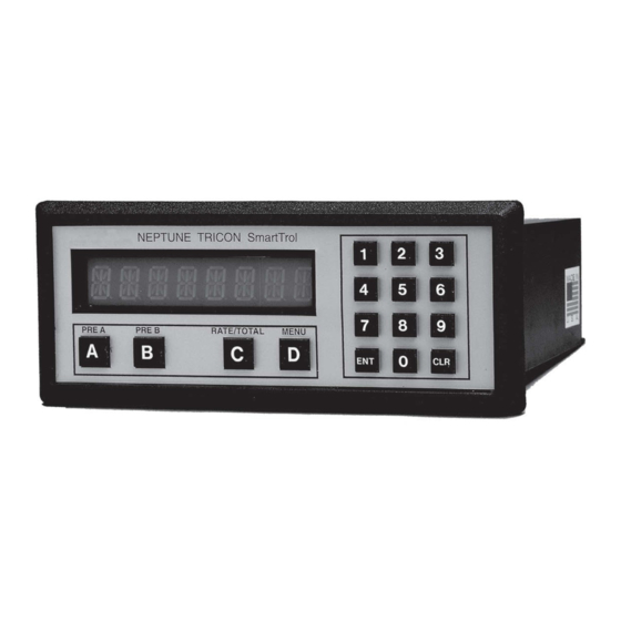
- Page 1 I N S T A L L A T I O N A N D M A I N T E N A N C E G U I D E TRICON SmartTrol ® ™...
- Page 2 This manual is an unpublished work and contains the trade secrets and confidential information of Neptune Technology Group Inc., which are not to be divulged to third parties and may not be reproduced or transmitted in whole or part, in any form or by any means, electronic or mechanical, for any purpose, without the express written permission of Neptune Technology Group Inc.
-
Page 3: Table Of Contents
I N T R O D U C T I O N ....................4 T Y P I C A L A P P L I C A T I O N . -
Page 4: N T R O D U C T I O N
CHAPTER INTRODUCTION The Neptune SmartTrol is a versatile microprocessor-based controller for use with TRICON/E ™ ® electronic registers. The main function of the unit is to display rate and totalization values and control relays for batching or alarming. TheSmartTrol allows two meter flows to be measured, separately scaled for both rate and total, then combined into one overall rate and one total. -
Page 5: Y P I C A L A P P L I C A T I O N
CHAPTER TYPICAL APPLICATION In the illustration below, the SmartTrol is used to power a single TRICON/E transmitter which, in turn, provides digital pulses to the SmartTrol. TheSmartTrol scales the pulse input to determine rate of flow and total quantity through the meter. The SmartTrol then uses the rate of flow or total values to operate two relays which may be used for single or two-stage batching, or under/over alarming. -
Page 6: P E R A T I N G T H E S M A R T T R O L
CHAPTER OPERATING THE SMARTTROL When power is initially applied, the SmartTrol is in the normal operating mode in which Total, Grand Total, and Rate are available for view. To view Total, Grand Total, or Rate, apply power. Press Display VER # . # (Displayed 1 second) ######## (Current value of Total) -
Page 7: E N E R A L D E S C R I P T I O N A N D P R I N C I P L E S O F O P E R A T I O N
CHAPTER GENERAL DESCRIPTION AND PRINCIPLES OF OPERATION 4.1 DISPLAY The SmartTrol shows one of three different variables on its 8-digit, alphanumeric displays: Total, Grand Total, or Rate. Total is typically the volume through the meter in units such as gallons, cubic feet, or cubic meters. Grand Total is similar to Total but continues to count when Total is reset (very useful for many batching operations). - Page 8 4.6 RATEMETER The ratemeter selection of the SmartTrol calculates Rate based on time between pulses from a maximum of two inputs. The resulting value of input pulses per second is then divided by the K Factor to display the Rate in units of volume per time. 4.7 COUNTER The counter section of the SmartTrol divides pulses from a maximum of two inputs by the Count K Factors to determine Total and Grand Total volumes through the meter in convenient units...
-
Page 9: P E C I F I C A T I O N S
CHAPTER SPECIFICATIONS HOUSING: High-impact plastic case with NEMA 4X front panel. DIMENSIONS: Reference 6.2, Page 12. DISPLAY: 8-character, 0.55” high, 15 segment, red-orange LED. INPUT POWER: 110 VAC +/- 15% or 12 to 27 VDC. CURRENT: 5.3 VA at rated AC voltage or maximum 280 mA DC. OUTPUT POWER: (On AC power units only) +12 VDC at 100 mA Separate isolated 12 VDC at 100 mA to allow +/- 12... - Page 10 CHAPTER MOUNTING AND INSTALLATION 6.1 PANEL MOUNTING The SmartTrol can be mounted in any panel with a thickness between .047” (1.2 mm) and .187” (4.7mm). It is shipped with two side mounting brackets and screws as well as a panel gasket. The gasket fits between the SmartTrol bezel and the front panel to form a NEMA 4 splash-proof assembly when properly panel-mounted.
- Page 11 CHAPTER CONNECTIONS TO THE SMARTTROL 7.1 POWER CONNECTION FOR ALTERNATING CURRENT (AC) (Refer to 7.5.1, Page 12) Be certain all power is removed from the wire before connecting the power wiring to the SmartTrol. Also be sure that the power is 120 VAC to prevent damage due to application of incorrect voltage. Connect the AC power across terminals 17 and 18 on the large terminal block.
- Page 12 7.5. 1 7.5.1 SmartTrol and Single TRICON/E Transmitter with Pulse Output and Remote Reset SmartTrol REMOTE RESET 1 Not Used 2 Scaled Output 3 Input B 4 Input A TRICON/E 5 Reset Input +12V 6 Not Used 7 Not Used PULSE OUTPUT 8 Not Used 9 Not Used...
- Page 13 7.5.3 SmartTrol and 4-20 mA TRICON/E and SmartChart 7.5.3 4-20 mA TRICON/E must be powered by 24 VDC. The SmartTrol is able to produce 24 VDC by “stacking” two independent 12 VDC power supplies. Configure the SmartTrol to provide +24 VDC by tying the +12 VDC (PIN 15).
- Page 14 7.5.4 7.5.4 SmartTrol with 4-20 mA Output Option and SmartChart and Single TRICON/E Transmitter with Pulse Output SmartTrol 1 Not Used Smart Chart 2 Scaled Output 4-20mA 3 Input B Source Return 4 Input A 5 Reset Input 6 Not Used 7 Not Used 8 Not Used 9 Not Used...
- Page 15 7.5.5 7.5.5 SmartTrol Powered by +24 VDC, Relays Controlling +24 VDC, and Single TRICON/E Transmitter with Pulse Output SmartTrol 1 Not Used 2 Scaled Output 3 Input B 4 Input A 5 Reset Input TRICON/E 6 Not Used 7 Not Used +24V 8 Not Used 9 Not Used...
- Page 16 7.5.6 7.5.6 SmartTrol and Single TRICON/S Transmitter with Pulse Output and Remote Reset Smart Trol Remote Reset 1 Not Used 2 Scaled Output 3 Input B 4 Input A 5 Reset Input 6 Not Used 7 Not Used TRICON/S 8 Not Used 9 Not Used CONTACTS PULSE OUTPUT...
- Page 17 7.5.7 7.5.7 SmartTrol with 4-20 mA Output Option and Remote Device and Battery-Powered TRU/MAG ™ Smart Trol W/4-20mA Output Option and Remote Device and Battery Powered TRU/MAG SmartTrol Remote Device 1 Not Used 4-20 mA 2 Scaled Output Source Return 3 Input B 4 Input A 5 Reset Input...
- Page 18 CHAPTER PROGRAMMING WORKSHEET CONFIGURED BY: ___________________ DATE: _____/ ______/ ______ MODEL NUMBER:___________________ APPLICATION: ____________ CALCULATION AREA________________ COUNTER K FACTOR A ________________________ K FACTOR B ________________________ RESET TO 0 _____________RESET TO PRESET_______ AUTOMATIC RESET_________MANUAL RESET_______ DECIMAL LOCATION ___# ___# ___# ___# ___# ___# ___# ___# RATEMETER K FACTOR A ______________________ K FACTOR B _______________________...
- Page 19 CHAPTER USING THE WORKSHEET The worksheet is an aid to help in setting the operating configuration of the SmartTrol. By filling out the worksheet first, all the data needed to program the unit is in front of you during programming. This makes programming the unit as simple as selecting items from a menu.
- Page 20 9.1.1.2 Changing Units of Volume The K Factor also may be modified so that the displayed values of Total or Grand Total are in units of measurement instead of gallons. To change the display from gallons to cubic feet, multiply the K Factor by 7.4805, which is the number of gallons per cubic foot. To change the display from gallons to cubic meters, multiply the K Factor by 264.172, the number of gallons per cubic meter.
- Page 21 9.1.4 Decimal Location In a previous example (9.1.1), the K Factor was divided by ten to display Total and Grand Total in tenths of gallons. The decimal point for the display must be set so that the value displayed using the decimal point will be the total in gallons, and the value displayed not using the decimal point will be the total in tenths of gallons.
- Page 22 9.2.1.2 Changing Units of Volume You may choose to display the Rate of flow in other units of volume such as cubic feet. Just multiply the gallons K Factor by the appropriate value. In the example determining the K Factor for the 4”...
- Page 23 9.3 LOCK OUT This feature prevents unauthorized access of the SmartTrol. The 4-digit numeric code entered is used to lock out access to the Menu during operation. When the lock out feature is active, no values can be cleared or changed by keyboard entry. Simply entering the code while Total, Grand Total, or Rate is displayed will change the lock condition.
- Page 24 The low and high limits may be customized to the application to provide higher resolution of the flow rate if the full range of flow rates is not used. If the flow rate was never less than 20 GPM and never more than 600 GPM, these values could be set to correspond to the 4 and 20 mA output levels respectively.
- Page 25 CHAPTER SETTING UP THE SMARTTROL The SmartTrol is configured by using the keyboard on the front panel of the unit. The Set Up Mode is entered by depressing the “D” key. In all cases, when “v” appears in the last position of the display, additional choices can be found by depressing the “D”...
- Page 26 10.2 SETTING UP THE RATEMETER PRESS DISPLAY MENU (Displays 1 second) DEV TYPv RTv CNTv K Fact A (Display 1 second) ######## (Current value blinks) 0 (Blinks) Key in new Rate K Factor A from worksheet K Fact B (Displays 1 second) ######## (Current value blinks) 0 (Blinks) Key in new Rate K Factor B from worksheet...
- Page 27 10.4 SETTING UP THE OUTCARD FOR RS-232 COMMUNICATIONS PRESS DISPLAY MENU (Displays 1 second) DEV TYPv LOCKOUTv OUTCARDv UNIT ## (Current Unit #) UNIT 00 Key in new Unit Number from worksheet PLv SERv Press D for Serial communications BAUDRATE (Displays 1 second) ####v (Current Baud Rate) Press D until Baud Rate value from worksheet is displayed PARITY (Displays 1 second)
- Page 28 10.6 SETTING UP THE RELAY OPERATION DISPLAY PRESS MENU (Displays 1 second) DEV TYP v LOCKOUTv OUTCARDv ALG OUTv RELAY v SCV MINV Press B for Seconds, press D for Minutes A #####v (Current Relay A comparison mode) Press D until Comparison mode from worksheet is displayed DUR A ## (Duration of Relay A if Comparison mode is Total or Grand Total) Key in new Output Duration from worksheet for Relay A, or if...
-
Page 29: R S - 2 3 2 C S E R I A L C O M M U N I C A T I O N O P E R A T I O N
CHAPTER RS-232C SERIAL COMMUNICATION OPERATIONS The RS-232C communications port provides the capability of obtaining information from the SmartTrol by a host computer. RS-232 is an EIA (ELECTRICAL INDUSTRY ASSOCIATION) specification for the electrical characteristics and signal assignments for a serial communication format. The SmartTrol expects the connection to the host computer to comply with the electrical characteristics for RS-232C. - Page 30 Once active, the SmartTrol operates in the full duplex mode and echos the commands from the host back to the host as they are received by the unit. Up to 80 command characters, including spaces, may be sent to the SmartTrol from the host in one transmission. The commands must be separated by spaces and the last character must be a “Carriage Return”.
- Page 31 Example: Unit Number 1 Host Command SmartTrol Response D1 (S) Device # 1: PA (S) 76546 (S) PA (S) PA 76546 PA (Keystrokes echo) KC (S) 1575 (S) KC (S) KC 1575 KC (Keystrokes echo) RC (Enter) RC (Keystrokes echo, request processed) 76546 (New Preset A value) 1575 (New rate K Factor for Input A) A sample communications program written in BASIC may be found in Appendix B, Page 38.
- Page 32 CHAPTER WARRANTY Neptune Technology Group warrants the SmartTrol against defects in materials and workmanship for a period of one (1) year from the date of shipment to the Buyer. The Warranty is limited to repair or replacement of the defective unit at the option of Neptune. This warranty is void if the product has been altered, misused, dismantled, or otherwise abused.
- Page 33 APPENDIX SPECIFICATIONS TRICON/E Performance Data T-10 Pulse Output Max Flow Max Continuous Pulses/ Flow for 20 mA Size Flow @ Max Flow (GPM) Flow (GPM) Gallon Output (GPM) (GPM) (CPS) ⁄ ” ⁄ 578.1 192.70 ⁄ ” ⁄ 322.6 161.30 1”...
- Page 34 HP Turbine Size Max Flow Max Continuous Min Flow Pulses/ Pulse Output Flow for 20 mA (GPM) Flow (GPM) (GPM) Gallon @ Max Cont. Output (GPM) Flow (CPS) ⁄ ” 6.095 16.25 2” 6.095 20.32 3” 11.20 84.00 4” 1,500 1,200 7.556 151.1...
- Page 35 Trident PROTECTUS (Turbine Side) ® Size Max Flow Max Continuous Min Flow Pulses/ Pulse Output @ Flow for 20 (GPM) Flow (GPM) (GPM) Gallon Max Cont. Flow mA Output (CPS) (GPM) 4” 1,250 1,000 1.590 26.50 1,000 6” 2,500 2,000 .464 15.47 2,000...
- Page 36 TRU/MAG HIGH FREQUENCY OUTPUT/K FACTOR Meter Qmax* Gallons Qmax* Liters Pulses per Gallon Pulses per Liter Size per Minute per Minute 3” 25.228 6.665 2,271 4” 16.362 4.323 1000 3,780 6” 6.307 1.666 2,400 9,462 8” 3.344 0.883 4,400 16,656 10”...
- Page 37 APPENDIX TRICON ® Performance Data Available switch closure rates GAL., IMP. GAL., OR CU. FT./CONTACT CU. METERS/CONTACT LITRES (*)/CONTACT METER 100 1000 100 1000 100 1000 ⁄ ”-1”T-10 ⁄ ”-2”T-10 ⁄ “-4”HPT ⁄ ”-6”HPT 6”-10”HPT 8”-10”HPT *Units of Litres per contact not available for 1 ⁄...
- Page 38 APPENDIX REGISTER TRACKING Making The Total Agree With The Register After programming the SmartTrol with the appropriate K Factor and operating parameters, you may set the SmartTrol so that the value of Total agrees with the current quantity indicated on the meter register. However, the meter must be static for the duration of the following procedure.
- Page 39 Keying in the current register reading. PRESS DISPLAY PRESET A (Displays 1 second) ######## (Current value blinks) PRESS DISPLAY Key in the current register reading SmartTrol returns to normal operating mode SmartTrol displays the current register reading, but still is in count down mode Setting the SmartTrol to increment Total keeping pace with the meter register.
- Page 40 Start the flow or reattach the register to the meter. As the register advances, so will Total as displayed on the SmartTrol. This procedure may need to be performed periodically due to rounding errors in the K Factor. To improve the matching of the percentage difference between Total and the register, the K Factor may be adjusted by the percentage difference between Total and the register reading.
- Page 41 Neptune Technology Group 1600 Alabama Highway 229 © 2019 Neptune Technology Group Inc. All Rights Reserved. The trademarks, logos and service marks displayed in this Tallassee, AL 36078 document herein are the property of Neptune Technology Group Inc., its affiliates or other third parties. Availability and technical specifications are subject to change without notice.
Need help?
Do you have a question about the TRICON SmartTrol and is the answer not in the manual?
Questions and answers