
Related Manuals for Digi AnywhereUSB Series


Summary of Contents for Digi AnywhereUSB Series
- Page 1 AnywhereUSB Remote I/O Concentrator User Manual Models: AnywhereUSB/2 AnywhereUSB/5 (G2) AnywhereUSB/5 AnywhereUSB/14 www.digi.com...
- Page 2 © 2010 Digi, Digi International, the Digi logo, USB Over IP, AnywhereUSB, Watchport, Edgeport, and Hubport are either trademarks or registered trademarks of Digi International, Inc. in the United States and/or other countries. Microsoft, Windows, Windows NT, Windows Server, Windows Vista are trademarks of Microsoft Corporation.
- Page 3 Product information is available on the Digi website, www.digi.com, including: Support Forums Knowledge Base Data sheets/product briefs Application/solution guides Regulatory Information For more information about Digi products, or for customer service and technical support, contact Digi International. To Contact Digi International by: Use: Mail Digi International...
- Page 4 This Page is Left Intentionally Blank AnywhereUSB User Manual (90001085_F1)
-
Page 5: Table Of Contents
Contents Introduction Product Overview AnywhereUSB/2 Interpreting the Status LEDs AnywhereUSB/5 (G2) Interpreting the Status LEDs AnywhereUSB/5 (First Generation) Interpreting the Status LEDs AnywhereUSB/14 Interpreting the Status LEDs AnywhereUSB/14 Features User Interfaces IP Address Assignment Security Features Configuration Management Getting Started In the Box Cabling Installing the Software... - Page 6 Adding IP addresses to the Discovery List Manager Using the Web User Interface Home Page Configuration Management Administration Multi-Host Connections AnywhereUSB Configuration PC Configuration Configuring via the Command Line Accessing the Command Line Hardware Specifications AnywhereUSB/2 Dimensions Environmental Power Requirements Network Interface Features Dimensions Environmental...
-
Page 7: Introduction
This Ethernet-attached solution provides either two or five USB ports to connect peripheral devices such as bar-code scanners and receipt printers, as well as Digi’s Watchport®/V2 USB Camera and Watchport Sensors. The AnywhereUSB/2, AnywhereUSB/14, and the second generation AnywhereUSB/5 (G2) units provide a built in Web Server and a command line (via Telnet) for additional configuration options. -
Page 8: Anywhereusb/2
AnywhereUSB/2 Front Panel Back Panel AnywhereUSB User Manual (90001085_F1) -
Page 9: Interpreting The Status Leds
Front Panel Information for the AnywhereUSB/2 System Status LED: Blinks green during normal operation. USB LEDs: Solid green when USB port is controlled by host PC; off when port is unowned. Reset Button: Used to either reboot the device or reset its configuration to factory defaults. -
Page 10: Anywhereusb/5 (G2)
AnywhereUSB/5 (G2) Front Panel Back Panel Note: The second generation AWUSB/5 (G2) uses an improved center- positive power-supply with a screw-down connector. The power-supplies are NOT interchangeable. Use only the power-supply that is provided with the unit. AnywhereUSB User Manual (90001085_F1) -
Page 11: Interpreting The Status Leds
Front Panel Information for the AnywhereUSB/5 (G2) System Status LED: Blinks green during normal operation. USB LEDs: Solid green when USB port is controlled by host PC; off when port is unowned. Reset Button: Used to either reboot the device or reset its configuration to factory defaults. -
Page 12: Anywhereusb/5 (First Generation)
AnywhereUSB/5 (First Generation) Front Panel Back Panel Warning: The first generation AWUSB/5 uses a center-negative power- supply which is different than second generation AWUSB/5 units The power-supplies are NOT interchangeable. Use only the power-supply that is provided with the unit. AnywhereUSB User Manual (90001085_F1) -
Page 13: Interpreting The Status Leds
Interpreting the Status LEDs The AnywhereUSB/5 has six LEDs on the front panel: one System Status LED and five hub LEDs. Each LED is capable of displaying three colors: red, green, or orange. System Status LED On initial power up the System Status LED is orange for two seconds while the system initializes and then blinks green. -
Page 14: Anywhereusb/14
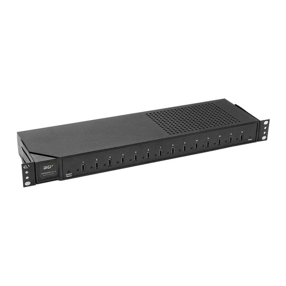
AnywhereUSB/14 Front Panel Information for the AnywhereUSB/14 System Status LED: Blinks green during normal operation. USB LEDs: Solid green when USB port is controlled by host PC; off when port is unowned. Reset Button: Used to either reboot the device or reset its configuration to factory defaults. -
Page 15: Anywhereusb/14
AnywhereUSB/14 Front Panel Back Panel Note: The AnywhereUSB/14 supports two power connectors, and two Ethernet connectors for redundancy. AnywhereUSB User Manual (90001085_F1) -
Page 16: Features
AnywhereUSB/5 (G2), and the AnywhereUSB/14 models. User Interfaces There are several user interfaces for configuring and monitoring the AnywhereUSB family, including: The Digi Device Setup Wizard, a wizard-based tool for assigning an IP address. Web-based interface for configuring, monitoring, and administering. -
Page 17: Security Features
Security Features Security-related features in AnywhereUSB include: Secure access and authentication - One password, one permission level. - Can selectively enable and disable network services such as ADDP, HTTP/HTTPS, Remote Login, Remote Shell, SNMP, and Telnet. - Can control access to inbound ports. - Secure sites for configuration: HTML pages for configuration have appropriate security. -
Page 18: Getting Started
This chapter explains what comes with each AnywhereUSB model and how to connect it to a Network. In the Box AnywhereUSB/2 AnywhereUSB/2 unit Digi AnywhereUSB Installation CD Power Supply AnywhereUSB/5 (G2) AnywhereUSB/5 unit Digi AnywhereUSB Installation CD ... -
Page 19: Cabling
Cabling To connect the AnywhereUSB to a Network: 1. Connect a standard Ethernet Network to the AnywhereUSB. 2. Connect the other end of the Ethernet cable to a 10-/100-BaseT switch or hub. 3. Connect one end of the power supply into the back of the AnywhereUSB and the other end into an AC outlet. -
Page 20: Installing The Software
For Windows XP, Vista, Server 2003, Server 2008, and Windows 7 1. Insert the Digi AnywhereUSB CD into the CD drive. 2. Select Install Drivers from the Digi splash screen. If the Digi splash screen does not launch, run the AWSplash.exe program from the CD. -
Page 21: Uninstalling The Drivers
A DOS Box will come up indicating the Install Process was successful. 4. Press the enter key to exit the DOS Box. The unit is now ready for configuration (see section 4). Uninstalling the Drivers To uninstall the AnywhereUSB drivers: 1. -
Page 22: Initial Anywhereusb Configuration
Initial AnywhereUSB Configuration This chapter explains how to configure the IP address in a new AnywhereUSB unit. Initial Configuration To begin the initial configuration: 1. Launch the AnywhereUSB Configuration Utility from the Start menu. A new AnywhereUSB will attempt to obtain an IP address from a DHCP Server. - Page 23 3. The Configure dialog is AnywhereUSB model specific. The following example is from an AnywhereUSB/2 with a static IP address configuration. 4. The following example is from an AnywhereUSB/14. The Group Number field selects the Group number to be used with the Multi- Host Connections feature described in Multi-Host Connections section.
-
Page 24: Configuring The Pc To Connect To An Anywhereusb
Configuring the PC to Connect to an AnywhereUSB This chapter explains how to configure the PC to establish a connection to the AnywhereUSB unit. Connecting to the AnywhereUSB In order to use the USB devices that are attached to the AnywhereUSB, the PC must establish a connection to the AnywhereUSB by adding the units IP address to the Connection List. - Page 25 2. Select an AnywhereUSB from the AnywhereUSB Configuration Utility Main Window and then either click the Connect button or right click on the selected AnywhereUSB and click Connect from the drop down box. The host computer then attempts to connect to the AnywhereUSB.
-
Page 26: Using The Configuration Utility Program
Using the Configuration Utility Program This chapter explains how to use the AnywhereUSB Configuration Utility. Configuration Utility Main Window The AnywhereUSB Configuration Utility displays AnywhereUSB devices grouped by their subnet addresses. The Utility automatically discovers AnywhereUSB devices on the local subnet; to discover devices on other subnets, add those subnet addresses to the Discovery List (see Section 7 Discovering AnywhereUSB Devices on Other Subnets AnywhereUSB User Manual (90001085_F1) -
Page 27: Menu Options
Icon Color Legend: Green—Available For Connection Gray, Bold Text—Connected to this computer. Gray—In use by other host PC. Red—Firmware is being updated. AnywhereUSB IP Address has not yet been configured, or is configured to connect to a non- existent Group in the case it is a multi-host connections enabled device. - Page 28 A Device ID consists of 3 parts: the name of the bus driver, the Product Identifier, and a unique serial number. For example, a Digi Edgeport USB to Serial converter that is plugged directly into the USB port of a PC would have a Device ID similar to: USB\VID_1608&PID_0215\A20299384...
- Page 29 Edit Menu: Connection List Displays the IP addresses of the AnywhereUSB to which the PC will try to connect. When an IP Address is added to this list, the host PC immediately tries to connect to the AnywhereUSB. If an IP Address is deleted from the Connection List, the AnywhereUSB unit will disconnect from the host PC and return to an “Available for Host Connection”...
- Page 30 Edit Menu: Discovery List Displays a list of subnet addresses of remote networks or IP Addresses of individual units where the configuration utility will search for AnywhereUSB units. AnywhereUSB User Manual (90001085_F1)
- Page 31 Command Menu: Configure This dialog configures the Device Name and IP address properties of the AnywhereUSB unit. Checking the Add to connection list box adds the IP address to the connection list. The Remote Hub field allows for a unique name to be given to the AnywhereUSB.
- Page 32 Command Menu: Connect This command allows the IP Address of the AnywhereUSB to be added to the connection list once the AnywhereUSB is selected in the Main Window. Command Menu: Event Log This command retrieves event information from AnywhereUSB. Use this to gather information for Technical Support.
- Page 33 Command Menu: Reboot This command causes the AnywhereUSB to reboot. Command Menu: Web UI This command opens the Web page of the selected unit. View Menu: Driver Information This command displays the version numbers of the AnywhereUSB drivers and firmware and allows for the uninstalling of the drivers. View Menu: Refresh (F5) This command updates the discovered AnywhereUSB listed in the Main Window.
-
Page 34: Discovering Anywhereusb Devices On Other Subnets
Discovering AnywhereUSB Devices on Other Subnets This chapter explains how to enable the Configuration Utility to discover AnywhereUSB units on additional IP subnets. Adding IP addresses to the Discovery List Manager To discover AnywhereUSB devices on other subnets, add their addresses to the Discovery List in the Discovery List Manager Dialog box. -
Page 35: Using The Web User Interface
Using the Web User Interface This chapter describes using the Web user interface’s Configuration, Management, and Administration sections and their corresponding sub- menus. With the exception of the title of the specific Configuration and Management screen, menus and sub-menus for both models remain the same. -
Page 36: Configuration
The Home Page The left side of the Home page has a list of choices that display pages for Configuration, Management, and Administration tasks, and to logout of the Web interface. Clicking Logout disconnects the configuration and management session with an AnywhereUSB. It does not close the browser window, but displays a logout window. - Page 37 Network Configuration Page View and Change IP Settings, as needed The Ethernet IP Settings page shows how the IP address for the AnywhereUSB is obtained, whether by DHCP or by static IP address, subnet mask, default gateway. Contact your network administrator for more information about these settings, and see the online help.
- Page 38 Several services have a setting for whether TCP keep-alives will be sent for the network services. TCP keep-alives can be configured in more detail on the Advanced Network Settings page. IP Network Failover Settings (AnywhereUSB/14 only) The IP Network Failover feature allows the AnywhereUSB/14 to recover from an Ethernet failure.
- Page 39 DNS Priority is a List of DNS servers in priority order used to resolve computer host names. Each type of server is tried, starting with the first in the list. For each server type, the primary server is tried first. If no response is received, then the secondary server is tried.
- Page 40 Configure Serial Port (AnywhereUSB/14 only) The Serial Ports page configures the serial port settings for the management port on the rear of the AnywhereUSB/14. Configure System Settings The System Configuration page configures System settings, including device description information, such as the device name, contact, and location, and whether SNMP is enabled or disabled and the SNMP traps that are enabled.
- Page 41 Configure SNMP Simple Network Management Protocol (SNMP) is a protocol that can be used to manage and monitor network devices. Digi devices can be configured to use SNMP features, or SNMP can be disabled entirely for security reasons. To configure SNMP settings, click the Simple Network Management Protocol link at the bottom of the System Configuration page.
- Page 42 Allow SNMP clients to set device settings through SNMP: This checkbox enables or disables the capability for users to issue SNMP “set” commands uses use of SNMP read-only for the AnywhereUSB. Enable Simple Network Management Protocol (SNMP) traps: Enables or disables the generation of SNMP traps.
- Page 43 Configure Remote Management Remote Management Settings The Remote Management configuration page sets up the connection to the Connectware Manager server so the AnywhereUSB knows how to connect to the server. The Connectware Manager server allows devices to be configured and managed from remote locations. In order to properly use this facility, the Connectware Manager server must first be installed on a server system.
- Page 44 Upon configuration of the Connectware Manager server and the Device ID, you must configure the following settings: Connection Settings These settings are used in connecting to the Connectware Manager server. You can choose how your AnywhereUSB connects to and communicates with the Connectware Manager server: through a client- initiated or a server-initiated connection.
- Page 45 Retry if the LKA update fails If enabled, when a LKA update fails, the Digi device server will wait the specified amount of time before retrying the LKA update. Advanced Settings These settings are used in advanced situations and the defaults are typically suitable for most environments.
- Page 46 AnywhereUSB User Manual (90001085_F1)
- Page 47 Network services that can be enabled or disabled include: ADDP: This service controls use of Advanced Digi Device Discovery Protocol. If it is disabled, you can no longer use the Digi Device Setup Wizard, or Digi Device Discovery utility to locate the device. ...
- Page 48 AnywhereUSB User Manual (90001085_F1)
-
Page 49: Management
Management The Management section displays additional information about the current connections to the AnywhereUSB. The example below lists the RealPort USB connection between the PC and the AnywhereUSB. AnywhereUSB User Manual (90001085_F1) -
Page 50: Administration
Administration Administration tasks need to be performed on the AnywhereUSB such as file management, changing the password used for logging onto the device, backing up and restoring device configurations, updating firmware and Boot/POST code, restoring the device configuration to factory defaults, and rebooting the device. - Page 51 AnywhereUSB User Manual (90001085_F1)
- Page 52 Backup/Restore Device Configurations Once the AnywhereUSB is configured, backing up the configuration settings is recommended in case problems occur later, firmware is upgraded, or hardware is added. If multiple devices need to be configured, the backup/restore feature can be used as a convenience, where the first device’s configuration settings are backed up to a file, and then the file is loaded onto the other devices.
- Page 53 Update Firmware and Boot/POST Code The firmware and/or Boot/Post code for the AnywhereUSB can be updated from a file on a PC. The AnywhereUSB automatically determines the type of image being uploaded. Before uploading the firmware or the Boot/POST code, it is very important to read the Release Notes supplied with the firmware to check if the Boot/POST code must be updated before updating the firmware.
- Page 54 Restoring a Device Configuration to Factory Defaults Restoring the AnywhereUSB to its factory default settings clears all current configuration settings. In addition, any files that were loaded into the device through the File Management page are also removed. There are two ways to reset the device configuration of an AnywhereUSB to the factory default settings: from the Web interface and using the front panel reset button.
- Page 55 Using the Front Panel Reset Button If the AnywhereUSB cannot be accessed from the Web interface, the configuration can be restored to factory defaults using the Reset button. 1. Power off the AnywhereUSB by unplugging the power. 2. Press the Reset button on the front of the unit. 3.
- Page 56 AnywhereUSB User Manual (90001085_F1)
- Page 57 Reboot the AnywhereUSB Changes to some device settings require saving the changes and rebooting the AnywhereUSB. To Reboot the Unit: 1. From the Web interface menu, select Administration > Reboot. 2. On the Reboot page, click the Reboot button. Wait approximately 1 minute for the reboot to complete.
-
Page 58: Multi-Host Connections
Multi-Host Connections This chapter describes the Multi-Host Connections feature which is available on the AnywhereUSB/14. AnywhereUSB Configuration The Multi-Host Connections feature allows multiple hosts to establish concurrent connections with the AnywhereUSB unit. Each host PC requests a group of USB ports, where the group assignments have been previously configured on the AnywhereUSB unit. - Page 59 2. The RealPort USB configuration page allows the user to select which physical USB ports on the AnywhereUSB unit are assigned to which USB Port Groups. By default, all the USB Ports are assigned to Group 1. So a host PC requesting either the Default Group, or Group 1, will take ownership of all of the physical USB ports on the AnywhereUSB unit.
- Page 60 3. In the AnywhereUSB/14 configuration example above, a host PC requesting Group 1 will only be granted access to physical USB Ports 1 through 4. A host PC requesting Group 2 will only be granted access to physical USB Ports 5 through 7. A host PC requesting Group 6 will only be given access to physical USB Port 11, and so on.
- Page 61 4. In the example above, the AnywhereUSB/14 unit has been configured to have 14 Groups, each providing access to a single physical USB port. The Default Group has been configured for “Unassigned” which would result in the AnywhereUSB unit rejecting any request from a host PC requesting access to the “Default Group”.
-
Page 62: Pc Configuration
PC Configuration Once the AnywhereUSB unit has been configured to support multiple Groups, the host PC needs to be configured to request one of the available Groups on the AnywhereUSB unit in order to establish a connection with the AnywhereUSB unit and take ownership of the USB Ports that are assigned to that Group. - Page 63 3. By default the host PC will request Group “0” (the Default Group). If this configuration isn’t appropriate for the AnywhereUSB unit, simply select the desired Group number, and then click “Update”. 4. After the list of AnywhereUSB devices is Refreshed (the F5 key performs a Refresh manually), right click on the AnywhereUSB unit and you will see a screen similar to the following AnywhereUSB User Manual (90001085_F1)
- Page 64 5. The PC will request Group 4 when establishing a connection with this particular AnywhereUSB unit. 6. Clicking the “Connect to Group 4” entry will initiate the connection process between the host PC and the selected AnywhereUSB/14 unit. 7. After the connection process completes, the AnywhereUSB Configuration Utility will update its Connection Status information and look similar to the following: AnywhereUSB User Manual (90001085_F1)
- Page 65 8. In the event the host PC requests a Group that is not configured on the AnywhereUSB unit, the host PC Connection Status will display something similar to the following indicating that the selected Group is not configured on the given AnywhereUSB unit (see below).
-
Page 66: Configuring Via The Command Line
Accessing the Command Line To configure devices using commands, first access the command prompt. Either launch the command-line interface from the last page of the Digi Device Setup Wizard or use the telnet command. Enter the telnet command from a command prompt on another networked device, such as a server, as follows: # >... - Page 67 To Configure: Use This Command: system-identifying information set system host name set host network options set network network services set service ethernet set ethernet user and passwords set user newpass AnywhereUSB User Manual (90001085_F1)
-
Page 68: Hardware Specifications
Hardware Specifications This section proved the physical dimensions, environmental, and power requirements of the AnywhereUSB. AnywhereUSB/2 Dimensions Length: 2.38 in (6.04 cm) Width: 3.9 in (10 cm) Height: 1.0 in (2.54 cm) Weight: 5 oz. (142 g) Environmental Operating temperature: 32 F to 131 F (0 C to 55... -
Page 69: Network Interface Features
Hardware Interface Features Memory: 64MB RAM Network Interface Features Standards: IEEE 802.3, 802.3i (10Base-T), 802.3u (100Base-TX), 802.3x (full duplex and flow control), HP Auto-MDIX (auto-detection of straight- through or crossover cabling) Physical layer: 10/100 Mbps in half- or full-duplex mode, with auto- negotiation of speed and duplex. -
Page 70: Dimensions
AnywhereUSB/5 (G2) Dimensions Length: 4.35 in (11.05 cm) Width: 7.20 in (18.29 cm) Height: 1.03 in (2.61 cm) Weight: 10.00 oz. (283.5g) Environmental Operating temperature: 32 F to 131 F (0 C to 55 Relative humidity: 0% to 95% (non-condensing) Power Requirements The AnywhereUSB uses a 120/230VAC 50/60Hz power adapter that supplies 5VDC to the unit. -
Page 71: Network Interface Features
Network Interface Features Standards: IEEE 802.3, 802.3i (10Base-T), 802.3u (100Base-TX), 802.3x (full duplex and flow control), HP Auto-MDIX (auto-detection of straight- through or crossover cabling) Physical layer: 10/100 Mbps in half- or full-duplex mode, with auto- negotiation of speed and duplex. Ethernet connector: RJ-45 AnywhereUSB User Manual (90001085_F1) -
Page 72: Dimensions
AnywhereUSB/5 (First Generation) Dimensions Length: 4.35 in (11.05 cm) Width: 7.20 in (18.29 cm) Height: 1.03 in (2.61 cm) Weight: 10.00 oz. (283.5g) Environmental Operating temperature: 32 F to 131 F (0 C to 55 Relative humidity: 0% to 95% (non-condensing) Power Requirements Power to this product many be supplied by a UL Listed Direct Plug-In Power Unit marked “Class 2”... - Page 73 AnywhereUSB/14 Dimensions Length: 4.97 in (12.62 cm) Width: 17.00 in (43.18 cm) Height: 1.74 in (4.42 cm) Weight: 40.00 oz. (1134g) Environmental Operating temperature: 32 F to 131 F (0 C to 55 Relative humidity: 0% to 95% (non-condensing) Power Requirements The AnywhereUSB/14 uses single or dual 120/230VAC 50/60Hz power input(s) through the rear IEC 60320 inlet(s).
- Page 74 Network Interface Features Standards: IEEE 802.3, 802.3i (10Base-T), 802.3u (100Base-TX), 802.3x (full duplex and flow control), HP Auto-MDIX (auto-detection of straight- through or crossover cabling) Physical layer: 10/100 Mbps in half- or full-duplex mode, with auto- negotiation of speed and duplex AnywhereUSB User Manual (90001085_F1)
-
Page 75: Regulatory And Safety Information
Regulatory and Safety Information All relevant domestic and international regulatory and safety information, including Declaration of Conformity (DoC) notices, may be found at www.digi.com/certifications. When prompted, enter the part number printed on the product label. Warning for the AnywhereUSB/14 only: HAZARDOUS VOLTAGE INSIDE. -
Page 76: Troubleshooting
Troubleshooting If you are having a problem installing the AnywhereUSB drivers inside a virtual machine due to a Code 39 error: Does the virtual machine have the file "USBD.SYS" in the "...\system32\drivers" folder? If not, the following workaround is required: 1. - Page 77 4. Reboot the virtual machine. 5. After Windows loads, the AnywhereUSB Host Controller(s) and AnywhereUSB/RealPortUSB Root Hub(s) component(s) in Windows Device Manager should successfully install automatically. AnywhereUSB User Manual (90001085_F1)
-
Page 78: Anywhereusb Permitted Device List
Appendix A AnywhereUSB Permitted Device List An option has been added to the AnywhereUSB product that will limit access to a set of select devices. This option allows an administrator to build a list of supported devices by adding specific Vendor ID/Product ID or Class values into the registry. - Page 79 The USB Device’s Vid/Pid values can be found using the provided AnywhereUSB View utility. The fields are called idVendor and idProduct. In the following example, the highlighted USB Flash Drive has the following properties: idVendor: 0x13FE idProduct: 0x1D00 AnywhereUSB User Manual (90001085_F1)
-
Page 80: Understanding Hubs
Appendix B Understanding Hubs Hubs, critical components in the plug-and-play architecture, are wiring concentrators that enable the attachment of multiple devices, thus converting a single attachment point into multiple attachment points. USB architecture allows a cascaded multiple hub configuration with certain power limitations (explained later in this section). -
Page 81: Configuring For Firewall Support
Appendix C Configuring for Firewall Support To access an AnywhereUSB that is behind a firewall: Your firewall must have a well known static IP address (for example 10.52.48.37). The AnywhereUSB must have an IP address on the private subnet (for example 192.168.1.10).
Need help?
Do you have a question about the AnywhereUSB Series and is the answer not in the manual?
Questions and answers