Table of Contents
Advertisement
Quick Links
Advertisement
Table of Contents

Related Manuals for Lex Computech 2I385D

Summary of Contents for Lex Computech 2I385D
- Page 1 2I385D Intel Bay Trail-I E3815/ E3825(Single Core / Dual Core )CPU, On Board DDR3L, 3 x Intel I211AT LAN / mini USB / VGA All-In-One Intel Bay Trail-I E3815/ E3825, 1.46/1.33GHz VGA, PCIe mini card Multi-LAN Board , mini USB NO.
-
Page 2: Table Of Contents
1-4 PACKING LIST ......................CHAPTER 2 HARDWARE INSTALLATION ..............2-1 UNPACKING PRECAUTION ..................2-2 UNPACKING CHECKUP ....................2-3 DIMENSION-2I385D ....................2-4 LAYOUT-2I385D-CONNECTOR MAP ................2-4-1 LAYOUT-2I385D-FUNCTION MAP ................2-5 DIAGRAM-2I385D ....................... 2-6 LIST OF JUMPERS ...................... 2-7 JUMPER SETTING DESCRIPTION ................ - Page 3 4-6-4 THERMAL CONFIGURATION .................. 4-6-5 SATA CONFIGURATION ..................4-6-6 ACPI TABLE/FEATURES CONTROL ................ 4-7 SECURITY ........................4-8 POWER ........................4-9 BOOT ........................... 4-9-1 LEGACY ........................4-9-2 BOOT TYPE ORDER ....................4-10 EXIT ........................... 4-11 DEVICE MANAAGER ....................4-11-1 SIO FINTEK81801U ....................4-11-2 HARDWARE MONITOR ..................
- Page 4 Copyright This manual is copyrighted and all rights are reserved. It does not allow any non authorization in copied, photocopied, translated or reproduced to any electronic or machine readable form in whole or in part without prior written consent from the manufacturer.
-
Page 5: Warning
Warning ! Battery Batteries on board are consumables. The life time of them are not guaranteed. 2. Fless solution with HDD The specifi cation & limitation of HDD should be considered carefully when the fanless solution is implemented. We will not give further notifi cation in case of changes of product information and manual. -
Page 6: Hardware Notice Guide
Hardware Notice Guide 1. Before linking power supply with the motherboard, please attach DC-in adapter to the motherboard fi rst. Then plug the adapter power to AC outlet. Always shut down the computer normally before you move the system unit or remove the power supply from the motherboard. - Page 7 Photo 1 Insert Unplug...
-
Page 8: Chapter 1 General Information
Chapter-1 General Information The 2I385D SBC with built-in 3 x Intel Giga LAN ports as an economic and flexible hardware platform for industrial communication solution. A reliable and efficient communication network which connects all the components of the factory to work together effectively plays an important role of success industrial automation. -
Page 9: Major Feature
1-1 Major Feature 1. Intel Bay-Trail-I E3825 1.33GHz SOC (Daul core) 2. Intel Bay-Trail-I Integrated Graphics chipset, E3825 533 MHz render clock frequency 3. On board DDR3L SDRAM 2GB Memory, data transfer rate of 1066MT/s 4. Support 3 x 10/100/1000 Mbps Intel LAN ports 5. -
Page 10: Specification
1-2 Specifi cation 1. SOC: Intel Bay-Trail-I E3825 1.33GHz Daul core) 2. Memory: DDR3L SDRAM 2GB Memory, data transfer rate of 1066MT/s 3. Graphics: Intel Bay=Trail-I Integrated Graphics chipset, E3825 533 MHz MHz render clock frequency 4. I/O Chip : F81801U I/O chipset for 2 ports RS485 5. -
Page 11: Directions For Installing The Mini Card
1-3 Directions for installing the Mini Card 1. Unscrew the screw on the board 2. Plug in the Mini Card in a 45 angle 3. Gently push down the Mini Card and screw the screw back. -
Page 12: Packing List
1-4 Packing List Material Code Description Detail Specifi cation Quantit 7G1901-1615001-0 MB-2I385D-I22-001 LF, 2I385D-I22,Rev.:001 6G8006-2349-0100 LEX Product Driver DVD LF, Intel Baytrail Driver,Windows 7/8.1 32/64 6G6003-7329-0100 Power Cable LF,L=9cm,2.0 1*2/DC JK 6G5212-0301-0600 30W Power Adapter,12V/2.5A LF,L Type,EA1024H1(06),EDAC *The packing list above is for the users who purchase single motherboard. The users who purchase the board with chassis may refer to the packing list in the Assembly Guide. -
Page 13: Chapter 2 Hardware Installation
1. Ground yourself by a grounded wrist strap at all times when you handle the 2I385D. Well secure the ALLIGATOR clip of the strap to the end of the shielded wire lead from a grounded object. -
Page 14: Unpacking Checkup
2-2 Unpacking checkup First of all, please follow all necessary steps of section 2-1 to protect 2I385D from electricity discharge. With reference to section 1-4 please check the delivery package again with following steps: 1. Unpack the 2I385D board and keep all packing material, manual and driver disc etc, do not dispose ! 2. -
Page 15: Dimension-2I385D
2-3 Dimension-2I385D... -
Page 16: Layout-2I385D-Connector Map
2-4 Layout-2I385D- Connector MAP MPCE1 LED1 BAT1 CPI1 JSB1... -
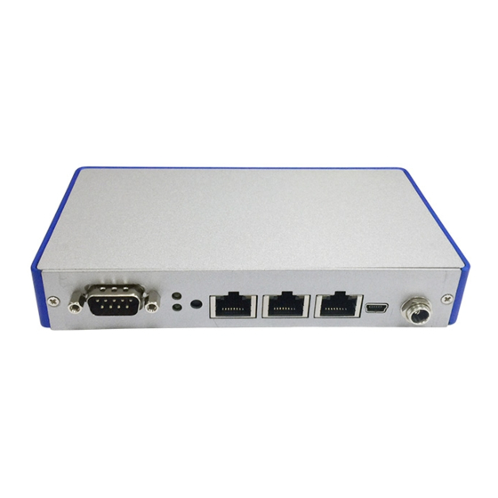
Page 17: Layout-2I385D-Function Map
2-4-1 Layout-2I385D-Function MAP LAN3 RJ45 Reset buttom or RS485 port2 USB2.0 water UP.POWER LAN2 RJ45 mSATA Only DOWN:HDD mini USB LAN1 RJ45 or RS485 port1 2 x RS485 Clear CMOS Jumper DC-IN 12V to 24V... -
Page 18: Diagram-2I385D
2-5 Diagram- 2I385D MPCE1 LED1 BAT1 JSB1 CPI1 BACK Panel- 2I385D Reset buttom mini USB LAN3 LAN2 LAN1... -
Page 19: List Of Jumpers
2-6 List of Jumpers JSB1: CMOS DATA clear 2-7 Jumper Setting Description A jumper is ON as a closed circuit with a plastic cap covering two pins. A jumper is OFF as an open circuit without the plastic cap. Some jumpers have three pins, labeled 1, 2, and 3. -
Page 20: Jsb1: Coms Data Clear
2-8 JSB1: CMOS Data Clear A battery must be used to retain the motherboard confi guration in CMOS RAM. Close Pin1 and pin 2 of JSB1 to store the CMOS data. To clear the CMOS,follow the procedures below: 1. Turn off the system and unplug teh AC power 2. -
Page 21: Chapter 3 Connection
Chapter-3 Connection This chapter provides all necessary information of the peripheral's connections, switches and indicators. Always power off the board before you install the peripherals. 3-1 List of Connectors BAT1: Li 3V battery holder CPI1: +12V power input 2 pin (2.0mm) wafer Red. CG1: VGA wafer 2x5 pin (2.0mm) wafer CC1: 2Ports RS485 wafer 2x3 pin (2.0mm) wafer CU2: USB2.0 wafer 1x4 pin (1.25mm) wafer... -
Page 22: Coms Battery Connector
3-2 CMOS Battery connector BAT1: Battery use Li 3V / 40mAh (CR1220) PIN NO. Description +VRTC 3.3V BAT1 3-3 DC Power input CPI1: DC Power input (2pin 2.0mm Wafer) (Red) PIN NO. Description DC-IN(12V to 24V) Note: Very important check Dc-in Voltage pin1 CPO1... -
Page 23: Vga Connector
3-4 VGA connector CG1: VGA 2x5pin 2.0mm wafer connector PIN NO. Description PIN NO. Description BULE DDC CLOCK GREEN V-SYNC H-SYNC DDC DATA pin1 3-5 COM connector CC1: 2 Ports RS485 wafer 2x3 pin (2.0mm) wafer PIN NO. Description PIN NO. Description RS485 P1 DATA- RS485 P2 DATA-... -
Page 24: Lan Connector
3-7 LAN Connector CL1/2/3: RJ45 LAN Connector PIN NO. Description PIN NO. Description MDI0+ MDI2- MDI0- MDI1- MDI1+ MDI3+ MID2+ MDI3- RJ45 LAN LED Behavior Speed Right (Orange) Left ( Green) 10/100 Link 10/100 Active Blink 1000 Link 1000 Active Blink CL2/3 RS485 over RJ45 Connector PIN NO. -
Page 25: Pci Express Mini Card
3-8 PCI Express Mini card MPCE1 only Support mSATA interface PIN NO. Description PIN NO. Description +3.3V +1.5V Reset mSATA-RX+ +3.3V mSATA-RX- +1.5V SMB-CLK pin52 mSATA-TX- SMB-DATA mSATA-TX+ +3.3V +3.3V pin1 MPCE1 +1.5V +3.3V... -
Page 26: Connextor Wafer Of Compatible Brand And Part Number List
3-9 Connector wafer of Compatible Brand and part number list Location CKTS PITCH Brand Name Mating connector Cable housing 2x3 6Pin 2.00mm HIROSE DF13-06DS-1.25C DF13-06DP-1.25V 2x5 10Pin 2.00mm HIROSE DF13-06DS-1.25C DF13-06DP-1.25V CPI1 1x2 2pin 2.00mm B2B-PH-KL PHR-2 1x4 4Pin 1.25mm MOLEX 53047-0410 51021-0400... -
Page 27: Introduction Of Bios
Chapter-4 Introduction of BIOS The BIOS is a program located in the Flash Memory on the motherboard. This program is a bridge between motherboard and operating system. When you start the computer, the BIOS program gains control. The BIOS fi rst operates an auto-diagnostic test called POST (Power on Self Test) for all the necessary hardware, it detects the entire hardware devices and confi... -
Page 28: Bios Menu Screen & Function Keys
4-2 BIOS Menu Screen & Function Keys In the above BIOS Setup main menu of, you can see several options. We will explain these options step by step in the following pages of this chapter, but let us fi rst see a short description of the function keys you may use here: Press ←→... -
Page 29: Getting Help
4-3 Getting Help Status Page Setup Menu/ Option Page Setup Menu Press F1 to pop up a help window that describes the appropriate keys to use and the possible selections for the highlighted item. To exit the Help Window, press <Esc>. -
Page 30: Menu Bars
4-4 Menu Bars There are six menu bars on top of BIOS screen: Main To change system basic confi guration Advanced To change system advanced confi guration Security Password settings Power PME & Power button settings Boot Exit Save setting, loading and exit options. User can press the right or left arrow key on the keyboard to switch from menu bar. -
Page 31: Advanced
4-6 Advanced Boot Confi guration Please refer section 4-6-1 PCI Express Confi guration Please refer section 4-6-2 Video Confi guration Thermal Confi guration Please refer section 4-6-4 SATA Confi guration Please refer section 4-6-5 ACPI Table/Features Control Please refer section 4-6-6... -
Page 32: Boot Configuration
4-6-1 Boot Confi guration Numlock Select Power-on state for Numlock, default is <ON> 4-6-2 PCI Express Confi guration PCIe 1/2/3 confi guration settings... -
Page 33: Pci Express Root Port 1/2/3/4
4-6-2-1 ► PCI Express Root Port 1/2/3 Control the PCI Express Root Port. The optional settings are: Enabled(default), Disabled. Select PCI Express port speed. The optional settings are: Gen1(default), Gen2 Select PCIE TXE ROM support The optional settings are: Disabled(default), Enabled 4-6-3 Video Confi... -
Page 34: Thermal Configuration
Aperture Size The optional settings are: 128MB, 256MB(default), 512MB. IGD - DVMT Pre-Allocated Use this item to select DVMT 5.0 pre-allocated (fi xed) graphics memory size used by the internal graphics device. The optional settings are: 64(default)/96/128/160/192/224/256/288/320/352/384/416/448/480/512MB IGD - DVMT Total Gfx Mem Use this item to select DVMT 5.0 total graphics memory size used by the internal graphics device The optional settings are:128M, 256M(default), MAX 4-6-4 Thermal Confi... -
Page 35: Sata Configuration
Thermal Confi guration Parameters This Value controls the temperature of the ACPI Critical Trip Point, the point in which the OS will shutdown the system. Critical Trip point is the shutdown temperature, the default value is 110˚ The CPU frequency will auto reduce when cpu temperature arrived to passive Trip point. The default of the passive trip point is 105˚... -
Page 36: Acpi Table/Features Control
SATA Controller Use this item to Enable or Disable SATA Device. The optional settings are: Enabled(default) or Disabled Chipset SATA Mode Determine how SATA controller(s) operate. The optional settings are: IDE Mode(default), AHCI Mode. SATA Speed Indicates the maximum speed the SATA controller can support. The optional settings: Gen1, Gen2(default). -
Page 37: Security
4-7 Security Supervisor Password To set up an Supervisor password 1. Select Supervisor Password. The screen then pops up an Create New Password dialog. 2. Enter your desired password that is no less than 3 characters and no more than 10 characters. 3. -
Page 38: Boot
Wake on LAN Determines the action taken when the system power is off and the PCI power management Enable wake up event occurs. The optional settings: S3, S5, S3/S5, Disabled (default) Wake on USB Determines the action taken when the system power is off and use USB KB/MS to Enable wake up event occurs. -
Page 39: Legacy
4-9-1 Legacy Normal Boot Menu Select Normal Boot option priority or Advance Boot option priority. The optional settings: Normal(default), Advance 4-9-2 Boot Type Order Boot Type Order Setting the boot type priority. The default settings is 1.USB drive 2.Hard Disk Drive 3.CD/DVD ROM drive 4.Others... -
Page 40: Exit
4-10 EXIT Exit Saving Changes This item allows user to reset the system after saving the changes. Save Change Without Exit This item allows user to saving the changes but doesn’t restart. Exit Discard Changes This item allows user restart the system but no saving the changes Load Optimal Default Use this item to restore the optimal default for all the setup options. -
Page 41: Device Manaager
4-11 Device Manager Please press the key F10 when boot up to go into the Device Manager menu Serial Port 1/2 Confi guration Please refer section 4-11-1... -
Page 42: Sio Fintek81801U
4-11-1 SIO FINTEK81801U Serial Port 1/2 Use this item to enable or disable serial port (COM1 or COM2). The optional settings are: Enabled(default), Disabled. Serial Port 1 Base IO Address / Interrupt Use this item to select an optimal setting for super IO device. The optional settings are: IO=3F8h;... -
Page 43: Hardware Monitor
4-11-2 Hardware Monitor Press [Enter] to view PC health status. This section shows the status of your CPU, Fan, and overall system. This is only available when there is Hardware Monitor function onboard. -
Page 44: Chapter 5 Driver Installation
Chapter-5 DRIVER INSTALLATION There is a system installation DVD in the package. This DVD does not only include all the drivers you need but also some other free application programs and utility programs. In addition, this DVD also includes an auto detect software telling you which hardware is installed and which driver is needed so that your system can function properly. - Page 45 AUTOMATIC DRIVER INSTALLATION menu...
- Page 46 1. INF Install Intel Baytrail chipset driver 2. VGA Install onboard VGA driver 3. LAN To the LAN driver Readme fi le 4. TXE Patch Install Intel TXE patch (FOR Win 7 only) 4.1. TXE Install Intel TXE driver Each selection is illustrated below:...
-
Page 47: Inf Install Intel Baytrail Chipset Driver (Example For Win8 64Bit)
5-1 INF Install Intel Baytrail Chipset Driver (example for WIN8 64bit) 1. At the "AUTOMATIC DRIVER INSTALLATION 2. At the "Intel® Chipset Device Software" menu" screen, click "INF". screen, click "Next". 3. At the "License Agreement" 4. At the "Readme File Information" screen, screen,click "Yes"... - Page 48 5. Click "Next" 6. Click "Finish" & restart computer. NOTE: SYSTEM INSTALL will auto detect fi le path For Windows 7 64/32-bit, X:\driver\INTEL\BAY\INF\WIN7\infi nst_autol.exe For Windows 8 / 8.1 32/64-bit X:\driver\INTEL\BAY\INF\WIN_8_64\infi nst_autol.exe...
-
Page 49: Vga Install Intel Baytrail Vga Driver (Example For Win8 64Bit)
5-2 VGA Install Intel Baytrail VGA Driver (example for WIN8 64bit) 1. At the"AUTOMATIC DRIVER INSTALLATION 2. At the "Welcome to the Setup Program menu"screen, click "VGA". screen, Click "Next". 3. At the "License Agreement" screen, 4. At the "Readme File Information" screen, Click "Yes"... - Page 50 6. Click "Finish" to restart computer 5. At the "Setup Progress" screen, Click "Next". NOTE: SYSTEM INSTALL will auto detect fi le path For Windows 7 32-bit, X:\driver\INTEL\BAY\VGA\WIN_7_32\Setup.exe For Windows 7 64-bit X:\driver\INTEL\BAY\VGA\WIN_7_64\Setup.exe For Windows 8 / Windows 8.1 32-bit X:\ \driver\INTEL\BAY\VGA\WIN_8_32\Setup.exe For Windows 8 / Windows 8.1 64-bit X:\driver\INTEL\BAY\VGA\WIN_8_64\Setup.exe...
-
Page 51: Txe Install Intel Txe Driver
5-3 TXE Install Intel TXE driver 5-3-1 TXE Install for WIN8/WIN8.1 1. At the "AUTOMATIC DRIVER INSTALLATION 2. At the "Setup" screen, Click "Next". menu", click "TXE" 3. At the "License Agreement" screen, 4. Click "Next". Click "Yes". - Page 52 5. Click "Finish" & restart computer NOTE: SYSTEM INSTALL will auto detect fi le path For Windows 8 32 / 64-bit, X:\driver\INTEL\BAY\TXE\WIN_8\SetupTXE.exe For Windows 8.1 32 / 64-bit, X:\driver\INTEL\BAY\TXE\WIN_8.1\SetupTXE.exe...
-
Page 53: Txe Install For Win7
5-3-2 TXE Install for WIN7 Please install PXE Patch fi rst. 1. At the "AUTOMATIC DRIVER INSTALLATION 2. At the "Windows Update" screen, menu", click "TXE Patch " Click "Yes". 3. Click "Finish" & restart computer 4. At the "AUTOMATIC DRIVER INSTALLATION menu", click "TXE "... - Page 54 5. At the "TXE Setup" screen, Click "Next". 6. At the "License Agreement" screen, Click "Yes". 8. Click "Finish" & restart computer 7. Click "Next". NOTE: SYSTEM INSTALL will auto detect fi le path For Windows 7 32 / 64-bit, TXE Patch X:\driver\INTEL\BAY\TXE\WIN_7\kmdf-1.11-Win-6.1-x86.msu X:\driver\INTEL\BAY\TXE\WIN_7\kmdf-1.11-Win-6.1-x64.msu...
-
Page 55: How To Update Insyde Bios
STEP 3. Copy the latest BIOS for your LEX motherboard from our website to your bootable disc. STEP 4. (Here take 2I385D as an example, please enter your motherboard’s name) Insert your bootable disc into X: (X could be C:, A: or others. -
Page 56: Appendix A:power Consumption Test
Appendix A: Power Consumption Test Condition Item Spec Atom E3815 1.46 Ghz / E3825 1.33 Ghz Memory DDR3L 1066 2GB Operating System Windows 7 / SP1 Test Program 3D Mark 06 mSATA 64GB Test Result for reference only ! Start up Operation Shut down In Put... -
Page 57: Appendix B:resolution List
Appendix B: Resolution list 640 x 480 x ( 256 / 16bit / 32bit ) 800 x 600 x ( 256 / 16bit / 32bit ) 1024 x 768 x ( 256 / 16bit / 32bit ) 1152 x 864 x ( 256 / 16bit / 32bit ) 1280 x 600 x ( 256 / 16bit / 32bit ) 1280 x 720 x ( 256 / 16bit / 32bit ) 1280 x 768 x ( 256 / 16bit / 32bit )
Need help?
Do you have a question about the 2I385D and is the answer not in the manual?
Questions and answers