Advertisement
Quick Links
INSTALLATION AND MAINTENANCE INSTRUCTIONS
These instructions must be read and understood completely before attempting installation.
The equipment covered in this manual is to be installed by trained and experienced
service and installation technicians. Improper installation, modification, service, or use
can cause electrical shock, fire, explosion, or other conditions which may cause personal
injury, death, or property damage. Use appropriate safety gear including safety glasses
and gloves when installing this equipment.
Risk of electrical shock. Disconnect all remote power
supplies before installing or servicing any portion of the
system. Failure to disconnect power supplies can result
in property damage, personal injury, or death.
Installation and servicing of air conditioning equipment
can be hazardous due to internal refrigerant pressure
and live electrical components. Only trained and
qualified service personnel should install or service
this equipment. Installation and service performed by
unqualified persons can result in property damage,
personal injury, or death.
Sharp metal edges can cause injury. When installing
the unit, use care to avoid sharp edges.
506257-01
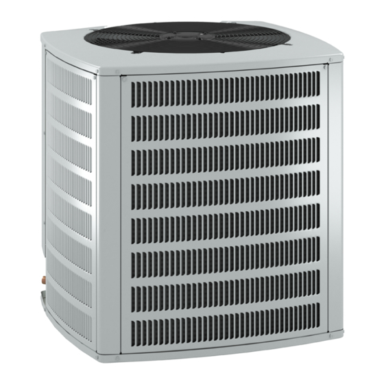
4SHP18LT SERIES
Split System Heat Pump
WARNING
WARNING
WARNING
WARNING
INSTALLATION ...................................... 2
CONNECTION DIAGRAM ....................... 4
START-UP ............................................. 13
OPERATION .......................................... 18
MAINTENANCE .................................... 23
WARRANTY .......................................... 28
A Lennox International Inc. Company
Issue 1330
TABLE OF CONTENTS
Manufactured By
Allied Air Enterprises, Inc.
215 Metropolitan Drive
West Columbia, SC 29170
*P506257-01*
(p) 506257-01
Page 1 of 29
Advertisement

Subscribe to Our Youtube Channel
Related Manuals for Lennox Allied Air 4SHP18LT Series


Summary of Contents for Lennox Allied Air 4SHP18LT Series
-
Page 1: Table Of Contents
Installation and service performed by unqualified persons can result in property damage, personal injury, or death. Manufactured By Allied Air Enterprises, Inc. A Lennox International Inc. Company 215 Metropolitan Drive West Columbia, SC 29170 WARNING *P506257-01* Sharp metal edges can cause injury. When installing the unit, use care to avoid sharp edges. -
Page 2: Installation
INSTALLATION Inspection of Shipment Upon receipt of equipment, carefully inspect it for possible shipping damage. If damage is found, it should be noted on General the carrier’s freight bill. Take special care to examine the unit Read this entire instruction manual, as well as the inside the carton if the carton is damaged. - Page 3 • Install the unit high enough above the ground or roof to If unit coil cannot be mounted away from prevailing winter allow adequate drainage of defrost water and prevent winds, a wind barrier should be constructed (See Figure 3). ice buildup.
-
Page 4: Connection Diagram
Refrigerant Piping If the 4SHP18LT unit is being installed with a new indoor coil and line set, the refrigerant connections should be made as outlined in this section. If an existing line set and/or indoor coil will be used to complete the system, refer to this section as well as the section that follows entitled - Flushing Existing Line Set and Indoor Coil. - Page 5 Placement Brazing Connection Procedure Be aware that some localities are adopting sound ordinances 1. Cut ends of refrigerant lines square (free from nicks or based on how noisy the unit is at the neighbor’s home, not dents). Debur the ends. The pipe must remain round; do at the original installation.
- Page 6 6. Braze the line set to the service valve. Quench the joints with water or a wet cloth to prevent heat damage to CAUTION the valve core and opening port. The tube end must stay bottomed in the fitting during final assembly to ensure When flushing existing line set and/or indoor coil, be sure to proper seating, sealing, and rigidity.
- Page 7 Refrigerant Line Sets: Transition from Vertical to Horizontal Automotive Anchored Muffler-Type Heavy Nylon Hanger Wire Tie Strap Liquid Strap Liquid Line to Vapor Line to Vapor Line Wall Wall Line Stud Stud Liquid Line Liquid Line – Vapor Line Wrapped –...
- Page 8 Flushing Existing Line Set and Indoor Coil existing system. Refer to the gauges after shutdown to confirm that the entire system is completely void of This procedure should not be performed on systems refrigerant. Disconnect the liquid and suction lines from which contain contaminants, such as compressor burn the existing outdoor unit.
- Page 9 4. Remove the existing R-22 refrigerant flow control orifice An R410A system will not operate properly with an R-22 or thermal expansion valve before continuing with flushing metering device. procedures. R-22 flow control devices are not approved for use with R-410A refrigerant and may prevent proper Install the refrigerant metering device as shown in Figure flushing.
- Page 10 Suction Line (Ball Type) Service Valve 3. Connect the external equalizer line to the equalizer port on the suction line and tighten to 8 ft.lbs. Suction line (ball type) service valves function the same way as the other valves; the difference is in the 4.
- Page 11 3. Open the high pressure side of the manifold to allow R410A into the line set and indoor unit. Weigh in a trace amount of R410A. (A trace amount is a maximum of 2 oz. of refrigerant or 3 lbs. pressure.) Close the valve on the R410A cylinder and the valve on the high pressure side of the manifold gauge set.
- Page 12 4. Open both manifold valves and start vacuum pump. 5. Evacuate the line set and indoor unit to a minimum of 500 microns or lower. During the early stages of evacuation, it is desirable to close the manifold gauge valve at least once to determine if there is a rapid rise in pressure.
-
Page 13: Start-Up
START-UP Units are factory charged with the amount of R410A refrigerant indicated on the unit rating plate. This charge is based on a matching indoor coil and outdoor coil with CAUTION 15’ line set. For varying lengths of line set, refer to Table 4 for refrigerant charge adjustment. - Page 14 Figure 13 Measure the liquid line temperature and the outdoor ambient 1. Recover the refrigerant from the unit. temperature as outlined below: 1. Connect the manifold gauge set to the service valve ports 2. Conduct a leak check, then evacuate as previously as follows (See Figure 13 above): outlined.
- Page 15 R-410A Temperature/Pressure Chart T e m p . P re s s u re T e m p . P re s s u re T e m p . P re s s u re P s ig P s ig P s ig F F...
- Page 16 6. Compare the approach value with those shown in Table 9. If the values do not agree with those provided in Table 8, add refrigerant to lower the approach temperature or recover refrigerant from the system to increase the approach temperature. Check Charge Using Normal Operating Pressures Use Table 8 to perform maintenance checks.
- Page 17 Normal Operating Pressures L - Liquid S- Suction Values provided above are typical pressures. Indoor unit matchup, indoor air quality equipment, and indoor load will case pressures to vary. Table 8 506257-01 Issue 1330 Page 17 of 29...
-
Page 18: Operation
OPERATION Emergency heat is usually used during an outdoor shutdown, but it should also be used following a power outage if power has been off for over an hour and the outdoor temperature Outdoor unit and indoor blower cycle on demand from is below 50°F. - Page 19 Defrost Control Timing Pins locked out until power to the board is interrupted, then re- Each timing pin selection provides a different accumulated established, or until the jumper is applied to the TEST pins compressor run time period during one thermostat run cycle. for 0.5 seconds.
- Page 20 System Diagnostic Module TRIP LED (Red) indicates there is a demand signal from 4SHP18LT units contain a diagnostic module for the thermostat but no current to the compressor is detected troubleshooting heat pump system failures. By monitoring by the module. The TRIP LED typically indicates the and analyzing data from the compressor and thermostat compressor protector is open or may indicate missing demand, the module can accurately detect the cause of...
- Page 21 24VAC Power Wiring Every time the module powers up, the last ALERT LED flash code that occurred prior to shutdown is displayed for The diagnostic module requires a constant nominal 24VAC 60 seconds. The module will continue to display the power supply.
- Page 22 Thermostat Demand Wiring Miswired Module Codes The diagnostic module requires a thermostat demand signal Depending on the system configuration, some ALERT flash to operate properly. The thermostat demand signal input, codes may not be active. The presence of safety switches labeled Y on the module, should always be connected affects how the system alerts are displayed by the module.
-
Page 23: Maintenance
MAINTENANCE WARNING Before performing maintenance operations on system, turn the electric power to unit OFF at disconnect switch(es). Unit may have multiple power supplies. Electrical shock could cause personal injury or death. Before the start of each heating and cooling season, the following service checks should be performed by a qualified service technician. - Page 24 HOMEOWNER INFORMATION to substances which are corrosive or which block airflow across the coil (such as pet urine, cottonwood seeds, etc...). In order to ensure peak performance, your system must be properly maintained. Clogged filters and blocked airflow Heat Pump Operation prevent your unit from operating at its most efficient level.
- Page 25 Fan Switch Preservice Check In AUTO or INT (intermittent) mode, the blower operates If your system fails to operate, check the following before only when the thermostat calls for heating or cooling. This calling for service: mode is generally preferred when humidity control is a priority.
- Page 26 Start-Up and Performance Checklist Job Name _____________________________ Job No. ____________ Date ___________ Job Location ___________________________ City _______________ State ___________ Installer _______________________________ City _______________ State ___________ Unit Model No. _________________________ Serial No._____________________________ Service Technician _______________________ Nameplate Voltage _____________________ Rated Load Ampacity _________ Compressor Amperage ________ Outdoor Fan __________ Maximum Fuse or Circuit Breaker ________________________...
- Page 27 Wire Diagram LT BLUE OUTDOOR BLUE YELLOW BLACK DUAL CAPACITOR THERMOSTAT GREEN BLACK O-OUT LO-PS YELLOW COMMON BLUE Y1 OUT BLACK HI-PS DEFROST CONTROL COMPRESSOR A132 YELLOW CRANKCASE HEATER 208-230/60/1 GROUND GROUND THERMOSTAT CMC1 Y1 Y2 REVERSING VALVE O-OUT DEFROST THERMOSTAT LO-PS BLACK...
-
Page 28: Warranty
ALLIED AIR ENTERPRISES EQUIPMENT LIMITED WARRANTY APPLIES IN U.S.A. AND CANADA ONLY FAILURE TO MAINTAIN YOUR EQUIPMENT WILL VOID THIS WARRANTY COVERED EQUIPMENT The following Allied Air Enterprises heating and cooling equipment is covered by the Limited Warranty, Condensing Units: 2SCU13, 4SCU13, 4SCU14, 4SCU16, 4SCU18, 2AC13, 2AC14, 4AC13, 4AC14 Heat Pumps: 2SHP13, 4SHP13, 2SHP14, 4SHP14, 4SHP16, 4SHP18, 2HP13, 2HP14, 4HP13, 4HP14, 4HP16, 4HP18 Gas Furnaces: G1N80, G1D80, G2D80, G1D91, G1D93, G2D93, G2D95, FPBB, CG80, CG90, CG92, CG93, CG95, A96, A95, A952V, A93, A80, 95G2, 95G2V, 95G1, 92G1, 80G2, 80G1 Oil Furnaces: LBR80, LBF80, LHF80, LUF80, LHR80, L83, RLUF, RLBF, RLBR, RLBU, RLHF, RLHR, ODHA, OLFA, OLRA, OUFA... - Page 29 5-YEAR LIMITED EXTENDED PARTS WARRANTY Allied Air Enterprises Inc. (“Allied Air”) provides its air conditioning and heating products with a Standard Limited Parts Warranty for five (5) years. This additional 5-Year Limited Extended Parts Warranty is in addition to and is intended to supplement Allied Air’s Standard Limited Parts Warranty. As such, Allied Air provides for a total of 10-years of limited warranty coverage (Standard Limited Parts Warranty plus additional 5-Year Limited Extended Parts Warranty).
Need help?
Do you have a question about the Allied Air 4SHP18LT Series and is the answer not in the manual?
Questions and answers