Table of Contents
Advertisement
Quick Links
PRODUCT LITERATURE
1995 Lennox Industries Inc.
Dallas, Texas
Î Î Î
HP25 HEAT PUMP UNIT
HP25 heat pump units are designed for expansion valve
systems only. They are not designed for RFC systems.
Refer to Lennox engineering handbook for expansion
valve kits which must be ordered separately.
SHIPPING AND PACKING LIST
1- Assembled HP25 heat pump unit
Check unit for shipping damage. Consult last carrier
immediately if damage is found.
GENERAL INFORMATION
These instructions are intended as a general guide and
do not supersede national or local codes in any way.
Authorities having jurisdiction should be consulted be
fore installation.
IMPORTANT
The Clean Air Act of 1990 bans the intentional
venting of refrigerant (CFC's and HCFC's) as of July
1, 1992. Approved methods of recovery, recycling
or reclaiming must be followed. Fines and/or in
carceration may be levied for non-compliance.
INSTALLATION
INSTRUCTIONS
HP25 SERIES UNITS
HEAT PUMP UNITS
503,302M
6/95
Supersedes 503,247M
TABLE OF CONTENTS
. . . . . . . . . . . . . . . . . . . . . . . . . . . . . . . . . . . . . .
. . . . . . . . . . . . . . . . . . . . . . . . . . . . . . . . . . . . . . .
. . . . . . . . . . . . . . . . . . . . . . . . . . . . . . . . . . . .
. . . . . . . . . . . . . . . . . . . . . . . . . . . . . . . . . . . . .
. . . . . . . . . . . . . . . . . . . . . . . . . . . . . . . . . . . . . . . .
. . . . . . . . . . . . . . . . . . . . . . . . . . . . . . . . . . . . . . .
RETAIN THESE INSTRUCTIONS
FOR FUTURE REFERENCE
Product contains fiberglass wool.
Disturbing the insulation in this product during
installation, maintenance, or repair will expose
you to fiberglass wool. Breathing this may cause
lung cancer. (Fiberglass wool is known to the
State of California to cause cancer.)
Fiberglass wool may also cause respiratory, skin,
and eye irritation.
To reduce exposure to this substance or for further
information, consult material safety data sheets
available from address shown below, or contact
your supervisor.
Lennox Industries Inc.
P.O. Box 799900
Dallas, TX 75379-9900
Page 1
. . . . . . . . . . . . . . . . . . . . . . . . . . . .
. . . . . . . . . . . . . . . . . . . . . .
. . . . . . . . . . . . . . . . . . . . . . . . . .
. . . . . . . . . . . . . . . . . . . . . . . . . .
. . . . . . . . . . . . . . . . . . . . . .
. . . . . . . . . . . . . . . . . . . . . . . . . . . . . . . .
. . . . . . . . . . . . . . . . . . . . . . . . . . . . . . . . . .
. . . . . . . . . . . . . . . . . . . . . . . . . . . . . .
. . . . . . . . . . . . . . . . . . . . . . . . . . . . . . . .
. . . . . . . . . . . . . . . . . . . . . . . . . . . . . . . . . .
. . . . . . . . . . . . . . . . . . . . . . . . . . . . .
WARNING
Litho U.S.A.
1
1
1
2
3
3
4
5
5
6
6
7
7
9
9
11
12
Advertisement
Table of Contents

Related Manuals for Lennox HP25 Series


Summary of Contents for Lennox HP25 Series
-
Page 1: Table Of Contents
HP25 heat pump units are designed for expansion valve RETAIN THESE INSTRUCTIONS systems only. They are not designed for RFC systems. FOR FUTURE REFERENCE Refer to Lennox engineering handbook for expansion valve kits which must be ordered separately. SHIPPING AND PACKING LIST WARNING 1- Assembled HP25 heat pump unit Check unit for shipping damage. -
Page 2: Hp25 Unit Dimensions
HP25 UNIT DIMENSIONS-INCHES (MM) INLET HP25 HEAT PUMP UNIT INLET COMPRESSOR INLET COIL DRAIN OUTLETS TOP VIEW (Around perimeter of base) ELECTRICAL INLETS DISCHARGE VAPOR LINE INLET (HP25 211 460) LIQUID LINE INLET (HP25 510 650) LIQUID LINE INLET (HP25 211 460) VAPOR LINE INLET (HP25 510 650) -
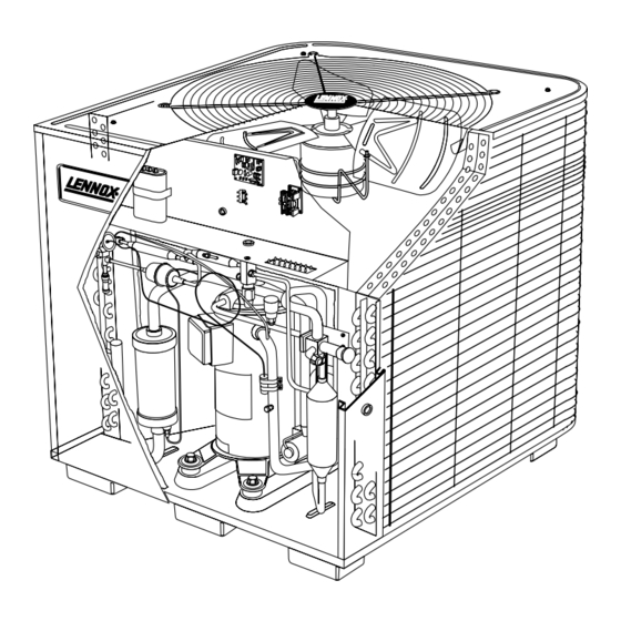
Page 3: Hp25 Parts Arrangement
L10 or L15 line sets, and refrigerant control de 2- Mount unit high enough above ground or roof to al vices as designated by Lennox. Refer to the Lennox En gineering Handbook for approved systems. low adequate drainage of defrost water and prevent ice build-up. -
Page 4: Electrical
Slab Mounting (See figure 3) ELECTRICAL When installing unit at grade level, top of slab should Wiring must conform to the National Electric Code be high enough above the grade so that water from (NEC) and local codes. Application diagram is included higher ground will not collect around unit. -
Page 5: Plumbing
(sweat connections). Use (HCFC-22) refrigerant indicated on the unit rating Lennox L10 (flare) or L15 (sweat) series line sets as plate. This charge is based on a matching indoor coil shown in table 1 or field-fabricated refrigerant lines. -
Page 6: Leak Testing
1- Connect manifold gauge set to the service valve ports LEAK TESTING as follows: low pressure gauge to vapor line service After the line set has been connected to the indoor and valve; high pressure gauge to liquid line service valve. outdoor units, the line set connections and indoor unit 2- Connect the vacuum pump (with vacuum gauge) must be checked for leaks. -
Page 7: Start-Up
2- Inspect all factory and field-installed wiring for total amount shown on the unit nameplate and in table 3. Refer to the Lennox Unit Information Service manual loose connections. for proper procedure. - Page 8 HP25 COOLING CYCLE (Showing Gauge Manifold Connections) EXPANSION CHARGE COMPENSATOR SUCTION HIGH VALVE PRESSURE REVERSING VALVE FILTER DRIER STRAINER WITH INTERNAL CHECK VALVE DISCHARGE MUFFLER VAPOR LINE VALVE INDOOR UNIT LIQUID LINE VALVE CHECK COMPRESSOR VALVE THERMOMETER WELL NOTE-Use gauge ports on vapor line valve and liquid valve for evacuating refrigerant lines EXPANSION and indoor coil.
-
Page 9: System Operation
Table 6 gives compressor oil charge for HP25 units. Re The HP25 is equipped with an auto-reset high pressure fer to Lennox Cooling Service Handbook for correct pro switch (single-pole, single-throw) which is located on cedure for checking and adding compressor oil. - Page 10 The TEST mode may be started at anytime. If the jumper out pressure switch on the third open pressure switch is in the TEST position at power-up or for longer than occurrence. See table 7. The unit will remain locked out five minutes, the control will ignore the TEST selection until power is broken then remade to the control.
-
Page 11: Maintenance
2- Adjust blower speed for cooling. The pressure drop WARNING over the coil should be checked to determine the cor rect blower air volume. Refer to the Lennox Engi Electric shock hazard. Can cause injury or death. Before attempting to per... -
Page 12: Hp25 Check Points
HP25 CHECK POINTS START-UP AND PERFORMANCE CHECK LIST Job Name Job No. Date City Job Location State Installer City State Unit Model No. Serial No. Service Technician Nameplate Voltage Amps: Minimum Circuit Ampacity Supply Outdoor Fan Maximum Overcurrent Protection Size Compressor Electrical Connections Tight? Indoor Filter Clean?
Need help?
Do you have a question about the HP25 Series and is the answer not in the manual?
Questions and answers