
Subscribe to Our Youtube Channel
Related Manuals for shelolab SVAC1E


Summary of Contents for shelolab SVAC1E
- Page 1 ECONOMY VACUUM OVENS 110 – 120 Volts 220 – 240 Volts Installation - Operation Manual SVAC1E SVAC2E / SVAC1E-2 SVAC2E-2...
- Page 2 Pictured on cover left to right: SVAC1E, SVAC2E The SVAC1E and SVAC2E ovens require a 110 – 120-volt NEMA 5-15R power outlet. The SVAC1E-2 and SVAC2E-2 require a CEE7 220 – 240-volt power outlet compatible with CEE7/7 cords to plug in to.
- Page 3 Economy Vacuum Ovens 110 – 120 Voltage — SVAC1E SVAC2E 220 – 240 Voltage — SVAC1E-2 SVAC2E-2 Part Number (Manual): 4861658 Revision: November 22, 2021 ISO C ERTIFIED ANUFACTURER SHEL LAB is a brand of Sheldon Manufacturing, INC, an ISO 9001 certified manufacturer.
-
Page 4: Table Of Contents
TABLE OF CONTENTS INTRODUCTION ................................ 5 Read this Manual ..................................5 Safety Considerations and Requirements ........................5 Contacting Assistance ................................6 Manufacturing Warranty ..............................6 Engineering Improvements..............................6 Vacuum Supply Required ..............................7 Gaskets ..................................... 8 RECEIVING YOUR UNIT ............................9 Inspect the Shipment ................................ -
Page 5: Introduction
INTRODUCTION Thank you for purchasing a SHEL LAB oven. We know you have many choices in today’s competitive marketplace when it comes to constant temperature equipment. We appreciate you choosing ours. We stand behind our products and will be here if you need us. EAD THIS ANUAL Failure to follow the guidelines and instructions in this user manual may create a protection... -
Page 6: Contacting Assistance
INTRODUCTION ONTACTING SSISTANCE Phone hours for Customer Support are 6 am – 4:30 pm Pacific Coast Time (west coast of the United States, UTC -8), Monday – Friday. Please have the following information ready when calling or emailing Customer Support: the model number, serial number, and part number (see page 13). support@sheldonmfg.com 1-800-322-4897 extension 4 (503) 640-3000 extension 4... -
Page 7: Vacuum Supply Required
INTRODUCTION ACUUM UPPLY EQUIRED The oven does not come with a vacuum pump. A pump must be separately purchased for the oven. Consult a vacuum pump specialist to determine the pump type best suited to your baking application. The correct selection of a vacuum pump is critical for evacuating the chamber to the level required for your vacuum baking applications in a timely manner. -
Page 8: Gaskets
INTRODUCTION ASKETS Gaskets are non-warranty, high-wear consumable items subject to compression forces, heat, and outgassed byproducts. Heavy usage rates may necessitate frequent replacements. The manufacturer strongly recommends keeping a spare gasket on hand during operation. Each oven comes with a replaceable silicone gasket installed on the chamber liner. This gasket seals against the chamber door to maintain the vacuum integrity of the chamber. -
Page 9: Receiving Your Unit
RECEIVING YOUR UNIT NSPECT THE HIPMENT When a unit leaves the factory, safe delivery becomes the responsibility of the carrier. • Damage sustained during transit is not covered by the manufacturing defect warranty. • Save the shipping carton until you are certain that the unit and its accessories function •... -
Page 10: Orientation Images
RECEIVING YOUR UNIT RIENTATION MAGES SVAC1Es Chamber Door Oven Chamber Chamber Gasket Seal Door Latch Control Panel Shelves 10 | P a g e... - Page 11 RECEIVING YOUR UNIT SVAC2Es Chamber Door Chamber Gasket Seal Oven Chamber Door Latch Shelves Control Panel 11 | P a g e...
- Page 12 RECEIVING YOUR UNIT Figure 1: Unit Back Chamber Vent Port ¼ inch (6.35 mm) Vacuum Port 3/8 inch (9.52 mm) Power Cord Inlet Fuse Holders (One holder only in 110-120 Voltage units) 12 | P a g e...
-
Page 13: Record The Data Plate Information
RECEIVING YOUR UNIT ECORD THE LATE NFORMATION The data plate contains the unit model number, part number, and serial number. Tech Support will need this information during any support call. Record it below for future reference. The data plate is located on the back of the oven above the power inlet. •... - Page 14 RECEIVING YOUR UNIT 14 | P a g e...
-
Page 15: Installation
INSTALLATION NSTALLATION ROCEDURE HECKLIST Carry out the procedures and steps listed below to install the oven in a new workspace location and prepare it for use. All procedures are found in the Installation section of this manual. Pre-Installation Verify a vacuum supply source suitable for your application is available and can be connected to the oven. -
Page 16: Required Ambient Conditions
INSTALLATION EQUIRED MBIENT ONDITIONS When selecting a location to install the unit, consider all environmental conditions that can adversely impact its temperature performance. These include: Proximity to other ovens, autoclaves, and any device that produces significant radiant heat • Heating and cooling vents or other sources of fast-moving air currents •... -
Page 17: Power Source Requirements
Power Cord: The unit must be positioned so that all end-users can quickly unplug the oven in the event of an emergency. SVAC1E and SVAC2E units come provided with a 125-volt, 15 amp, 8ft 2 in (2.5m) NEMA 5- •... -
Page 18: Lifting And Handling
INSTALLATION IFTING AND ANDLING The oven is heavy. Use appropriate lifting devices that are sufficiently rated for these loads. Follow these guidelines when lifting the oven: Lift the oven only from its bottom surface. • Doors, handles, and knobs are not adequate for lifting or stabilization. •... -
Page 19: Install The Oven
INSTALLATION NSTALL THE Place the unit in a workspace location that meets the criteria discussed in the previous entries of the Installation section. EIONIZED AND ISTILLED ATER Do not use deionized water to clean the unit. The use of deionized water may corrode metal surfaces and voids the warranty. -
Page 20: Shelving Installation
INSTALLATION HELVING NSTALLATION SVAC economy ovens are provided with 2 identical stacking shelves. Install both shelves. Never place samples or product on the oven chamber floor. The floor runs hotter than the shelf temperatures. All heating specifications for the oven are for shelving temperatures. Carefully slide one shelf into position on the chamber floor. -
Page 21: Connect To The Vacuum Supply
INSTALLATION ONNECT TO THE ACUUM UPPLY Chamber Vent Port (Backfill Inlet) ¼ in (6.35 mm) Vacuum Port 3/8 in (9.52 mm) Vacuum and Vent inlet ports Vacuum Line Connected to the Vacuum Port Use clamps to secure tubing to the Vacuum Port and Chamber Vent Port (backfill inlet). The Vacuum Port –... - Page 22 INSTALLATION 22 | P a g e...
-
Page 23: Graphic Symbols
GRAPHIC SYMBOLS The unit is provided with multiple graphic symbols on its exterior. The symbols identify hazards and the functions of the adjustable components, as well as important notes in the user manual. Symbol Definition Consult the user manual Consulter le manuel d'utilisation Temperature display Indique l'affichage de la température Potential shock hazard... - Page 24 GRAPHIC SYMBOLS 24 | P a g e...
-
Page 25: Control Overview
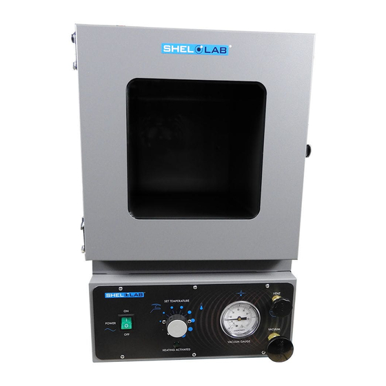
CONTROL OVERVIEW Figure 2: Control Panel Power Switch Power is supplied to the unit when the switch is in the ( I ) ON position. Temperature Control Dial This graduated dial sets the oven operating temperature. The dial is marked with 10 major increments and 9 minor increments, which can be used as index points for setting and returning to temperature levels. - Page 26 CONTROL OVERVIEW Vacuum Gauge This gauge indicates the level of vacuum within the chamber. The dial displays a vacuum pressure range of 0 – 76 cmHg and 0 – 30 inHg, with 30 inHg. Zero indicates ambient atmospheric pressure and 30 indicates a perfect vacuum level. Vacuum Control Valve This valve adjusts the level of vacuum draw applied to the oven chamber through the 3/8in Vacuum Port on the back of the oven.
-
Page 27: Operation
OPERATION Safe operation of the oven is dependent on the actions and behavior of the oven operators. Operating personnel must read and understand the Operating Precautions in this section prior to operating the oven. The operators must follow these instructions to prevent injuries and to safeguard their health, environment, and the materials being treated in the oven, as well as to prevent damage to the oven. -
Page 28: Theory Of Operation
OPERATION HEORY OF PERATION These units are intended for use in closed-cycle, under-vacuum applications. Vacuum The oven chamber is evacuated by a vacuum pump or building system. The vacuum supply is connected to the Vacuum Port on the back of the oven. The current level of relative vacuum is displayed on the Vacuum Gauge on the main control panel. - Page 29 OPERATION Heating in a Vacuum In conventional ovens, a powered element transfers heat into the chamber air. The heated air then circulates by natural convection or blower fan action, and surrounds the product on the shelves, gradually bringing it to temperature. In a vacuum oven, there is no atmosphere to transport heat evenly from the elements to the product.
-
Page 30: Put The Oven Into Operation
OPERATION Note: You may place a dial thermometer in the oven chamber prior to turning on the oven if you will be setting the oven to a specific temperature. See page 34 for thermometer requirements. UT THE VEN INTO PERATION Verify all the required procedures in the Installation section have been carried out. - Page 31 OPERATION Continued from the previous page Set the Oven Chamber to an Approximate Temperature See the Select Approximate Oven Temperature procedure on page 33. Optional: Temperature Matching Set the oven to a specific temperature using a reference thermometer. See the Temperature Matching procedure on •...
-
Page 32: Evacuating The Oven Chamber
OPERATION VACUATING THE HAMBER Put the oven chamber under vacuum for at least 10 minutes when first putting the oven into operation in a new location to verify the integrity of the vacuum supply system. Evacuate the Oven Chamber Verify the Vent Valve control is in the closed position (all the way clockwise) VENT Verify the Vacuum Valve control is in the closed position (all the way clockwise). -
Page 33: Select Approximate Oven Temperature
OPERATION ELECT PPROXIMATE EMPERATURE Set the Approximate Oven Temperature Low Temp Turn the Temperature controller knob to the approximate position for your application, using the graduated dial as a reference guide. Med Temp High Temp Approximate Approximate Controller Position Controller Position Temperature Temperature 30 –... -
Page 34: Temperature Matching
OPERATION EMPERATURE ATCHING This procedure sets the oven to a specific temperature using a reference thermometer. Required Thermometer Type: A dial style bimetallic thermometer. Do not use an alcohol or mercury thermometer. These can rupture under vacuum. Place the thermometer on the top shelf of the oven where the face will be visible through the glass door. - Page 35 OPERATION Temperature Matching (continued) Wait 45 minutes for the chamber temperature to stabilize The chamber must be evacuated to accurately match the • dial setting to a specific temperature. Check the thermometer temperature If the thermometer temperature matches your • application temperature or is close enough, the temperature matching procedure is now complete.
-
Page 36: Maximum Obtainable Vacuum
OPERATION AXIMUM BTAINABLE ACUUM The maximum vacuum obtainable is set by the altitude of the oven workspace or laboratory environment. The atmosphere is less dense at higher altitudes than at sea level. While a vacuum pump will evacuate the same percentage of atmosphere from the oven chamber, less overall pressure is expelled because of the reduced density. -
Page 37: User Maintenance
USER MAINTENANCE Warning: Disconnect the unit from its power supply prior to maintenance or cleaning of this unit. Avertissement: Avant d'effectuer toute maintenance ou entretien de cet appareil, débrancher le cordon secteur de la source d'alimentation. LEANING AND ISINFECTING If a hazardous material or substance has spilled in the unit, immediately initiate your site Hazardous Material Spill Containment protocol. -
Page 38: Maintaining Atmospheric Integrity
MAINTENANCE Oven Exterior Cleaning Guidelines 1. Disconnect the unit from its power supply. 2. The manufacturer recommends cleaning the unit with a mild soap and water solution. Do not use abrasive cleaners, these will damage metal surfaces. • Cleaning agents must be compatible with steel and powder coat paint surfaces. •... -
Page 39: Unit Specifications
UNIT SPECIFICATIONS SVAC1E and SVAC2E units are 110-120 VAC. SVAC1E-2 and SVAC2E-2 units are 220-240 VAC. Please refer to the oven data plate for individual electrical specifications. Technical data specified applies to units with standard equipment at an ambient temperature of 25°C and at nominal voltage. -
Page 40: Capacity
UNIT SPECIFICATIONS APACITY Model Cubic Feet Liters 0.56 15.9 SVAC1E 1.67 47.2 SVAC2E 0.56 15.9 SVAC1E-2 1.67 47.2 SVAC2E-2 HELF APACITY BY EIGHT Model Per Shelf Max Total Load Max No. Shelves 35.0 lb / 15.8 kg* 70.0 lb / 31.7 kg** SVAC1E 35.0 lb / 15.8 kg*... -
Page 41: Temperature
UNIT SPECIFICATIONS EMPERATURE Range, Stability, and Uniformity Model Range Stability Uniformity SVAC1E Ambient +15° to 210°C ±0.5°C @ 100°C ±9.0 @ 110 SVAC2E Ambient +15° to 210°C ±0.5°C @ 100°C ±9.0 @ 110 SVAC1E-2 Ambient +15° to 210°C ±0.5°C @ 100°C ±9.0 @ 110... - Page 42 UNIT SPECIFICATIONS 42 | P a g e...
-
Page 43: Parts List
PARTS LIST See next page for gaskets. Description Parts Number Description Parts Number Shelf, SVAC2Es Shelf, SVAC1Es 5680566 5680567 Ordering Parts and Consumables If you have the Part Number for an item, you may order it directly from Sheldon Manufacturing by calling 1-800-322-4897 extension 3. -
Page 44: Replacement Gaskets
PARTS LIST EPLACEMENT ASKETS Available Gasket Types Part Number Silicon, black or red, (comes with oven), rated to 230°C Applications: General and high temperature SVAC1Es: 3450706 Resistant to: Moderate or oxidizing chemicals, ozone, and concentrated sodium hydroxide SVAC2Es: 3450707 Attacked by: Many solvents, oils, concentrated acids, and diluted sodium hydroxide Buna rated to 105°C Applications: Solvent... - Page 45 PARTS LIST 45 | P a g e...
- Page 46 P.O. Box 627 Cornelius, OR 97113 support@sheldonmfg.com sheldonmanufacturing.com 1-800-322-4897 (503) 640-3000 FAX: 503 640-1366...
Need help?
Do you have a question about the SVAC1E and is the answer not in the manual?
Questions and answers