
Related Manuals for shelolab SMO14-2


Summary of Contents for shelolab SMO14-2
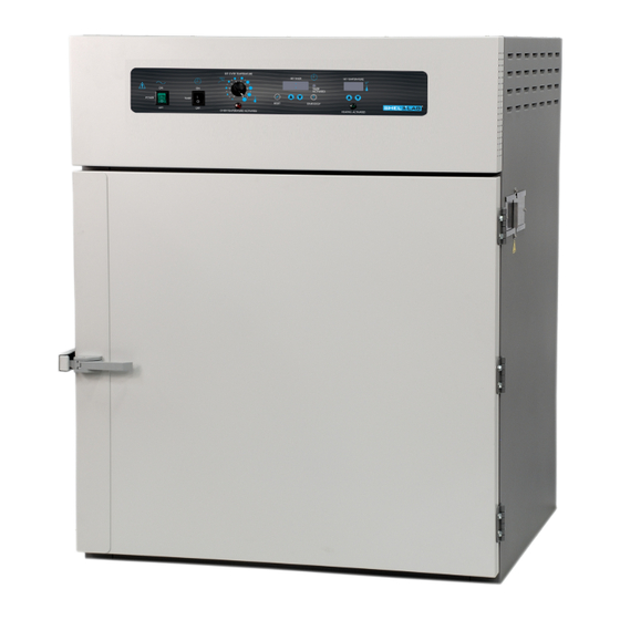
- Page 1 Forced Air Ovens 230 Voltage Installation and Operation Manual SMO14-2, SMO28-2 Previously designated as FX14-2, FX28-2...
-
Page 2: Installation And Operation Manual
SMO Forced Air Ovens 230 Voltage Previously designated FX Forced Air Ovens Installation and Operation Manual Part number (manual): 4861581 Revision: March 19, 2014 These units are TÜV CUE listed as forced air ovens for professional, industrial, or educational use where the preparation or testing of materials is done at approximately atmospheric pressure and no flammable, volatile, or combustible materials are being heated. -
Page 3: Table Of Contents
TABLE OF CONTENTS INTRODUCTION ............................4 General Safety Considerations ......................... 4 Engineering Improvements ........................4 Contacting Assistance ..........................5 RECEIVING YOUR OVEN ..........................6 Inspecting the Shipment ..........................6 Returning the Shipment ..........................6 Recording Data Plate Information ......................6 GRAPHIC SYMBOLS ........................... -
Page 4: Introduction
INTRODUCTION Thank you for purchasing a Sheldon Manufacturing SMO Forced Air Oven. We know that in today’s competitive marketplace, customers have many choices when it comes to constant temperature equipment. We appreciate you choosing ours. Our continued reputation as a leading laboratory product manufacturer rests with your satisfaction. -
Page 5: Contacting Assistance
INTRODUCTION (CONTINUED) ONTACTING SSISTANCE If you are unable to resolve a technical issue with your oven, please contact Sheldon Technical Support. Phone hours for Sheldon Technical Support are 6am – 4:30pm Pacific Coast Time (west coast of the United States, UTC -8). Please have the following information ready when calling or emailing Technical Support: the model number and the serial number (see page 6). -
Page 6: Receiving Your Oven
Included accessories Shelves Model Shelf Clips Leveling Feet SMO14-2 (FX14-2) SMO28-2 (FX28-2) Carefully check all packaging before discarding. Save the shipping carton until you are certain that the unit and its accessories function properly. ETURNING THE HIPMENT If you must return the oven for any reason, first contact your service representative for a return of material authorization (RMA). -
Page 7: Graphic Symbols
GRAPHIC SYMBOLS The oven is provided with multiple graphic symbols on the control panel and adjacent to the power inlet. The symbols identify hazards and the functions of the adjustable components, as well as important notes in the user manual. Symbol Definition Indicates that you should consult your service manual for further instructions. - Page 8 GRAPHIC SYMBOLS (CONTINUED) Symbol Definition Indicates the timer Indique le minuterie Start or Stop the Timer Lancer ou arrêter le minuteur Reset the Timer Réinitialisation de la Minuterie Indicates: Caution hot surface Indique: Avertissement symbole de surface chaude P a g e...
-
Page 9: Control Panel Overview
CONTROL PANEL OVERVIEW Figure 1: Control Panel SMO14-2 and SMO28-2 Power Switch The main power switch on the control panel (green lighted I/O) controls all power to the unit and must be in the I (ON) position before any systems are operational. The switch will be lighted when in the I (ON) position. - Page 10 CONTROL PANEL (OVERVIEW) Main Temperature Control Marked SET TEMPERATURE, this control consists of a green LED numerical display and an UP / DOWN arrow pad used for inputting set point temperatures and calibration offsets. Heating Activated Light The green pilot light labeled HEATING ACTIVATED illuminates whenever the oven heating elements are receiving power.
-
Page 11: Installation
INSTALLATION Installation of the unit requires permanent connect wiring (commonly known as hardwiring) and should be performed by a qualified electrical technician. All other steps can be performed by the end user. This oven is intended for use indoors, at room temperatures between 15C and 30C (59F and 86F), at no greater than 80% Relative Humidity (at 25C / 77F). -
Page 12: Power Source
OURCE These ovens are intended for a 230 volt, 50/60 Hz application at the following amperages: 12 Amp SMO14-2; 20 Amp SMO28-2. Check the oven’s data plate to verify voltage and ampere requirements before connecting to a power source. The oven’s power feed must be wired into an earth grounded source. Position the oven so the end- user has access to the power feed disconnect. -
Page 13: Shelving Installation
2. Squeeze each clip, insert the top tab first, and then the bottom tab using a rocking motion. 3. Hang the metal shelves from the clips. Figure 4: Shelving Clips SMO14-2 and SMO28-2 Rear Panel 13 | P a g e... -
Page 14: Cleaning
INSTALLATION (CONTINUED) LEANING The oven interior was cleaned at the factory but not sterilized. See the Cleaning topic in the User Maintenance section for more information. The oven should be run through a burning in process before being used for normal operations. This is done to eliminate smoking from the protective coatings on the oven’s heating elements. -
Page 15: Operation
OPERATION PERATING RECAUTIONS Warning : The SMO oven is not an explosion proof unit! The oven is not designed to safely contain combustible gasses. Do not place explosive, combustible, or flammable materials into the chamber. 1. The bottom surface of the chamber should not be used as a work surface 2. -
Page 16: Burn In: First Use
OPERATION (CONTINUED) IRST The steps below will help to eliminate smoking from the heating elements’ protective coatings. 1. If you have not already done so, turn the Over Temperature Control knob all the way clockwise to its maximum setting. 2. Open the unit’s exhaust vents. It is recommended that the oven’s exhaust be positively vented outside of the oven’s workspace during the Burn In. -
Page 17: Calibrating The Unit
OPERATION (CONTINUED) Note: Allow the oven to heat to up the set point, and then stabilize there with no change in the temperature reading for at least a half hour (30 minutes) prior to performing a Temperature Calibration. This is to ensure the best possible temperature uniformity in the oven chamber. Note: The open / close position of the dampered vents will affect the temperature performance of the oven when performing a calibration. -
Page 18: Setting The Over Temperature Limit Control
OPERATION (CONTINUED) 11. If the temperature readings of the display and the independent temperature device still do not match or fall close enough to be acceptable by your laboratory protocol after three calibration attempts, contact Sheldon Technical Support for assistance. ETTING THE EMPERATURE IMIT... -
Page 19: Setting The Timer
OPERATION (CONTINUED) ETTING THE IMER This procedure enters a timed heating cycle into the Timer. The cycle will run the oven for a set time, at the currently programed temperature set point. The oven will stop heating once the heating cycle is finished. -
Page 20: Activating The Heating Cycle
OPERATION (CONTINUED) CTIVATING THE EATING YCLE Note: The oven may be run in a timed heating cycle after a temperature set point has been set, the oven has been calibrated at that set point, and a heating cycle time period has been entered in the Timer. -
Page 21: User Maintenance
USER MAINTENANCE Warning : Prior to any maintenance or service on this unit, disconnect the power feed from the power supply. Avertissement : Avant d'effectuer toute maintenance ou entretien de cet appareil, débrancher le cordon secteur de la source d'alimentation. If a hazardous material/substance has spilled in the oven, immediately initiate your site’s Hazardous Material Spill Containment protocol. - Page 22 MAINTENANCE (CONTINUED) Periodically, inspect the door latch, trim, catch, and gasket for signs of deterioration. Failure to maintain the integrity of the door system shortens the life span of the Oven. Electrical components do not require maintenance. If the oven fails to operate as specified, please contact your Shel Lab distributor or Sheldon Manufacturing Technical Support for assistance.
-
Page 23: Unit Specifications
We reserve the right to alter technical specifications at all times. EIGHT Model Shipping Net Weight 360lbs. / 163kgs 280lbs. / 127kgs SMO14-2 (FX14-2) 495lbs. / 225kgs 390lbs. / 177kgs SMO28-2 (FX28-2) IMENSIONS By Inches Model Exterior W ×... -
Page 24: Shelf Capacity By Weight
UNIT SPECIFICATIONS (CONTINUED) HELF APACITY BY EIGHT Model Per Shelf Total SMO14-2 (FX14-2) 75lbs / 34kg 225lbs / 102kg SMO28-2 (FX28-2) 75lbs / 34kg 450lbs / 204kg EMPERATURE Model Range Uniformity Stability Ambient. +15 to SMO14-2 (FX14-2) + 3.0 @ 150C ±... -
Page 25: Parts List
PARTS LIST ARTS Description Parts Number Adjustable Feet 2700506 Shelf Clip 1250512 Shelf SMO14-2 (FX14-2) and SMO28-2 (FX28-2) 995-00006 25 | P a g e...
Need help?
Do you have a question about the SMO14-2 and is the answer not in the manual?
Questions and answers