shelolab SMO5HP-2 Installation And Operation Manual
High-perfomance oven 220-240 voltage
Hide thumbs
Also See for SMO5HP-2:
- Installation and operation manual (38 pages) ,
- Operation & installation manual (43 pages)
Table of Contents
Advertisement
Quick Links
Advertisement
Table of Contents

Related Manuals for shelolab SMO5HP-2


Summary of Contents for shelolab SMO5HP-2
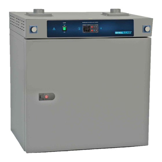
- Page 1 HIGH-PERFORMANCE OVEN 220 – 240 Voltage Installation - Operation Manual SMO5HP-2...
- Page 2 These ovens require permanent connect wiring (also known as hardwiring) to a power supply. Gas Purge Port Option The SMO5HP-2 can be built with a 3/8-inch ID (9.5mm) gas in-port on the back of the oven. This optional port can be connected to a cylinder of nitrogen (N ) or other inert gas to purge the oven chamber during baking applications.
- Page 3 SMO5HP-2 High-Performance Oven 220 – 240 Voltage Part Number (Manual): 4861706 Revision: June 23, 2020 Model SMO5HP-2 Part ID SLFHP522-H The Part ID denotes the build type of the model. The manufacturer periodically releases new build type designs incorporating new features and refinements of existing ones.
-
Page 4: Table Of Contents
TABLE OF CONTENTS INTRODUCTION ..............................5 Read this Manual ..................................5 Safety Considerations and Requirements ........................5 Contacting Assistance ................................6 Manufacturing Warranty ..............................6 Engineering Improvements ..............................6 Reference Sensor Device ..............................7 RECEIVING YOUR UNIT ............................9 Inspect the Shipment ................................9 Orientation.................................... -
Page 5: Introduction
INTRODUCTION Thank you for purchasing a SHEL LAB oven. We know you have many choices in today’s competitive marketplace when it comes to constant temperature equipment. We appreciate you choosing ours. We stand behind our products and will be here if you need us. EAD THIS ANUAL Failure to follow the guidelines and instructions in this user manual may create a protection... -
Page 6: Contacting Assistance
INTRODUCTION ONTACTING SSISTANCE Phone hours for Sheldon Customer Support are 6 am – 4:30 pm Pacific Coast Time (west coast of the United States, UTC -8), Monday – Friday. Please have the following information ready when calling or emailing Customer Support: the model number, serial number, part number, and part ID. See page 11. -
Page 7: Reference Sensor Device
INTRODUCTION EFERENCE ENSOR EVICE Must be purchased separately A reference sensor device is required for calibrating the unit temperature display. Reference devices must meet the following standards: Accurate to at least 0.1°C • Temperature The device should be regularly calibrated, preferably by a third party. Reference Temperature Probe Use a digital device with a wire thermocouple probe that can be introduced into the unit chamber... - Page 8 INTRODUCTION P a g e...
-
Page 9: Receiving Your Unit
RECEIVING YOUR UNIT NSPECT THE HIPMENT Safe delivery becomes the responsibility of the carrier when a unit leaves the factory. Damage sustained during transit is not covered by the manufacturing defect warranty. When you receive your unit, inspect it for concealed loss or damage to its interior and exterior. If you find any damage to the unit, follow the carrier’s procedure for claiming damage or loss. -
Page 10: Orientation
RECEIVING RIENTATION External Power Outlet: Varies by country and voltage type Fuse Holders SMO5HP-2 Power Panel - Back Purge Gas Inlet. 3/8 in ID Permanent Connect Wire Braid 14 gauge, 6 inches (150 mm) Control Exhaust Exhaust Vent Valve Control... -
Page 11: Recording Data Plate Information
RECEIVING ECORDING LATE NFORMATION Record the unit model number, serial number, part number, and part ID below for future reference. Customer Support needs this information to provide accurate help during support calls and emails. The data plate is located on the back of the oven, next to the power inlet. •... - Page 12 RECEIVING 12 | P a g e...
-
Page 13: Installation
INSTALLATION ARDWIRE EQUIREMENT The oven requires permanent connect wiring (commonly known as hardwiring). Wiring to the power source must be performed by a qualified electrical technician. All other Installation steps may be performed by the end-user. NSTALLATION ROCEDURE HECKLIST For installing the unit in a new workspace location. Pre-Installation ... -
Page 14: Required Ambient Conditions
INSTALLATION EQUIRED MBIENT ONDITIONS These units are built for use indoors at room temperatures between 15°C and 40°C (59°F and 104°F), at no greater than 80% Relative Humidity (at 25°C / 77°F). Operating outside these conditions may adversely affect the unit temperature performance. When selecting a location to install the unit, consider all environmental conditions that can adversely impact its temperature performance. -
Page 15: Power Source Requirements
INSTALLATION OWER OURCE EQUIREMENTS When selecting a location for the oven, verify that each of the following requirements is satisfied: Power Supply: The power supply must meet the power requirements listed on the unit data plate. Voltage Amperage Frequency 220 – 240 50/60 Hz The power source must be single phase and protective earth grounded. -
Page 16: Power Feed Wiring
INSTALLATION OWER IRING The oven comes provided with an integral 6-inch (150 mm) wire braid consisting of: 14-gauge high-temperature (300°C) hot wire – Black • 14-gauge high-temperature (300°C) hot wire – Red • 14-gauge earth ground wire – Green/Yellow • The wires for power source connection should be Green/Yellow –... -
Page 17: Leveling
INSTALLATION EVELING Install the 4 leveling feet in the corner holes in the bottom of the oven. The oven must be level and stable for safe operation. Note: To prevent damage when moving the unit, turn all 4 leveling feet so that the leg of each foot sits inside the unit. -
Page 18: Install The Shelving
INSTALLATION NSTALL THE HELVING The horizontal airflow within the chamber moves from the small duct holes on the right-hand side of the chamber to the large holes on the left side. Place the shelves so as not to obstruct the duct holes on either side. -
Page 19: Graphic Symbols
GRAPHIC SYMBOLS The unit is provided with graphic symbols on its exterior. These identify hazards and adjustable components as well as important notes in the user manual. Symbol Definition Consult the user manual. Consulter le manuel d'utilisation Indicates adjustable temperature Indique température réglable AC Power Repère le courant alternatif... - Page 20 SYMBOLS 20 | P a g e...
-
Page 21: Control Overview
CONTROL OVERVIEW Control Panel Power Switch The switch illuminates when in the ON ( I ) position. Temperature Controller – Display on Homepage Top Line (Red): Present chamber air temperature Middle Line (Green): The constant temperature setpoint Bottom Line: Flashing “1” indicates active heating While on the homepage, the Up and Down arrow buttons adjust the constant temperature setpoint. - Page 22 The EZ2 button has no function. Vent Valves The SMO5HP-2 comes with two vent valve controls on the front control panel. These open and close the intake and exhaust vents located on the top of the unit. Turn knobs counter-clockwise to close vents.
-
Page 23: Operation
OPERATION Safe operation of the oven is dependent on the actions and behavior of the oven operators. Operating personnel must read and understand the Operating Precautions in this section prior to operating the oven. The operators must follow these instructions to prevent injuries and to safeguard their health, environment, and the materials being treated in the oven, as well as to prevent damage to the oven. -
Page 24: Theory Of Operations
OPERATION HEORY OF PERATIONS Heating The oven temperature controller stores an end-user selected constant temperature setpoint. When powered, the oven heats the chamber atmosphere to the setpoint. The controller board is wired to a solid- state temperature probe located in the chamber on the right wall. When the controller detects that the chamber temperature has dropped below the temperature setpoint, it pulses power to the heating element. - Page 25 OPERATION Vents: Intake and Exhaust The oven is provided with intake and exhaust vent dampeners that may be opened or closed using controls on the front panel of the oven. The vent dampeners are intended to be opened after the heat treatment or bake out phases of an application are complete.
-
Page 26: Put The Oven Into Operation
OPERATION UT THE VEN INTO PERATION Perform the following steps and procedures to put the unit into operation after installing it in a new workspace environment. Power the Oven Place the oven Power Switch in the ON ( I ) position. The controller display will illuminate, show the current •... -
Page 27: Set The High Temperature Limit
OPERATION ET THE EMPERATURE IMIT Note: Test the high limit system once per year for functionality. The high-temperature limit is set by the end-user, typically at 10°C above the highest temperature the oven will run during your recipe program or constant-temperature application. Advance to the Limit High Setpoint, starting on the homepage Push the Advance button repeatedly until “Lh.S1”... -
Page 28: Set The Constant Temperature Setpoint
OPERATION ET THE ONSTANT EMPERATURE ETPOINT Adjust the Constant Temperature Setpoint on the Homepage Stay 10°C below the high limit • setpoint. Note: Holding down an arrow button will cause the temperature to advance in increments of ten (10). Adjust Release the Arrow buttons after adjusting the Setpoint There may be a brief pause as the oven controller •... -
Page 29: High Temperature Limit Activated
OPERATION EMPERATURE IMIT CTIVATED The High Limit system blocks heating in the oven chamber if the chamber temperature meets or exceeds the present High Limit setting. Heating remains disabled until the High Limit cutoff is manually cleared by the oven end-user. Alternating Alert Screens Indicators Two alternating alert screens flash when a High Limit cutoff is active. -
Page 30: Venting Oven Exhaust
OPERATION ENTING XHAUST Optional: The oven does not require venting to operate. However, evacuating exhaust out of the workspace can help prevent elevated temperatures and the buildup of unpleasant odors. Obtain flexible, non-insulated ducting. • Attach the ducting to the lip of the exhaust port on the top, right side of the oven. See the •... -
Page 31: Power Exhaust Blower
OPERATION OWER XHAUST LOWER Note: Exposure to sustained oven chamber temperatures above 80°C will damage the exhaust blower while it is turned off. Leave the oven exhaust vent dampener closed until it is time to turn on the blower and actively vent the oven chamber. SHEL LAB offers an accessory forced-air power exhaust blower that can be mounted directly on the exhaust vent cover. - Page 32 OPERATION Continued from the previous page Activating the Power Exhaust Blower The exhaust blower can be activated either as part of a heating recipe program or manually from the homepage Options menu while running a constant temperature setpoint. Manually Turning on the Exhaust Blower Advance to the homepage Event parameter.
-
Page 33: User Maintenance
USER MAINTENANCE Warning: Disconnect the unit from its power supply prior to maintenance or cleaning of this unit. Avertissement: Avant d'effectuer toute maintenance ou entretien de cet appareil, débrancher le cordon secteur de la source d'alimentation. LEANING AND ISINFECTING Periodic cleaning is required. •... -
Page 34: Door Gaskets And Chamber Integrity
MAINTENANCE Disinfecting Disinfect the oven if algae, mold, bacteria, or other biological contaminants are an issue. For maximum effectiveness, disinfection procedures are typically performed after cleaning. Keep the following points in mind when disinfecting the oven: Turn off and unplug the unit to safeguard against electrical hazards. •... -
Page 35: Removing The Chamber Liner
MAINTENANCE EMOVING THE HAMBER INER The chamber liner and ducts should be removed periodically and cleaned, and the surfaces beneath them cleaned. Note: Door removed in illustrations for clarity. Do not remove the door from the oven. Remove all shelves and shelf sliders from the oven. 2. -
Page 36: Calibrating The Temperature Display
MAINTENANCE ALIBRATING THE EMPERATURE ISPLAY Note: Performing an accurate calibration of the temperature display requires a temperature reference device. Please see the Reference Sensor Devices entry on page 7 for the minimum device requirements. Temperature calibrations match the temperature display to the actual air temperature inside the oven chamber. - Page 37 MAINTENANCE 7. The oven temperature must be stable in order to perform an accurate calibration. The temperature is considered stabilized when the oven chamber has operated with the door closed at your calibration temperature for at least one hour with no fluctuations greater than the specified stability of the oven (see page 41).
- Page 38 MAINTENANCE Calibration continued Navigate to the Operations menu. a. Press and hold both the Up and Down arrow buttons simultaneously for approximately 5 seconds. b. Release the buttons when “A1” appears on the top display line and “oPEr” appears in the mid display line. Operations Menu Advance through the Operations menu options to the Temperature Calibration offset parameter.
- Page 39 MAINTENANCE Calibration continued Allow the oven to stabilize after achieving the temperature setpoint using the offset display value. Note: The unit is stabilized when no fluctuations of ±0.2°C or greater are detected. Reference Device Once the chamber has stabilized, compare the reference temperature device and oven temperature display readings.
- Page 40 MAINTENANCE 40 | P a g e...
-
Page 41: Unit Specifications
UNIT SPECIFICATIONS The SMO5HP-2 is a 220 – 240 voltage unit. Please refer to the unit data plate for individual electrical specifications. Technical data specified applies to ovens with standard equipment at an ambient temperature of 25°C and nominal voltage. The temperatures specified are determined in accordance with factory standard following DIN 12880 respecting the recommended wall clearances of 10% of the height, width, and depth of the inner chamber. -
Page 42: Airflow Performance
SPECIFICATIONS Uniformity @80°C @150°C @306°C + 1.0°C + 2.0°C + 3.5°C Time to Temperature: From an ambient temperature of 20°C. Heating Time to 80°C Heat Up Time to 150°C Heat Up to 306°C 10 minutes 22 minutes 35 minutes Recovery Time: From a 30-second door opening. Recovery to 80°C Recovery to 150°C Recovery to 306°C... -
Page 43: Replacement Parts
REPLACEMENT PARTS Description Parts Number Description Parts Number Fuse, Accessory Outlet, 2 amp, 250V, Adjustable Foot 5x20mm. Requires 2 fuses. 3300502 2700512 Silicone Chamber Gasket (unit of sales is Shelf Slide per foot, requires 11 feet) 3450546 5121189 Silicone Door Gasket (unit of sales is per Shelf foot, requires 11 feet) - Page 44 P.O. Box 627 Cornelius, OR 97113 support@sheldonmfg.com sheldonmanufacturing.com 1-800-322-4897 (503) 640-3000 FAX: 503 640-1366...
Need help?
Do you have a question about the SMO5HP-2 and is the answer not in the manual?
Questions and answers