Advertisement
Quick Links
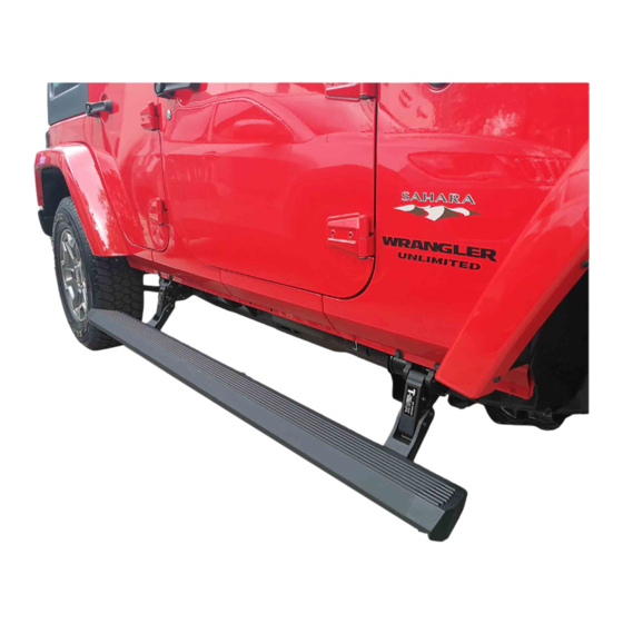
JEEP WRANGLER POWER BOARD
JEEP WRANGLER POWER BOARD
Product Number :PST01-0110/PST01-0130
PST01-0210/PST01-0230
APPLICATION :2012-UP
Tools Required :
q
www.tmax.biz
JEEP WRANGLER
POWER BOARD
INSTALLATION
GUIDE
INSTALLATION TIME
① 5mm Hex Key Wrench (Allen Wrench)
② 13mm Socket Spanner
p
③ 18mm Socket Spanner
⑤ Cable Stripper/Cutter
⑦ Electric Hand Drill
④ Vinyl Tape
⑥ Scissors
⑧ φ10 Drilling Bit
Advertisement

Subscribe to Our Youtube Channel
Related Manuals for T-MAX E-BOARD PST01-0110


Summary of Contents for T-MAX E-BOARD PST01-0110
- Page 1 JEEP WRANGLER POWER BOARD JEEP WRANGLER POWER BOARD JEEP WRANGLER POWER BOARD INSTALLATION GUIDE INSTALLATION TIME APPLICATION :2012-UP ① 5mm Hex Key Wrench (Allen Wrench) Tools Required : Product Number :PST01-0110/PST01-0130 ② 13mm Socket Spanner ③ 18mm Socket Spanner ④ Vinyl Tape PST01-0210/PST01-0230 ⑤...
-
Page 2: Table Of Contents
Product Packing List.........03 Mechanical Installation......08 Electrical Installation........29 Maintenance..........30 Warranty Card...........32 The product is developed and produced by T-MAX and the related patents are blow The product is developed and produced by T-MAX, and the related patents are blow. Patents:US8,469,380;US9,656,609;US9,308,870;US9,688,205;US9,669,766 www.tmax.biz... -
Page 3: Product Technical Specification
JEEP WRANGLER Product Technical Specification Rated Voltage: 12V Specified Load: ≤300kg Board Length: 2D Length including end caps: 1.33m, 2D Length without end caps: 1m without end caps: 1m 4D Length including end caps: 1.86m, 4D Length without end caps: 1.53m Gross Weight: 20.5kg(2D)/ 27kg(4D)... -
Page 4: Product Packing List
JEEP WRANGLER Product Packing List ① Board Assembly JP4×2 6124101 2 ① - Board Assembly JP4×2 6124101.2 Board Assembly JP2×2 6124100.2 ⑤ - Rear Motor Linkage Right4D×1 ④ - Rear Motor Linkage Left 4D×1 6124101.1RB ② - Front Motor Linkage Left ×1 ③... - Page 5 JEEP WRANGLER ⑧ - Spring Washer×2 GB/T93-1987 12 ⑥ - Motor Protective Plate Left ⑦ - Motor Protective Plate Right ⑨ - Flat Washer Grade A×2 JP-L×1 JP-R×1 GB/T96.1-2002 12 6124100.0-2L 6124100.0-2R ⑪ - Spring Washer ⑩ - Flat Washer×2 ⑫- Flat Washer Grade A GB/T95-1985 8 GB/T93-1987 8...
- Page 6 JEEP WRANGLER ⑬ - Mounting Plate Left JP2-L×1 6124110.0-3L ⑭ - Mounting Plate Right JP2-R×1 6124110.0-3R (Special for 2D) (Special for 2D) ⑰ -Hexagon Head Bolt×2 ⑯ - Hexagon Head Bolt GB/T5781-86 M8×25 GB/T5781-86 M8×20 ⑮ - Socket Cap Screw ×8 ⑱...
- Page 7 JEEP WRANGLER - Hex Nut ×2 N t ×2 - Mounting Plate JP4×2 6124100.0-1 GB/T 6170-2000 M8 (Special for 4D) (Special for 2D) - Posi-lock connector - Cable Tie×25 - Power Board Switch ×1 -Fuse×2 (For signal cable connection) GB/T22344-2008 5×300 6124151.4.9 5 .
- Page 8 JEEP WRANGLER Thick magnet Magnet Magnet - Wired Magnetic Induction Module×2 Wi d M i I d M d l ×2 -Controller Assembly×1 -Magnet×4 (4D × 4) 6124100.4.4ZJ Note: The normal magnets are for the front doors ,and the thicker ones are for the rear doors. -Magnet×2 (2D ×...
- Page 9 JEEP WRANGLER Protection tube for high temperature and burning Two-core plug (red) Four-core waterproof plug Two-core plug (black) Six-core waterproof plug (Negative-Black) d) ( (Positive-Red) - Control Input Wire ×1 6124100.4.1 www.tmax.biz...
-
Page 10: Mechanical Installation
JEEP WRANGLER Mechanical Installation Mechanical Installation Front Motor Linkage Front Motor Linkage Rear Motor Linkage Front Motor Linkage Rear Motor Linkage Right JP-RF Right JP4/2-RB Left JP-LF Left JP4/2-LB Graph of Motor Linkage Graph of Motor Linkage www.tmax.biz... - Page 11 JEEP WRANGLER 1. Mounting plate installation 2. Tighten bolt for mounting plate 3. Tighten bolt for linkage 4. Board installation Stud Bolt A M8 Tension Block Step 2: Screw the stud bolt A. Step 1: Shown as picture, insert the M8 tension block. www.tmax.biz...
- Page 12 JEEP WRANGLER Mounting Plate JP4 ⑫ Φ8 Flat ⑫ Φ8 Flat Washer Grade A Washer Grade A ⑪ Φ8 Spring ⑪ Φ8 Spring Washer Washer ⑩ Φ8 Flat ⑱ M8×35 Hexagon Head Bolt M8 Hex Washer ⑪ Φ8 Spring Washer ⑰...
- Page 13 JEEP WRANGLER Drilling Front Position 2D New drilling hole for installing New drilling hole for installing Original hole as the base Original hole for motor linkage installing motor linkage As shown in the picture, drill a new hole on the side skirt based on the original hole (Dia of new hole is 8.5mm-9.5mm). Please adjust the hole position due to different vehicles.
- Page 14 JEEP WRANGLER ⑫ M8×20 Hexagon Head Bolt Step 8: As shown in the picture, tighten the hexagon head bolt in Step 9: As shown in the picture, tighten the hexagon head bolt the step 6 to install the motor linkage (Tighten Torque 23Nm) . (Tighten Torque 23Nm) .
- Page 15 JEEP WRANGLER ⑯M8×20 Hexagon Head Bolt Step 12: As shown in the picture, tighten the hexagon head bolt in Step 13: As shown in the picture, tighten the hexagon head bolt. the step 10 to install the motor linkage. (Tighten Torque 23Nm) (Tighten Torque 23Nm) Light belt socket Light belt insert...
- Page 16 JEEP WRANGLER Note: Put pin of motor protective plate JP-L into this hole. ⑥Motor Protective ⑥Motor Protective Plate JP-L ⑨Φ12 Flat Washer Grade A ⑧Φ12 Spring Washer ⑧ ⑲M12×35 Hexagon Head Bolt ⑳M12 Tensioning Block Step 16: Install motor protective plate JP-L according to above picture.
- Page 17 JEEP WRANGLER Status of Power Board Get Back www.tmax.biz...
- Page 18 JEEP WRANGLER El t i Electric Installation of Magnetic Control 4.Connect white and brown signal wire Power with wired magnetic induction module . Board 1. Pull out the fuse and Switch connect the battery wire. 2. Connect the control wire and arrange all function wires to the pointed positions. t th t l i ll f...
- Page 19 JEEP WRANGLER Front Battery Front Rear Right Front Front Right Right Front Front Left Right Controller Front Left Rear Rear Left Rear Right Left Left side (upward view) Figure 1 Figure 2 Figure 1 is the wire harness diagram and figure 2 is the installation diagram. When install the wire harness, make sure the four connectors are connected with the four motor linkages by “f “front left,rear left,front right and rear right”.
- Page 20 JEEP WRANGLER Φ8 Spring Washer Φ8 Larger Washer Grade A M8×20 Hexagon Head Bolt Controller Assembly I t ll th Install the controller assembly as shown in the picture, tighten bolts (Tighten torque is 30Nm). t ll i th ti ht b lt (Ti ht i 30N ) The installation of controller assembly for 2D refers to 4D.
- Page 21 JEEP WRANGLER Front Chassis on the right Step 2:The arrangement of motor wire and LED lamp wire: Arrange the motor connection wire along the beam as shown in the picture, the motor wire plug extends to motors of linkage. At least , adjust the wire harness to make sure i i id it is tidy and beautiful.
- Page 22 JEEP WRANGLER White signal wire and Brown signal wire power board switch wire A -pillar panel Figure 2 Power board switch Sill panel Sill panel Figure 3 Figure 1 Step 3: Connection of signal wire: Pry the sill panel and A-pillar panel on the left above . Pull the brown signal wire into the vehicle through the rubber grommet of chassis on the right side Then the white signal wire extends to the left side of the vehicle under the through the rubber grommet of chassis on the right side.
- Page 23 JEEP WRANGLER Magnetic Inductor Installation for 2D Vehicle Induction part C Wire Harness Magnetic Inductor B-Pillar on the right side (open the cover plate) Earthing stud of pillar (Negative) Tear off the double-sided Tighten the nut connecting adhesive tape at the back of Insert the door signal cable Insert the door signal cable B and ground terminal of...
- Page 24 JEEP WRANGLER Magnetic Inductor Installation for 4D Vehicle Induction part C Induction part C Wire Harness Magnetic Inductor B-pillar on the right side (open the B-pillar panel) Earthing stud D (Negative) Remove the double-sided adhesive tape at the back of Tighten the nut connecting Insert the door signal wire C, and stick one end on one...
- Page 25 JEEP WRANGLER Vehicle Door Signal Cable Installation Signal cable Vehicle cable harness Purple and white cable Purple and yellow cable Long brown signal cable Purple and gray cable Short brown signal cable Usage of posi-lock connector i l k Short white signal cable Connect the signal cable by posi-lock connector, shown as right picture, find out the purple and gray cable, and connect to the short white signal cable.
- Page 26 JEEP WRANGLER Step 6:Sort out the wire harness and close the panels. The installation of white signal wire on the left side is same with the right side . www.tmax.biz...
- Page 27 JEEP WRANGLER Step 7: Installation of LED lamp : Tear off the double-sided adhesive tape behind the LED lamp and stick it to the thin wall blow the apron. The distance from designated pasting position of front and rear LED lamp to distance from designated pasting position of front and rear LED lamp to front door line of front door is shown as the picture (The distance of the front lamp is 550mm, and the rear lamp is 1600mm).
- Page 28 JEEP WRANGLER S mmar of Electric Part Summary of Electric Part Wired magnetic induction module arrangement Battery Power board Signal wire Motor wire switch arrangement arrangement Motor wire connection Controller Controller Pull signal wire and power board switch into the vehicle Step9.1: Check out the power board switch of controller to make sure it is off.
- Page 29 JEEP WRANGLER S mmar of Electric Part Summary of Electric Part Power Power board Battery switch Signal wire arrangement Motor wire connection Controller Controller Pull signal wire and power board switch into the vehicle Signal cable installation position Vehicle Door Signal Cable Installation Step9.2: Check out the power board switch of controller to make sure it is off.
-
Page 30: Electrical Installation
JEEP WRANGLER Instructions of Power Board Switch Stick the power board switch with 3M tape under the left side of steering wheel. I. Function of power board switch Turn off the switch when no need of power board or inconvenience of power board , then the power board will automatically get back and stop working to avoid any impact when use the vehicle . -
Page 31: Maintenance
JEEP WRANGLER Maintenance Inspect the normal operation of the mechanism. 3 months Periodical Inspect damage for each cable connection and the bare part outside of the vehicle beam. Inspection Inspect screw’s looseness of motor and power board . Clean the sediment on time for power board and the linkages. Special Case Inspection Clean the ice on time for power board and the linkages. - Page 32 I Maintenance Instruction I Maintenance Instruction 1、During warranty period, T-MAX provides free maintenance for any malfunction related to the manufacturer. Warranty period lasts 24 months or 50 thousand kilometers in 2 years after sale. For individual related faults, T-MAX provides paid maintenance.
-
Page 33: Warranty Card
① Electrical fault: the connection point and line failure, the gate control trigger line failure, controller failure, the electrical motor cable failure, motor failure; send to local T-MAX Terminal Services branch to detect and repair. ② Mechanical faults: a foreign object obstruction pedal movement, the i t ll ti installation of two pedal mounting surfaces is not at the same level;... - Page 34 Produced by T-MAX(HANGZHOU)TECHNOLOGY CO.,LTD www.tmax.biz...
Need help?
Do you have a question about the E-BOARD PST01-0110 and is the answer not in the manual?
Questions and answers
Where in melbourne can i buy a control unit?