Table of Contents
Advertisement
Quick Links
OWNER`S MANUAL
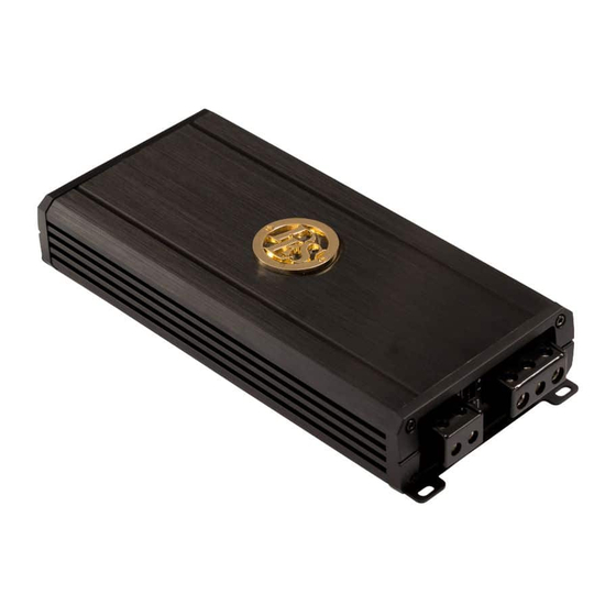
DD33-40
600W /3 Channel Audiophile cool running Digital Amplifier
This product must be returned to the
separate collection system for electronic
products. Do not dispose this product
together with general household waste.
DD-SERIES
DLS amplifiers are designed and engineered by:
DLS Svenska AB
Tagenevägen 11B
42259 Hisings Backa / Sweden
Tel: +46 31 840060
E-mail: info@dls.se
www.dls.se
Advertisement
Table of Contents

Related Manuals for DLS DD Series


Summary of Contents for DLS DD Series
- Page 1 OWNER`S MANUAL DD-SERIES DD33-40 600W /3 Channel Audiophile cool running Digital Amplifier DLS amplifiers are designed and engineered by: DLS Svenska AB This product must be returned to the Tagenevägen 11B separate collection system for electronic 42259 Hisings Backa / Sweden products.
-
Page 2: Warranty Service
Thank you and congratulations Thank you for your decision to purchase a DLS amplifier! Your DLS amplifiers must be installed correctly to perform at its best. This manual will show you how to install the amplifier like a pro. Please read the entire manual before beginning the installation. -
Page 3: Mounting The Amplifier
In the event of overheating, the amplifier will turn off and only restart when cooled. For this reason the amplifier should be mounted in a location which will allow air to circulate freely. The compact size of the DLS DD Series amplifier allows greater flexibility in mounting. - Page 4 DD33-40 CONTROL PANEL LAYOUT Fig. 2 - 3 Channel Panel Layout 1. SUBWOOFER INPUT Connector This is both a Low and High Level Input port. Using the supplied wiring harness for low level RCA inputs or as instructed on Fig.9 High Level (speaker level) input. 2.
- Page 5 6. INPUT Switch Matches the input from the Source Unit to that of the amplifier, either 2 or 3 Channel with separate subinput. This eliminates the use of “Y” adapters and provides a cleaner input signal. When the 2-Channel mode is selected, both front and sub outputs will operate from front low level RCA / high level input.
- Page 6 Your DLS DD amplifier requires unrestricted current to deliver peak performance, so do not “starve” your amplifier by using small power cable. Using under sized power cable can result in unnecessary over-heating of the amplifier, distortion at high volume levels and might even cause the thermal protection circuitry to shut off the amplifier.
-
Page 7: Power Wiring
POWER WIRING BATT+ (Power) This amplifier should be wired directly to the vehicle battery using the appropriate size cable. Start at the vehicle battery and run the power cable through to the amplifier. Avoid running the power cable over engine components and near heater cores. The use of an inline fuse or circuit breaker is a must;... - Page 8 REM (Remote Trigger) This terminal must be connected to a switched +12V- source.Typically, remote turn -on leads are provided at the source unit that will turn on and off the amplifier in correspondence with the source. If the source unit does not have a remote turn-on lead, then a switched +12V supply must be used, like the ACC, +12V Run a minimum of 18 gauge wire from the amplifier location to the source of the switched +12V lead.
-
Page 9: Fuse Requirements
FUSE REQUIREMENTS Due to the small size of the DLS DD series amplifiers, no fuses are incorporated into the panels that normally protect the unit from excessive current. Use an in-line fuse holder and fuse for this purpose. Remember this fuse also protect the vehicle/vessel from a dangerous short circuit. - Page 10 SOURCE INTERCONNECT Single RCA / Low Level Input Fig.7a Input using Single RCA or 3.5mm AUX Cable Choose the correct length and style of RCA interconnects for your needs. Always use high quality RCA audio cables (not supplied) for signal connections—those with multiple layers of shielding or a twisted pair variety for better noise rejection.
- Page 11 SOURCE INTERCONNECT Dual RCA / Low Level Input (Front and Subwoofer) Fig.8 Input using two pairs of RCA cables...
- Page 12 SOURCE INTERCONNECT Single High Level / Speaker Input White (Solid) = Left + White / Black (Striped) = Left - Grey (Solid) = Right + Grey / Black (Striped) = Right - Fig.9 High Level / Speaker Level Input 1) To use speaker level inputs please connect the HLC harness to connector, 2) Connect the wires from the speaker output of the radio to the white and grey wires of the amplifier input wires using the color codes in above drawing.
-
Page 13: Set-Up Adjustments
SET UP ADJUSTMENTS INPUT Gain Adjustment GAIN Control Panel (3) and (11) GAIN Control M AX This control allows you to match the input level of the amplifier to the output level of your head unit. Matching the input can be accomplished in three simple steps: Set the volume of GAIN on the amplifier to Min (completely counter clock wise). -
Page 14: Input Switch
Control Panel (6) High Pass Control (HPF) 400H HPF (High Pass Filter) Adjustment When you are using coaxial or component speaker system, this allows you to adjust high-pass X-over frequency from 40Hz to 400Hz. To get better sound quality from coaxial or component speaker system, we recommend the frequency should be higher than 80Hz. -
Page 15: Speaker Load
Speaker Load Keep in mind your DLS DD33-40 amplifier is a high power amplifier and not a high current amplifier. In other words this amplifier requires a minimum impedance of 2 ohms STEREO and 4 ohms bridged (2-ohms MONO on SUB channel) to operate trouble free Lower. - Page 16 PLEASE OBSERVE POLARITY AS SHOWN ON WIRE MARKERS. Speaker Output Connections 3 Channel Model (DD33-40) 3-Channel Speaker Output Connection Fig.12 3-CH Speaker Connection (Do not connect total impedance under 2 ohms)
-
Page 17: Troubleshooting Tips
NOTE: After using all the troubleshooting tips above, if the Status L.E.D. is activated and glows RED with no speakers connected to the amplifier, and all the power connections are correct, this would indicate an internal problem with the amplifier. Contact DLS Sweden or your local dealer... -
Page 18: Specifications
Specifications DD33-40 Number of channels Amplifier class 95Wx2+300W Power output RMS, 2 ohm (1%THD) Peak music power, 2 ohm 490 W Power output RMS, 4 ohm (1%THD) 75Wx2+200W Signal to noise ratio, A-weighted >90 dB >80 Damping factor 10 Hz - 20 kHz Frequency response Input impedance, low level 22 kohm...
Need help?
Do you have a question about the DD Series and is the answer not in the manual?
Questions and answers