Advertisement
Y our generator has been engineered and manufactured to our high standard for dependability, ease of operation, and operator
safety. When properly cared for, it will give you years of rugged, trouble-free performance.
WARNING:
To reduce the risk of injury, the user must read and understand the operator's manual before using this
product. If you do not understand the warnings and instructions in the operator's manual, do not use this product.
SAVE THIS MANUAL FOR FUTURE REFERENCE
Ce groupe portable a été conçu et fabriqué conformément à
nos strictes normes de fiabilité, simplicité d'emploi et sécurité
d'utilisation. Correctement entretenu, cet outil vous donnera des
années de fonctionnement robuste et sans problème.
AVERTISSEMENT :
Pour réduire les risques de blessures, l'utilisateur doit
lire et veiller à bien comprendre le manuel d'utilisation
avant d'employer ce produit. Si tous les avertissements
et toutes les consignes de sécurités et instructions du
manuel d'utilisation ne sont pas bien compris, ne pas
utiliser ce produit.
CONSERVER CE MANUEL POUR
FUTURE RÉFÉRENCE
To register your RIDGID
product, please visit:
http://register.RIDGID.com
Pour enregistrer votre
produit de RIDGID,
s'il vous plaît la visite:
http://register.RIDGID.com
Para registrar su producto
de RIDGID, por favor visita:
http://register.RIDGID.com
NEUTRAL BONDED TO FRAME
(CONNECTEUR NEUTRE RELIÉ AU CADRE, PUNTO NEUTRO CONECTADO AL MARCO)
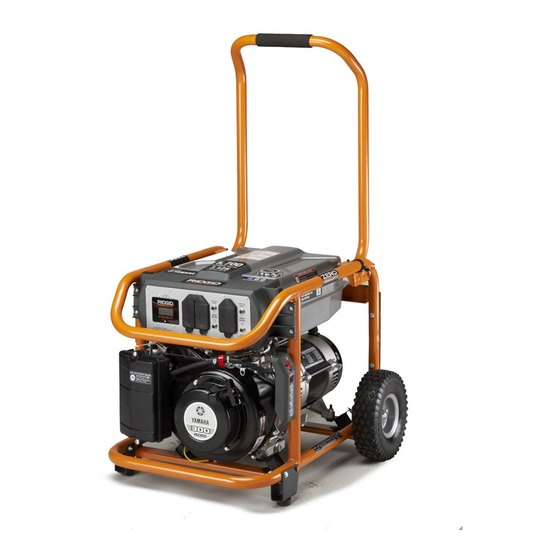
OPERATOR'S MANUAL
PORTABLE GENERATOR
Su generador portàtil diseñado y fabricado de conformidad con
nuestras estrictas normas para brindar fiabilidad, facilidad de uso
y seguridad para el operador. Con el debido cuidado, le brindará
muchos años de sólido funcionamiento y sin problemas.
ADVERTENCIA:
Para reducir el riesgo de lesiones, el usuario debe leer y
comprender el manual del operador antes de usar este
producto. Guarde este manual del operador y estúdielo
frecuentemente para lograr un funcionamiento seguro y
continuo de este producto.
GUARDE ESTE MANUAL PARA
FUTURAS CONSULTAS
Manuel de l'opérateur
Manual del operador
Générateur portative
Generador portàtil
RD905712
Series / Série / Serie
DO NOT USE E15 OR E85 FUEL IN THIS UNIT.
IT IS A VIOLATION OF FEDERAL LAW AND
WILL DAMAGE THE UNIT AND VOID YOUR
WARRANTY.
NE PAS UTILISER D'ESSENCE E15 OU E85
DANS CET APPAREIL. UNE TELLE UTILISATION
REPRÉSENTE UNE VIOLATION DE LA LOI
FÉDÉRALE ET ENDOMMAGERA L'APPAREIL ET
ANNULERA LA GARANTIE.
NO UTILICE COMBUSTIBLES E15 O E85 EN
ESTA UNIDAD. ESTO CONSTITUYE UNA
VIOLACIÓN A LA LEY FEDERAL, DAÑARÁ LA
UNIDAD Y ANULARÁ LA GARANTÍA.
Advertisement
Table of Contents

Related Manuals for RIDGID RD905712 Series


Summary of Contents for RIDGID RD905712 Series
- Page 1 Générateur portative Para registrar su producto Generador portàtil de RIDGID, por favor visita: http://register.RIDGID.com RD905712 Series / Série / Serie DO NOT USE E15 OR E85 FUEL IN THIS UNIT. IT IS A VIOLATION OF FEDERAL LAW AND WILL DAMAGE THE UNIT AND VOID YOUR WARRANTY.
- Page 2 See this fold-out section for all of the figures referenced in the operator’s manual. Consulter l’encart à volets afin d’examiner toutes les figures mentionnées dans le manuel d’utilisation. Consulte esta sección desplegable para ver todas las figuras a las que se hace referencia en el manual del operador.
- Page 3 Fig. 1 A - Reset button (bouton de réinitialisation, botón de reajuste) B - Test button (bouton de test, botón de prueba) Fig. 2 A - Recoil starter grip (poignée du démarreur à O - Oil cap/dipstick (bouchon/jauge d’huile, H - 120 volt AC GFCI 20 amp receptacles [prises rappel, mango del arrancador retráctil) tapa de relleno de aceite/varilla medidora de 120 V C.A.
- Page 4 Fig. 3 1 - Axle bolt (essieu, eje) 5 - Screw (vis, tornillo) 8 - Nut (écrou, tuerca) 2 - Wheel (roue, rueda) 6 - Washer (rondelle, arandela) 9 - Engine lubricant (lubrifiant de moteur, 3 - Washer (rondelle, arandela) 7 - Leg with rubber foot (pied avec patin en lubricante para motor) 4 - Lock nut (écrou de blocage, tuerca de...
- Page 5 Fig. 7 Fig. 10 120V 240V AC/CA AC/CA MAINTENANCE CIRCUIT CIRCUIT BREAKER BREAKER Load Indicator measures 240V AC/CA 120V AC/CA GFCI outlets only NOT GFCI PROTECTED 120V 120V 240V AC/CA GFCI AC/CA GFCI 30A AC NEUTRAL BONDED TO FRAME A - GenSmart™ monitoring system (système de surveillance GenSmart™, sistema de monitoreo GenSmart™) B - 120 volt AC 20 amp GFCI receptacles [prises 120 V C.A.
- Page 6 Fig. 13 Fig. 16 A - Handle lock pin (goupille de blocage de la poignée, pasador de seguro del mango) B - Joined area (partie jointe, área acoplada) Fig. 14 A - Off switch (interrupteur arrêt de moteur, interruptor encendido/apagado del motor) Fig.
- Page 7 Fig. 18 Fig. 21 Fig. 22 A - Carburetor drain screw (vis de vidange A - Oil cap/dipstick (bouchon/ jauge d’huile, du carburateur, tornillo de drenaje del tapa de relleno de aceite/varilla medidora de carburador aceite) B - Oil fill hole (orifice de remplissage d’huile, Fig.
-
Page 8: Table Of Contents
TABLE OF CONTENTS Introduction ..................................2 Important Safety Instructions ............................3-4 Specific Safety Rules ..............................4 Symbols ..................................5-7 Electrical ..................................7-9 Features ..................................10 Assembly ..................................11-12 Operation ..................................13-15 ... -
Page 9: Important Safety Instructions
IMPORTANT SAFETY INSTRUCTIONS Never start or run the engine inside a closed or partially DANGER: enclosed area. Breathing exhaust fumes will kill you. Carbon Monoxide. Using a generator indoors CAN Keep all bystanders, children, and pets at least 10 feet KILL YOU IN MINUTES. -
Page 10: Specific Safety Rules
IMPORTANT SAFETY INSTRUCTIONS Maintain the unit per maintenance instructions in this Inspect the unit before each use for loose fasteners, fuel Operator’s Manual. leaks, etc. Replace damaged parts. SPECIFIC SAFETY RULES Do not operate generator at a gas or natural gas filling WARNING: station. -
Page 11: Symbols
SYMBOLS The following signal words and meanings are intended to explain the levels of risk associated with this product. SYMBOL SIGNAL MEANING Indicates an imminently hazardous situation, which, if not avoided, will result DANGER: in death or serious injury. Indicates a potentially hazardous situation, which, if not avoided, could result WARNING: in death or serious injury. - Page 12 SYMBOLS Some of the following symbols may be used on this product. Please study them and learn their meaning. Proper interpretation of these symbols will allow you to operate the product better and safer. SYMBOL NAME DESIGNATION/EXPLANATION Hertz Frequency (cycles per second) Watt Power Hours...
-
Page 13: Electrical
SYMBOLS FUEL WARNING No smoking when filling with gasoline. Do not overfill. Full level is 1 in. below the top of the fuel neck. Stop the engine for five minutes before refueling to avoid the heat from the muffler igniting fuel vapors. ENGINE LUBRICANT WARNING You must add lubricant before first operating the generator. - Page 14 ELECTRICAL ELECTRIC MOTOR LOADS It is characteristic of common electric motors in normal operation to draw up to six times their running current while starting. This table may be used to estimate the watts required to start electric motors; however, if an electric motor fails to start or reach running speed, turn off the appliance or tool immediately to avoid equipment damage.
- Page 15 ELECTRICAL 3. Permit the generator output to stabilize (engine runs 3. Estimate how many surge (starting) watts you will need. smoothly and attached device operates properly). Surge wattage is the short burst of power needed to start electric motor-driven tools or appliances such as a 4.
-
Page 16: Features
FEATURES PRODUCT SPECIFICATIONS ENGINE GENERATOR Engine Type .......Yamaha MZ300, 4 Stroke, OHV Rated Voltage .............120V/240V Rated Amps ........... 47.5A/23.75A Bore x Stroke ..........85 mm x 63 mm Rated Output ............5,700 W Cooling System ...........Forced Air Maximum Output............7,125 W Compression Ratio ............8.1:1 Rated Frequency ............60 Hz Starting System ............ -
Page 17: Assembly
ASSEMBLY UNPACKING WARNING: This product requires assembly. If any parts are damaged or missing do not operate Carefully cut the box down the sides then remove the this product until the parts are replaced. Use of machine and any accessories from the box. Make sure this product with damaged or missing parts could that all items listed in the Loose Parts are included. - Page 18 ASSEMBLY LOOSE PARTS LIST Raise the front end of the generator, where the engine is located, high enough to gain access to the frame bottom; See Figure 3. securely position props underneath to support. The following items are included with the generator: Position a leg over the holes on each side of the frame support.
-
Page 19: Operation
OPERATION APPLICATIONS DANGER: This generator is designed to supply electrical power for Carbon Monoxide. Using a generator indoors CAN operating compatible electrical lighting, appliances, tools, KILL YOU IN MINUTES. and motor loads. Generator exhaust contains high levels of carbon BEFORE OPERATING THE UNIT monoxide (CO), a poisonous gas you cannot see or Only use OUTSIDE and far away from windows, doors, smell. -
Page 20: Warranty
OPERATION When adding gas to the generator, make sure the unit is Unscrew the oil cap/dipstick and remove. sitting on a flat, level surface. If the engine is hot, let the Wipe dipstick clean and re-seat in hole; do not re-thread. generator cool before adding gas.
Need help?
Do you have a question about the RD905712 Series and is the answer not in the manual?
Questions and answers
What oil rating for this motor
The recommended oil for the RIDGID RD905712 Series motor is SAE 10W-30, meeting or exceeding API service classification SJ.
This answer is automatically generated
Generator runs but does not put electric out
The RIDGID RD905712 Series generator may run but not produce electricity due to several possible reasons, including:
1. Loss of Residual Magnetism – If the generator has not been used for a long time or was run without a load, the residual magnetism in the alternator may have dissipated, preventing voltage generation.
2. Tripped Circuit Breakers – The circuit breakers may have tripped, cutting off power output.
3. Faulty Brushes or Slip Rings – Worn or dirty brushes and slip rings can prevent proper electrical contact.
4. Defective AVR (Automatic Voltage Regulator) – If the AVR is faulty, it may not regulate voltage properly, preventing power generation.
5. Damaged Windings or Connections – Burnt or disconnected stator or rotor windings can stop power output.
6. Faulty Capacitor (if applicable) – Some generators use capacitors for excitation, and a failed capacitor can prevent voltage generation.
Checking these components and performing necessary repairs or replacements can help restore power output.
This answer is automatically generated