Table of Contents
Advertisement
Y our generator has been engineered and manufactured to our high standard for dependability, ease of operation, and operator
safety. When properly cared for, it will give you years of rugged, trouble-free performance.
WARNING:
To reduce the risk of injury, the user must read and understand the operator's manual before using this
product. If you do not understand the warnings and instructions in the operator's manual, do not use this product.
SAVE THIS MANUAL FOR FUTURE REFERENCE
Ce groupe portable a été conçu et fabriqué conformément à
nos strictes normes de fiabilité, simplicité d'emploi et sécurité
d'utilisation. Correctement entretenu, cet outil vous donnera des
années de fonctionnement robuste et sans problème.
AVERTISSEMENT :
Pour réduire les risques de blessures, l'utilisateur doit
lire et veiller à bien comprendre le manuel d'utilisation
avant d'employer ce produit. Si tous les avertissements
et toutes les consignes de sécurités et instructions du
manuel d'utilisation ne sont pas bien compris, ne pas
utiliser ce produit.
CONSERVER CE MANUEL POUR
FUTURE RÉFÉRENCE
To register your RIDGID
product, please visit:
http://register.RIDGID.com
Pour enregistrer votre
produit de RIDGID,
s'il vous plaît la visite:
http://register.RIDGID.com
Para registrar su producto
de RIDGID, por favor visita:
http://register.RIDGID.com
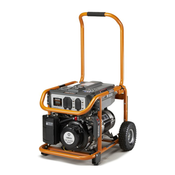
OPERATOR'S MANUAL
PORTABLE GENERATOR
NOTICE
Do not use E15 or E85 fuel (or
fuel containing greater than 10%
ethanol) in this product. It is a
violation of federal law and will damage the unit and
void your warranty.
Ne pas utiliser d'essence E15 ou E85 (ou un carburant
contenant plus de 10 % d'éthanol) dans ce produit. Une
telle utilisation représente une violation de la loi fédérale
et endommagera l'appareil et annulera la garantie.
No utilice combustibles E15 o E85 (ni combustibles que
contengan más de 10 % de etanol) con este producto.
Esto constituye una violación a la ley federal, dañará la
unidad y anulará la garantía.
NEUTRAL BONDED TO FRAME
(CONNECTEUR NEUTRE RELIÉ AU CADRE, PUNTO
NEUTRO CONECTADO AL MARCO)
Su generador portàtil diseñado y fabricado de conformidad con
nuestras estrictas normas para brindar fiabilidad, facilidad de uso
y seguridad para el operador. Con el debido cuidado, le brindará
muchos años de sólido funcionamiento y sin problemas.
ADVERTENCIA:
Para reducir el riesgo de lesiones, el usuario debe leer y
comprender el manual del operador antes de usar este
producto. Guarde este manual del operador y estúdielo
frecuentemente para lograr un funcionamiento seguro y
continuo de este producto.
GUARDE ESTE MANUAL PARA
FUTURAS CONSULTAS
Manuel de l'opérateur
Manual del operador
Générateur portable
Generador portàtil
RD903612
Series / Série / Serie
AVIS
AVISO
Advertisement
Table of Contents

Related Manuals for RIDGID RD903612 Series


Summary of Contents for RIDGID RD903612 Series
- Page 1 RIDGID, PORTABLE GENERATOR s’il vous plaît la visite: http://register.RIDGID.com Générateur portable Generador portàtil Para registrar su producto de RIDGID, por favor visita: RD903612 http://register.RIDGID.com Series / Série / Serie NOTICE AVIS AVISO Do not use E15 or E85 fuel (or fuel containing greater than 10% ethanol) in this product.
- Page 2 See this fold-out section for all of the figures referenced in the operator’s manual. Consulter l’encart à volets afin d’examiner toutes les figures mentionnées dans le manuel d’utilisation. Consulte esta sección desplegable para ver todas las figuras a las que se hace referencia en el manual del operador.
- Page 3 Fig. 1 Fig. 2 A - Reset button (bouton de réinitialisation, botón de reajuste) B - Test button (bouton de test, botón de prueba) A - Recoil starter grip (poignée du démarreur à G - Fuel tank (réservoir de carburant, tanque de L - AC circuit breaker [disjoncteur de C.A., rappel, mango del arrancador retráctil) combustible)
- Page 4 Fig. 3 1 - Axle bolt (boulon de l’essieu, perno de eje) 2 - Wheel (roue, rueda) 3 - Washer (rondelle, arandela) 4 - Hitch pin (goupille de sûreté, pasador del enganche) 5 - Lock nut (écrou de blocage, tuerca de seguridad) 6 - Leg with rubber foot (pied avec patin en caoutchouc, pata con pie de goma)
- Page 5 Fig. 10 Fig. 12 CIRCUIT BREAKER CIRCUIT BREAKER SMART DISPLAY A - SMART DISPLAY monitoring system C - 120 volt AC 20 amp receptacles [GFCI (système de surveillance SMART DISPLAY, protected] (prises 120 V C.A. 20 A [protégé sistema de monitoreo SMART DISPLAY) par un disjoncteur de fuite à...
- Page 6 Fig. 14 A - Fuel valve [on] (robinet de carburant [marche], válvula de combustible [encendido]) B - Fuel valve [off] (robinet de carburant [arret], válvula de combustible [ ]) C - Engine switch OFF (commutateur de moteur arret, interruptor del motor apagado) D - Engine switch ON (commutateur de moteur marche, interruptor del motor encendido)
- Page 7 Fig. 19 Fig. 20 Fig. 21 A - Fuel line (conduites de carburant, conducto de combustible) B - Fuel filter (filtre à carburant, filtro de A - Carburetor drain screw (vis de vidange combustible) du carburateur, tornillo de drenaje del carburador A - Fuel line (conduite de carburant, conducto de combustible)
-
Page 8: Table Of Contents
TABLE OF CONTENTS Introduction ..................................2 Important Safety Instructions ............................3-4 Specific Safety Rules ..............................4 Symbols ..................................5-7 Electrical ..................................7-9 Features ..................................10 Assembly ..................................11-12 Operation ..................................12-14 ... -
Page 9: Important Safety Instructions
IMPORTANT SAFETY INSTRUCTIONS Never start or run the engine inside a closed or partially DANGER: enclosed area. Breathing exhaust fumes will kill you. Carbon Monoxide. Using a generator indoors CAN Do not start or operate the engine in a confined space, KILL YOU IN MINUTES. -
Page 10: Specific Safety Rules
IMPORTANT SAFETY INSTRUCTIONS can become overloaded. This may result in overheating Maintain the unit per maintenance instructions in this or stressing the generator components, possibly leading Operator’s Manual. to generator failure. Inspect the unit before each use for loose fasteners, fuel Use only authorized replacement parts and accessories leaks, etc. -
Page 11: Symbols
SYMBOLS The following signal words and meanings are intended to explain the levels of risk associated with this product. SYMBOL SIGNAL MEANING Indicates an imminently hazardous situation, which, if not avoided, will result DANGER: in death or serious injury. Indicates a potentially hazardous situation, which, if not avoided, could result WARNING: in death or serious injury. - Page 12 SYMBOLS Some of the following symbols may be used on this product. Please study them and learn their meaning. Proper interpretation of these symbols will allow you to operate the product better and safer. SYMBOL NAME DESIGNATION/EXPLANATION Hertz Frequency (cycles per second) Watt Power Hours...
-
Page 13: Electrical
SYMBOLS FUEL WARNING No smoking when filling with gasoline. Do not overfill. Full level is 1 in. below the top of the fuel neck. Stop the engine for five minutes before refueling to avoid the heat from the muffler igniting fuel vapors. ENGINE LUBRICANT WARNING SPARK ARRESTOR You must add lubricant before first operating the generator. - Page 14 ELECTRICAL ELECTRIC MOTOR LOADS It is characteristic of common electric motors in normal operation to draw up to six times their running current while starting. This table may be used to estimate the watts required to start electric motors; however, if an electric motor fails to start or reach running speed, turn off the appliance or tool immediately to avoid equipment damage.
- Page 15 ELECTRICAL POWER MANAGEMENT Estimated* Estimated* To prolong the life of the generator and attached devices, Tool or Appliance Running Additional it is important to take care when adding electrical loads to Watts Starting Watts the generator. There should be nothing connected to the DIY/Job Site generator outlets before starting its engine.
-
Page 16: Features
FEATURES PRODUCT SPECIFICATIONS ENGINE Rated Running Watts* ..........3,600 W Engine Type ....Subaru, 4 Stroke, OHC (Chain Drive) Rated Starting Watts ..........4,500 W Fuel Volume ..............4 gal. Rated Frequency ............60 Hz DIMENSIONS Engine Lubricant Volume........... 20 oz. Length ..............29.5 in. GENERATOR Width ............... -
Page 17: Assembly
ASSEMBLY UNPACKING LOOSE PARTS LIST See Figure 3. This product requires assembly. The following items are included with the generator: Carefully cut the box down the sides then remove the machine and any accessories from the box. Make sure that all items listed in the loose parts list are included. -
Page 18: Operation
ASSEMBLY INSTALLING THE WHEELS Raise the handle end of the generator high enough to gain access to the frame bottom; securely position props See Figure 6. underneath to support. Wheels are provided to assist in moving the generator to the Insert the axle bolt through the center of the wheel. - Page 19 OPERATION RAISING AND LOWERING THE HANDLE Replace and secure the fuel tank cap. See Figure 7. Start and run the engine for at least 5 minutes to allow stabilizer to treat the entire fuel system. To raise the handle (for moving the generator): pull the handle up until the handle release knob snaps into locking OXYGENATED FUELS position.
-
Page 20: Maintenance
OPERATION used. Use this meter along with the accompanying engine NOTE: If location of generator is not level, the unit may not manual to determine when and what type of service on the start or may shut down during operation. unit is needed.
Need help?
Do you have a question about the RD903612 Series and is the answer not in the manual?
Questions and answers
What weight engine oil?